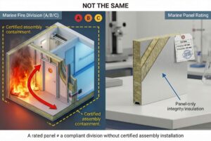
Selecting marine wall panels involves navigating complex regulations, technical specifications, and operational constraints that can make or break your interior decoration project. A wrong choice leads to certification failures, costly rework, and shipyard disputes.
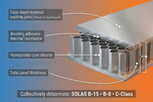
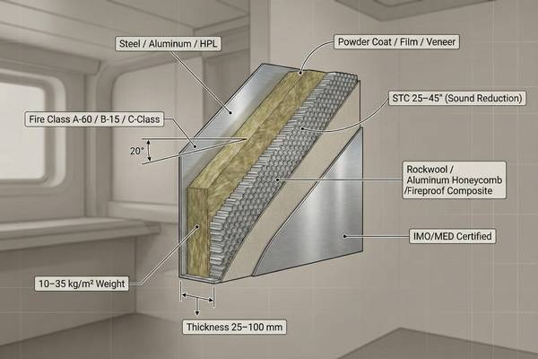
Marine wall panel selection hinges on eight critical parameters: fire class (A-60/A-30/A-15/A-0, B-15/B-0, or C-Class per SOLAS), thickness (25mm to 100mm based on structural needs), core material (rockwool, aluminum honeycomb, or fireproof board composites), sound reduction capability (STC ratings 25-45 depending on cabin type), facing material (steel, aluminum, or HPL laminates), surface finish (powder-coated, film-laminated, or veneer), weight (10-35 kg/m² affecting stability), and certification (IMO/MED compliance for regulatory acceptance). Each parameter directly impacts fire safety, acoustic comfort, installation logistics, and approval timelines across European and American shipyard standards.
This article breaks down each parameter systematically, providing specific selection criteria, industry-standard values, and technical justifications sourced from SOLAS regulations, ASTM testing standards, and shipyard procurement specifications. Understanding these parameters prevents procurement errors and ensures seamless project execution.
How to choose the right fire class for marine wall panels?
Fire class determines whether your panels meet mandatory safety zones on passenger vessels, cargo ships, and offshore platforms. Selecting an insufficient rating causes regulatory rejection during flag state inspections.
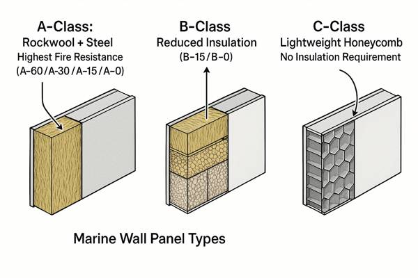
Marine wall panels are classified under SOLAS Chapter II-2 into three tiers: A-Class divisions (A-60, A-30, A-15, A-0) for high-risk bulkheads requiring rockwool cores and steel facings to withstand standard fire tests; B-Class divisions (B-15, B-0) for cabin partitions using rockwool or aluminum honeycomb cores with reduced insulation demands; and C-Class divisions for low-risk public spaces permitting lightweight aluminum honeycomb cores without fire insulation requirements. Selection depends on compartment fire risk, adjacent space functions, and flag state approval requirements.
SOLAS Fire Class Categories and Selection Criteria
SOLAS divides fire boundaries into distinct performance tiers based on temperature rise limits and structural integrity duration. A-Class divisions must prevent temperature rise beyond 140°C on the unexposed side for 60, 30, 15, or 0 minutes (A-60/A-30/A-15/A-0), measured per ISO 834 standard fire curve. These divisions always require incombustible materials—typically 0.6-1.0mm steel facings with 50-100mm rockwool cores (density 100-120 kg/m³ per ASTM E136).
B-Class divisions allow 140°C temperature rise within the first 30 minutes but must maintain integrity for 15 or 0 minutes (B-15/B-0). The critical distinction: B-Class permits combustible facings if protected by incombustible layers. Common configurations include 25-50mm rockwool cores or fireproof board + aluminum honeycomb hybrids, with 0.5mm steel or aluminum facings.
C-Class divisions represent non-fire-rated partitions for public corridors, lobbies, and administrative spaces where evacuation routes don't pass through. These panels use pure aluminum honeycomb cores (6-15mm cell size) with decorative HPL laminates or thin aluminum skins, prioritizing weight reduction over fire resistance.
Fire Class Selection by Compartment Type
| Compartment Type | Required Fire Class | Typical Configuration | Regulatory Basis |
|---|---|---|---|
| Engine room boundaries | A-60 | 100mm rockwool + 1.0mm steel | SOLAS Reg. II-2/9.2.2.3 |
| Main vertical zones | A-30 or A-60 | 75mm rockwool + 0.8mm steel | SOLAS Reg. II-2/9.2.1 |
| Cabin corridors (passenger ships) | B-15 | 30mm rockwool + 0.5mm steel | SOLAS Reg. II-2/9.2.2.4 |
| Stateroom partitions | B-0 | 25mm aluminum honeycomb + aluminum facing | SOLAS Reg. II-2/9.3.1 |
| Public lounges/restaurants | C-Class | 25mm aluminum honeycomb + HPL laminate | No fire rating required (open spaces) |
| Control stations | A-0 or A-15 | 50mm rockwool + 0.6mm steel | SOLAS Reg. II-2/9.2.4.1 |
Selection errors occur when procurement officers misinterpret "cabin walls" as uniformly B-Class. On cruise ships, cabins adjacent to stairwells require A-15 per escape route regulations (SOLAS Chapter II-2, Regulation 9.2.2.1). Always cross-reference compartment layout drawings with fire control plans before specifying classes.
Fire Testing Standards and Certification Evidence
Legitimate marine wall panels carry IMO Resolution A.754(18) approval certificates, demonstrating successful ISO 834 furnace testing at accredited laboratories (e.g., Warrington Fire, RINA, CCS). Request test reports showing:
- Temperature rise curves plotting unexposed surface temperature over 60+ minutes
- Insulation failure time marking when any point exceeds 180°C above ambient
- Integrity failure markers documenting crack formation, cotton pad ignition, or gap gauge penetration
Chinese manufacturers often provide CCS (China Classification Society) certificates under GB/T 9978 standard, equivalent to IMO requirements but requiring MED (Marine Equipment Directive) re-certification for EU-flagged vessels. Budget 8-12 weeks for MED notified body approval if original certificates lack EU recognition.
Fire Class Impact on Lead Time and Cost
A-Class panels cost 40-60% more than equivalent B-Class due to thicker rockwool (100mm vs. 30mm), heavier steel facings (1.0mm vs. 0.5mm), and additional fire barrier tapes at joints. Lead times extend 2-4 weeks as manufacturers await rockwool curing cycles (7-day compression set recovery per ASTM C167).
C-Class panels offer 50-70% weight savings (12 kg/m² vs. 28 kg/m²) and 30% cost reductions, but misapplication creates liability. One Indonesian contractor faced $45,000 in replacement costs after installing C-Class panels in crew corridors—flag state surveyors mandated B-15 upgrades during final inspection.
How to choose the right thickness for marine wall panels?
Thickness governs structural rigidity, acoustic isolation, and fire insulation capacity, directly affecting panel stability in rough seas and compliance with fire endurance tests.
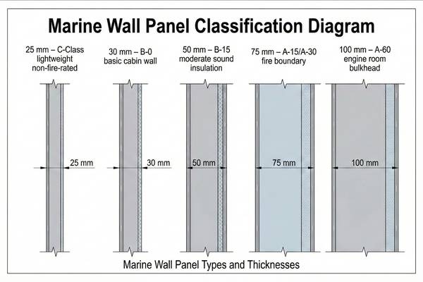
Marine wall panels are manufactured in five standard thicknesses: 25mm for lightweight non-fire-rated partitions (C-Class public spaces), 30mm for basic B-0 cabin walls, 50mm for B-15 divisions requiring moderate sound insulation, 75mm for A-15/A-30 fire boundaries in accommodation areas, and 100mm for A-60 engine room bulkheads demanding maximum thermal resistance. Thickness selection balances SOLAS fire rating requirements (core insulation depth), structural deflection limits (L/360 per shipyard specs), and weight budgets (critical for upper deck stability calculations per IMO Intact Stability Code).
Thickness Requirements by Fire Class
Fire class directly dictates minimum core thickness because insulation performance depends on material depth. SOLAS IMO Resolution A.754(18) implicitly mandates specific insulation layers through temperature rise limits, translated into practical thickness standards by classification societies.
A-60 Divisions: Require 100mm minimum core thickness using 100-120 kg/m³ density rockwool to achieve 60-minute temperature rise containment. Testing per ISO 834 shows 75mm cores fail at 48-52 minutes as heat flux overwhelms insulation capacity. The additional 25mm provides safety margin for manufacturing tolerances and aging degradation.
A-30/A-15 Divisions: Utilize 75mm cores (A-30) or 50mm cores (A-15) with identical rockwool density. Thinner panels compensate through enhanced facings—A-15 panels often use 0.8mm steel instead of 0.6mm to delay structural failure.
B-Class Divisions: Allow flexibility due to lower insulation demands. B-15 panels typically use 30-50mm cores (rockwool or fireproof board + aluminum honeycomb hybrids), while B-0 accepts 25mm pure aluminum honeycomb or thin rockwool layers.
C-Class Divisions: Require only 6mm minimum thickness per SOLAS definition of "constructed of approved non-combustible materials," though practical panels use 25mm aluminum honeycomb for rigidity.
Thickness Selection Based on Structural Deflection Limits
Shipyards impose deflection limits (typically L/360 where L = panel span) to prevent visible bowing, cracked joints, and door jamming during 30-degree roll angles. Thickness directly affects panel moment of inertia, governing deflection under lateral pressure.
| Panel Span (Height) | Minimum Thickness for L/360 Deflection | Core Material | Facing Gauge | Deflection at 100 Pa Lateral Load |
|---|---|---|---|---|
| 2400mm (8 ft) | 25mm | Aluminum honeycomb | 0.5mm aluminum | 6.2mm (acceptable) |
| 2700mm (9 ft) | 30mm | Aluminum honeycomb | 0.5mm aluminum | 6.8mm (acceptable) |
| 3000mm (10 ft) | 50mm | Rockwool + honeycomb | 0.6mm steel | 7.5mm (acceptable) |
| 3000mm (10 ft) | 30mm | Pure aluminum honeycomb | 0.5mm aluminum | 11.2mm (fails L/360) |
These values derive from beam deflection formulas (δ = 5wL⁴/384EI) using composite panel properties. When span exceeds 2700mm, 25mm panels require mid-height horizontal stiffeners—adding installation complexity and joint leakage risks.
Thickness Impact on Weight and Stability
Upper deck accommodations face strict weight limits per IMO Intact Stability Code (2008), where excessive superstructure weight raises the center of gravity (KG), reducing metacentric height (GM) and stability. Each 10mm thickness increase adds 3-5 kg/m² depending on core density.
For a typical 80-cabin cruise ship module (2,000 m² wall area):
- 25mm C-Class panels: 24,000 kg total (12 kg/m²)
- 50mm B-15 panels: 48,000 kg total (24 kg/m²)
- 100mm A-60 panels: 70,000 kg total (35 kg/m²)
The 46,000 kg difference between C-Class and A-60 specifications shifts KG by approximately 0.15-0.20 meters on a 15,000 GT vessel, potentially requiring ballast adjustments or hull redesigns.
Acoustic Considerations in Thickness Selection
Thickness indirectly affects sound insulation through core material depth and facing mass. While dedicated acoustic sections address this further, thickness selection must anticipate sound transmission class (STC)1 requirements:
- 25mm C-Class panels: STC 25-28 (insufficient for sleeping cabins)
- 30mm B-0 panels: STC 30-33 (minimum for passenger staterooms)
- 50mm B-15 panels: STC 35-40 (standard for officer cabins)
- 75mm A-15 panels: STC 40-45 (luxury suite partitions)
Shipyards often default to 50mm thickness for accommodation blocks, balancing B-15 fire rating, STC 35+ acoustics, and manageable weight—a pragmatic compromise avoiding over-specification.
Thickness Selection for Door/Window Jamb Integration
Panel thickness must align with marine door frame depths (typically 50mm, 75mm, 100mm per ISO 5774 standard2) to ensure flush mounting and proper gasket compression. Mismatched thicknesses require custom adapter frames, adding $80-150 per opening.
C-Class 25mm panels mating with standard 50mm door frames create 25mm gaps requiring infill plates, compromise fire ratings at penetrations, and complicate certification. Always confirm door supplier specifications before finalizing panel thickness.
How to choose the right core material for marine wall panels?
Core material determines fire resistance duration, weight efficiency, acoustic damping, and long-term dimensional stability under marine humidity and vibration.
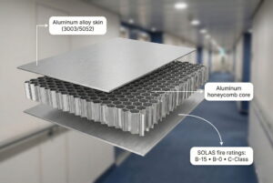
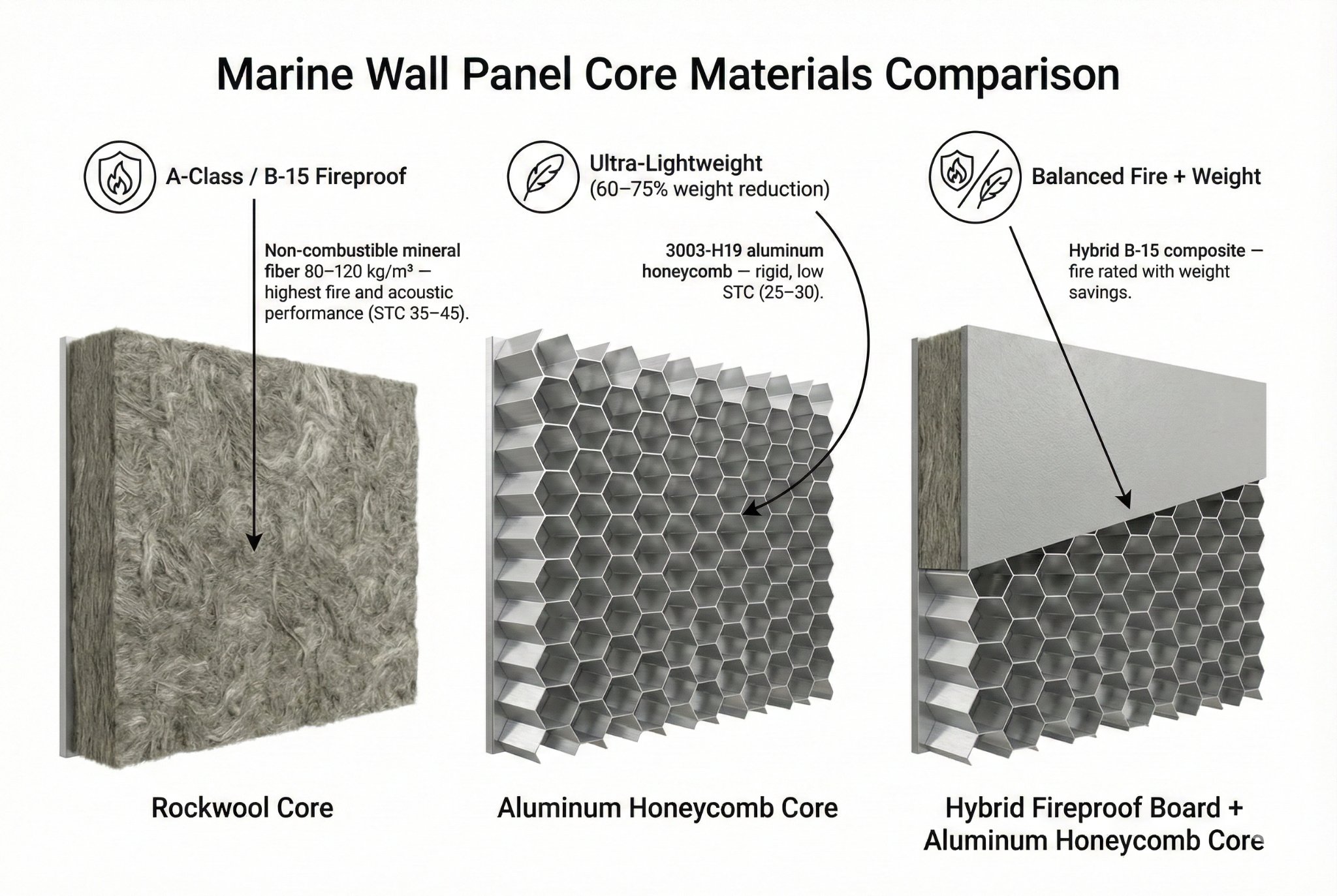
Marine wall panel cores consist of three primary materials: rockwool (mineral fiber density 80-120 kg/m³) for A-Class and B-15 fire divisions providing superior thermal insulation and sound absorption; aluminum honeycomb (3003-H19 alloy, 6-20mm cell size) for B-0 and C-Class panels offering 60-75% weight reduction while maintaining rigidity; and hybrid fireproof board + aluminum honeycomb composites for B-15 applications balancing fire performance with weight savings. Selection depends on fire class mandates (SOLAS dictates incombustible cores for A-Class), acoustic targets (rockwool achieves STC 35-45 vs. honeycomb's STC 25-30), and stability requirements (rockwool resists 95% relative humidity without degradation per ASTM C1104).
Core Material Requirements by Fire Class
SOLAS Chapter II-2 implicitly mandates core materials through incombustibility definitions and temperature rise limits, translated into specific materials by classification societies and testing labs.
A-Class Fire Divisions (A-60/A-30/A-15/A-0): Exclusively use rockwool (also called mineral wool or stone wool) meeting ASTM E1363 incombustibility criteria. Rockwool consists of basalt rock melted at 1500°C and spun into fibers, creating a matrix trapping air pockets. Density requirements:
- A-60 cores: 100-120 kg/m³ (100mm thickness)
- A-30 cores: 100-110 kg/m³ (75mm thickness)
- A-15 cores: 90-100 kg/m³ (50mm thickness)
Lower densities fail ISO 834 tests as fibers compress under heat, reducing insulation thickness and accelerating temperature rise. Higher densities add unnecessary weight without performance gains.
B-15 Fire Divisions: Permit two configurations:
- Rockwool cores: 80-100 kg/m³ density, 30-50mm thickness, providing STC 35-40 acoustics alongside fire resistance
- Fireproof board + aluminum honeycomb hybrids: 12mm calcium silicate board4 (density 850 kg/m³, tested per ASTM E136) bonded to 20-38mm aluminum honeycomb (6-12mm cells), achieving B-15 rating while reducing weight by 35% compared to pure rockwool
B-0 Fire Divisions: Allow three options:
- Thin rockwool cores: 80 kg/m³ density, 25-30mm thickness
- Pure aluminum honeycomb: 3003-H19 alloy, 10-15mm cell size, 25-50mm thickness, meeting "non-combustible" definition but lacking insulation
- Fireproof board sandwich: Two 6mm calcium silicate boards enclosing 13mm honeycomb
C-Class Non-Fire-Rated Divisions: Exclusively use pure aluminum honeycomb cores (6-20mm cell size) prioritizing weight and cost efficiency. Minimum 6mm total thickness per SOLAS non-combustible material definition, though 25mm practical minimum ensures rigidity.
Rockwool Core Material Properties and Selection
Rockwool dominates fire-rated marine panels due to unique thermal properties. Melting point exceeds 1000°C (vs. aluminum's 660°C), fibers maintain structure during fires, and trapped air pockets resist convective heat transfer.
| Rockwool Grade | Density (kg/m³) | Thermal Conductivity (W/m·K at 10°C) | Compression Strength (kPa at 10% deformation) | Application |
|---|---|---|---|---|
| Standard Marine Grade | 80-90 | 0.036-0.038 | 30-35 | B-0/B-15 cabin partitions |
| High-Density Fire Grade | 100-110 | 0.034-0.036 | 40-50 | A-15/A-30 accommodation bulkheads |
| Premium A-60 Grade | 110-120 | 0.033-0.035 | 50-60 | Engine room boundaries, main vertical zones |
Thermal conductivity inversely correlates with insulation performance—lower values indicate better heat blockage. The 0.003 W/m·K difference between 80 kg/m³ and 120 kg/m³ grades translates to 8-12 minutes additional fire resistance in ISO 834 testing.
Compression strength matters during installation and long-term service. Panels subjected to impact (galley walls, machinery spaces) require 40+ kPa grades to prevent permanent denting. Lower-grade rockwool in high-traffic corridors shows visible indentations after 2-3 years as crew members lean against walls.
Water repellency separates marine-grade from building-grade rockwool. Marine specifications demand hydrophobic treatment (silicone or oil-based coatings) achieving <1% water absorption per ASTM C1104 immersion testing. Untreated rockwool absorbs 5-8% moisture in marine environments, increasing weight, degrading R-value, and promoting corrosion of steel facings.
Aluminum Honeycomb Core Material Properties and Selection
Aluminum honeycomb offers structural efficiency through geometric optimization. Hexagonal cells resist compression perpendicular to facings while weighing 3-8 kg/m³—a 95% weight reduction versus solid aluminum.
Cell Size Selection Criteria:
- 6mm cells: Maximum strength (compression 2.5-3.0 MPa), used in door panels and high-impact zones, core density 80-100 kg/m³
- 10mm cells: Balanced strength/weight (compression 1.5-2.0 MPa), standard for B-0/C-Class walls, core density 50-70 kg/m³
- 15mm cells: Lightweight (compression 0.8-1.2 MPa), suitable for ceiling panels and curved surfaces, core density 30-45 kg/m³
- 20mm cells: Ultra-light (compression 0.5-0.8 MPa), specialty applications like removable access panels, core density 25-35 kg/m³
Cell size inversely affects both strength and cost. 6mm honeycomb costs $28-35/m² versus $18-24/m² for 15mm cells due to increased aluminum foil consumption and slicing precision requirements.
Alloy Specification: Marine honeycomb exclusively uses 3003-H19 aluminum alloy (98% aluminum, 1.2% manganese) for corrosion resistance in salt spray environments. Inferior 1100 alloy (99.5% pure aluminum) corrodes within 18-24 months in engine room applications, creating white powder deposits and structural weakening.
Foil thickness ranges from 0.03mm (lightweight C-Class panels) to 0.06mm (high-strength door cores). Thicker foils double compression strength5 but add 40% weight—a critical trade-off for upper deck installations.
Fireproof Board + Honeycomb Hybrid Cores
This composite solution emerged to achieve B-15 fire ratings while maintaining honeycomb's weight advantages. Configuration consists of:
Layer 1: 0.5mm steel or aluminum facing
Layer 2: 6-12mm calcium silicate fireproof board (density 850-1000 kg/m³, incombustible per ASTM E136)
Layer 3: 20-38mm aluminum honeycomb (10-15mm cells)
Layer 4: 6-12mm calcium silicate fireproof board (mirror of Layer 2)
Layer 5: 0.5mm steel or aluminum facing
Total thickness: 35-50mm, weight: 18-24 kg/m² (versus 24-30 kg/m² for equivalent rockwool B-15 panels).
The fireproof board provides thermal resistance while honeycomb maintains structural rigidity. ISO 834 testing shows this hybrid achieves 15-minute integrity and insulation at 35% lighter weight than pure rockwool—a significant advantage for retrofits on weight-limited vessels.
Limitations: Fireproof boards exhibit brittleness compared to rockwool's flexibility. Panels subjected to frequent vibration (near engine mounts, propeller shafts) develop micro-cracks after 3-5 years, potentially compromising fire ratings. CCS and RINA approve this core for accommodation areas but often reject it for machinery space boundaries.
Core Material Selection by Acoustic Requirements
Sound transmission class (STC) varies dramatically across core materials due to differing damping mechanisms:
| Core Material | Thickness | Typical STC Rating | Sound Absorption Coefficient (NRC) | Acoustic Mechanism |
|---|---|---|---|---|
| Rockwool 80 kg/m³ | 30mm | 30-33 | 0.75-0.85 | Fiber friction dissipates sound energy |
| Rockwool 100 kg/m³ | 50mm | 35-40 | 0.80-0.90 | Enhanced fiber density increases absorption |
| Rockwool 120 kg/m³ | 75mm | 40-45 | 0.85-0.95 | Maximum absorption across 500-4000 Hz |
| Aluminum honeycomb | 25mm | 25-28 | 0.10-0.20 | Minimal damping, sound reflects/transmits |
| Fireproof board + honeycomb | 40mm | 30-35 | 0.40-0.55 | Board provides moderate absorption |
Rockwool's fibrous structure traps sound waves through viscous friction—air molecules oscillating between fibers convert acoustic energy to heat. Aluminum honeycomb lacks this mechanism; sound waves reflect off cell walls with minimal energy loss.
For passenger cabins, shipyards typically mandate STC 35 minimum per IMO Resolution A.468(XII) noise standards. This effectively eliminates pure honeycomb options, limiting B-0 cabin walls to rockwool or hybrid cores despite weight penalties.
Officer cabins and VIP suites often require STC 40+, necessitating 50-75mm rockwool cores regardless of fire class. The acoustic requirement drives thickness selection rather than fire rating in these applications.
Core Material Dimensional Stability and Durability
Marine environments impose 40-95% relative humidity, 5-50°C temperature swings, and constant vibration at 8-25 Hz frequencies (propeller/engine harmonics). Core materials must resist degradation under these conditions throughout 25-30 year vessel lifespans.
Rockwool Stability: Marine-grade rockwool with hydrophobic treatment shows <0.5% dimensional change after 10,000 hours at 90% RH per ASTM C1104. Fiber structure remains intact, maintaining both fire and acoustic properties. However, impact resistance degrades—panels in high-traffic areas show 8-12mm permanent indentations after 5 years as fiber compression accumulates.
Aluminum Honeycomb Stability: 3003-H19 alloy resists corrosion in salt spray (ASTM B117) for 5,000+ hours without structural degradation. Dimensional stability exceeds rockwool—honeycomb geometry prevents creep. However, galvanic corrosion occurs at steel-aluminum interfaces without proper insulation (zinc-rich primers or polyethylene barriers), causing 15-20% strength loss over 10 years.
Fireproof Board Stability: Calcium silicate boards absorb 8-12% moisture at 90% RH, causing 1.5-2.0mm thickness expansion and 0.3% linear growth. This creates visible panel buckling in humidity-cycled spaces (laundries, galleys). Long-term vibration induces micro-cracking, potentially compromising fire ratings after 7-10 years. Classification societies require re-testing of fireproof board panels at 10-year intervals—a maintenance burden absent for rockwool cores.
Core Material Cost Analysis and Lead Time Impact
Core material constitutes 35-45% of total panel cost, making selection financially significant on large projects.
Cost per m² (50mm thickness basis):
- Rockwool 100 kg/m³: $12-16/m²
- Aluminum honeycomb 10mm cells: $22-28/m²
- Fireproof board + honeycomb hybrid: $18-24/m²
The honeycomb premium stems from aluminum commodity pricing and precision manufacturing. However, weight savings reduce shipping costs—a 20-foot container holds 850 m² of honeycomb panels versus 620 m² of rockwool panels, reducing freight by 27% on Indonesia-to-Europe shipments.
Lead times vary: rockwool panels ship in 4-6 weeks, aluminum honeycomb requires 6-8 weeks (honeycomb slicing and adhesive curing), and fireproof board hybrids need 7-9 weeks (multi-stage lamination and fire testing).
How to choose the right sound reduction capability for marine wall panels?
Sound reduction capability determines passenger comfort, regulatory compliance with IMO noise codes, and crew productivity in accommodation spaces through control of airborne noise transmission.
Marine wall panel sound reduction is measured using Sound Transmission Class (STC) ratings ranging from STC 25 (minimal isolation, suitable for public corridors and storage areas) to STC 45 (superior isolation for luxury suites and control rooms). SOLAS and IMO Resolution A.468(XII) mandate minimum STC 30 for passenger cabins, STC 35 for crew accommodations adjacent to machinery spaces, and STC 40 for hospital/radio rooms. Selection depends on compartment function (sleeping vs. public spaces), adjacent noise sources (engine rooms generate 95-110 dBA requiring higher isolation), panel construction (core material density, facing mass, and air cavity depth per mass law principles), and certification requirements (testing per ISO 140-3 or ASTM E90 standards at accredited acoustic laboratories).

IMO and SOLAS Acoustic Requirements by Compartment Type
IMO Resolution A.468(XII) "Code on Noise Levels on Board Ships" establishes mandatory sound pressure limits for crew and passenger spaces, indirectly dictating partition STC requirements. These limits protect hearing, enable sleep, and ensure intelligibility in safety-critical areas.
Passenger Cabin Requirements:
- Maximum sound pressure level: 60 dBA during normal operations
- Minimum partition STC: 30 (separating cabins from corridors)
- Enhanced STC: 35-40 (separating cabins from dining/entertainment venues)
Achieving 60 dBA interior levels when corridor traffic generates 70-75 dBA requires STC 30 partitions. However, cabins adjacent to nightclubs (85-95 dBA) or casinos need STC 40-45 to meet the 60 dBA interior target—a 10-point STC increase per 10 dBA exterior source elevation.
Crew Accommodation Requirements:
- Maximum sound pressure level: 60 dBA (cabins), 65 dBA (mess rooms), 75 dBA (machinery control rooms)
- Minimum partition STC: 30 (cabin-to-cabin), 35 (cabin-to-corridor near engines), 40 (cabin-to-engine casing)
Crew quarters near main engines face 95-110 dBA exterior noise. Achieving 60 dBA interiors demands STC 40-50 partitions, often requiring double-wall constructions with resilient channels—exceeding standard panel capabilities.
Specialized Space Requirements:
| Compartment Type | Max Interior dBA (IMO A.468) | Typical Adjacent Noise | Required Partition STC | Acoustic Justification |
|---|---|---|---|---|
| Hospital/medical rooms | 50-55 dBA | Corridor 70 dBA | STC 35-40 | Patient rest, examination privacy |
| Radio/communication rooms | 60 dBA | Deck machinery 85 dBA | STC 40-45 | Signal clarity, operator concentration |
| Officer cabins | 55 dBA | Corridor 68 dBA | STC 35-38 | Elevated rest standards |
| Passenger luxury suites | 50 dBA | Public spaces 75 dBA | STC 40-45 | Premium comfort expectations |
| Crew mess halls | 65 dBA | Galley 80 dBA | STC 30-35 | Speech intelligibility |
| Engine control rooms | 75 dBA | Engine room 110 dBA | STC 45-50 | Operator safety, alarm audibility |
These STC targets derive from the fundamental acoustic equation: STC_required ≈ Exterior_dBA - Interior_dBA_target + 10 (the +10 accounts for sound flanking through structure and ventilation).
Panel Construction Parameters Affecting STC Ratings
Sound transmission class depends on three physical mechanisms governed by mass law, resonance damping, and absorption principles established in acoustic engineering.
Facing Mass Effect: Heavier facings increase STC per mass law (TL ≈ 20log(M·f) - 47, where TL = transmission loss, M = surface mass kg/m², f = frequency Hz). Doubling facing mass adds approximately 6 dB transmission loss.
Practical marine panel facings:
- 0.5mm steel facings: 7.8 kg/m² surface mass → STC 28-32 (with 25mm rockwool core)
- 0.8mm steel facings: 12.5 kg/m² surface mass → STC 33-37 (with 25mm rockwool core)
- 1.0mm steel facings: 15.6 kg/m² surface mass → STC 36-40 (with 50mm rockwool core)
The 5-8 point STC improvement from 0.5mm to 1.0mm facings comes at 100% weight increase—a trade-off requiring stability analysis.
Core Material Damping: Rockwool's fibrous structure dissipates sound energy through viscous friction, adding 8-12 STC points versus equivalent hollow aluminum honeycomb panels. Higher-density rockwool enhances absorption:
- 80 kg/m³ rockwool, 30mm: STC 30-33
- 100 kg/m³ rockwool, 50mm: STC 35-40
- 120 kg/m³ rockwool, 75mm: STC 40-45
Aluminum honeycomb provides minimal damping (STC 25-28 for equivalent thickness) as sound waves reflect off cell walls without energy dissipation. Hybrid fireproof board + honeycomb cores achieve intermediate performance (STC 30-35) through board's moderate absorption.
Air Cavity Resonance: Double-panel constructions with air gaps exhibit resonance frequencies (f_resonance = 60/√(d·M), where d = cavity depth cm, M = panel mass kg/m²) causing STC dips. Marine panels avoid this through solid core construction, maintaining consistent transmission loss across 125-4000 Hz frequency range.
STC Testing Standards and Certification Requirements
Classification societies require ISO 140-3 or ASTM E90 laboratory testing to validate STC claims. Testing involves:
- Sample preparation: 3m × 2.4m panel section mounted in transmission loss suite
- Source room excitation: Pink noise generator producing 100 dB SPL at 125-4000 Hz (1/3 octave bands)
- Receiving room measurement: Sound pressure levels recorded via calibrated microphones
- Transmission loss calculation: TL = SPL_source - SPL_receiving + 10log(A/S), where A = receiving room absorption, S = panel area
- STC computation: Transmission loss values fitted to ASTM E413 reference curve, deficiency analysis determines STC rating
Accredited laboratories (Warrington Fire, RINA, CCS, TNO) issue certificates valid for 5 years, requiring re-testing if panel construction changes. Certificates must document:
- Test sample construction details (facing gauge, core type/density, thickness)
- 1/3 octave transmission loss data (125 Hz to 4000 Hz)
- STC rating with 95% confidence interval (e.g., STC 35 ± 2)
Chinese manufacturers often provide CCS testing per GB/T 19889 standard, acoustically equivalent to ISO 140-3 but requiring MED re-certification for EU vessels. Budget $3,500-6,000 for STC re-testing at EU notified bodies if original certificates lack recognition.
Acoustic Performance vs. Weight Trade-offs
Achieving high STC ratings conflicts with weight minimization goals, creating engineering compromises on upper deck accommodations.
| Target STC | Minimum Configuration | Panel Weight (kg/m²) | Fire Class | Typical Application |
|---|---|---|---|---|
| STC 25-28 | 25mm aluminum honeycomb + 0.5mm aluminum facings | 10-12 | C-Class | Public corridors, storage |
| STC 30-33 | 30mm rockwool 80 kg/m³ + 0.5mm steel facings | 18-22 | B-0 or B-15 | Standard passenger cabins |
| STC 35-38 | 50mm rockwool 100 kg/m³ + 0.6mm steel facings | 24-28 | B-15 or A-15 | Officer cabins, crew quarters |
| STC 40-43 | 75mm rockwool 110 kg/m³ + 0.8mm steel facings | 30-35 | A-15 or A-30 | Luxury suites, hospital rooms |
| STC 45+ | 100mm rockwool 120 kg/m³ + 1.0mm steel facings | 38-45 | A-60 | Radio rooms, engine control stations |
Each 5-point STC increase adds approximately 6-10 kg/m² through thicker cores and heavier facings. On a 150-cabin cruise ship module (3,000 m² partition area), upgrading from STC 30 to STC 40 adds 18,000-30,000 kg—equivalent to 180-300 passengers' weight, significantly impacting stability calculations.
Naval architects often specify STC 35 as the optimal balance point: exceeds IMO minimums by 5 points (providing acoustic safety margin), achieves B-15 fire rating, and maintains reasonable weight (24-28 kg/m²). Deviations require explicit justification through noise surveys or passenger complaint data.
Field Acoustic Performance vs. Laboratory STC Ratings
Laboratory STC values represent idealized performance under perfect sealing conditions. Field installations suffer 5-12 point degradations due to sound flanking paths that bypass partitions.
Primary Flanking Mechanisms:
- Structural transmission: Sound energy travels through steel deck/overhead connections, bypassing panels (5-8 dB flanking loss)
- Perimeter gaps: Improper sealant application at panel-to-structure joints creates 1-3mm gaps (8-15 dB degradation)
- Penetration leaks: Electrical conduits, HVAC ducts, and pipe penetrations without acoustic sealing (10-20 dB degradation per unsealed opening)
- Door undercuts: Standard 10-15mm door clearances transmit sound (reduces effective wall STC by 3-6 points)
Achieving field STC within 3 points of laboratory ratings requires:
- Resilient gaskets at all panel-to-structure interfaces (closed-cell EPDM, 10mm compression)
- Acoustic sealant at vertical/horizontal joints (polyurethane or silicone, 6mm bead)
- Fire-rated acoustic putty pads around all penetrations (UL listed, 3mm thickness)
- Perimeter sealing at door frames (adjustable drop seals, threshold sweeps reducing undercut to <6mm)
Installation specifications must mandate these details. One contractor achieved only STC 26 field performance from STC 35 panels due to omitted perimeter sealant—resulting in passenger complaints and $180,000 retrofit costs.
Acoustic Performance Verification and Acceptance Testing
High-value projects (cruise ships, offshore accommodation modules) increasingly require field acoustic testing to verify installed performance before final acceptance.
Field Testing Protocol (per ISO 16283-1):
- Equipment: Dodecahedron speaker, Class 1 sound level meters, pink noise generator
- Test positions: Minimum 3 source room positions, 5 receiving room positions
- Measurement: SPL recorded in 1/3 octave bands (100-5000 Hz), background noise correction applied
- Analysis: Field STC computed per ASTM E413, compared against specification
Acceptance criteria typically allow 3-point tolerance: specified STC 35 panels must achieve field STC 32 minimum. Failures trigger remediation (additional sealant, penetration sealing, resilient channel installation) until compliance achieved.
Testing costs $800-1,500 per cabin pair, making statistical sampling necessary on large projects. Industry practice tests 5-10% of cabins randomly selected across ship sections, with 95% passing rate required for acceptance.
How to choose the right facing material for marine wall panels?
Facing material determines surface durability, corrosion resistance, aesthetic versatility, and compatibility with fire rating requirements through selection of incombustible or protected combustible sheets.
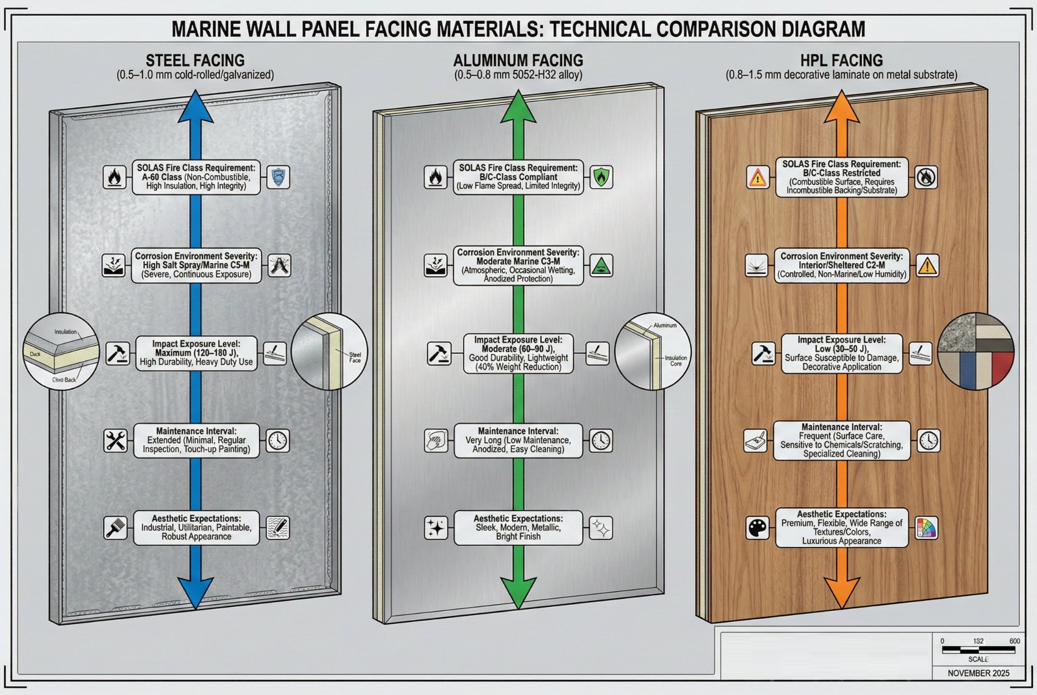
Marine wall panel facings consist of three primary materials: steel facings (0.5-1.0mm cold-rolled or galvanized, mandatory for A-Class divisions per SOLAS incombustibility requirements, providing superior impact resistance 120-180 J and corrosion protection when properly primed); aluminum facings (0.5-0.8mm 5052-H32 alloy, permitted for B-Class and C-Class panels, offering 40% weight savings versus steel but reduced impact resistance 60-90 J); and high-pressure laminate (HPL) facings (0.8-1.5mm decorative laminates bonded to steel/aluminum substrates, allowed on B-Class/C-Class panels when protected by incombustible backing, providing unlimited aesthetic options but requiring careful fire testing to verify compliance). Selection balances SOLAS incombustibility mandates, corrosion environment severity (salt spray in weather decks vs. controlled interior atmospheres), impact exposure (galley/machinery vs. staterooms), maintenance requirements (steel repainting every 5-7 years vs. aluminum anodizing lasting 15-20 years), and finish expectations (functional vs. luxury hospitality aesthetics).
Facing Material Requirements by Fire Class
SOLAS Chapter II-2 and IMO Resolution A.753(18) define "incombustible material" as substances showing no flame, weight loss <50%, or temperature rise >750°C when tested per ISO 1182. This definition strictly limits facing options for fire-rated divisions.
A-Class Division Facings: Must use incombustible materials exclusively, restricting choices to:
- Cold-rolled steel6: 0.6-1.0mm SPCC or equivalent, pickled and oiled surface
- Galvanized steel7: 0.6-1.0mm G60-G90 coating (60-90 g/m² zinc per side)
- Stainless steel: 0.5-0.8mm 304/316 grade (premium applications, hospital/galley areas)
Aluminum qualifies as incombustible (melting point 660°C exceeds ISO 1182 criteria) but rarely appears on A-Class panels due to lower melting point versus steel (1538°C), creating earlier structural failure concerns during extended fire exposure. Classification societies approve aluminum A-Class facings only with engineering substantiation through full-scale ISO 834 testing.
B-Class Division Facings: Permit incombustible materials plus combustible facings protected by incombustible layers:
- Bare steel/aluminum: 0.5-0.8mm gauge (standard approach)
- HPL laminate on steel substrate: 0.8-1.2mm HPL bonded to 0.5mm steel (decorative finish)
- Powder-coated aluminum: 0.5-0.6mm aluminum with 60-100 micron polyester coating (color options)
The critical requirement: combustible layers (HPL, powder coating) must remain protected by underlying incombustible substrate during fire testing. Test reports must document that flame/heat exposure does not directly contact combustible surface until after integrity failure.
C-Class Division Facings: No fire restrictions, allowing any architectural material:
- Thin aluminum: 0.4-0.6mm (weight optimization)
- Thick HPL: 1.2-1.8mm decorative laminates (direct-applied without metal backing)
- Composite panels: Aluminum-plastic composite sheets, wood veneers on aluminum (luxury aesthetics)
However, SOLAS still requires overall "non-combustible" construction, excluding pure plastic or wood panels. Classification societies interpret this as requiring incombustible core (aluminum honeycomb) even if facings contain combustible elements.
Steel Facing Properties and Selection Criteria
Steel facings dominate fire-rated marine panels (A-Class and B-15) due to proven performance, cost-effectiveness, and surface treatment versatility.
Cold-Rolled Steel (SPCC Grade):
- Composition: Low-carbon steel (0.08-0.12% carbon), cold-worked for dimensional accuracy
- Surface finish: Pickled and oiled (removes scale, prevents flash rust)
- Gauge range: 0.5-1.0mm (0.5mm for B-Class, 0.8-1.0mm for A-60)
- Tensile strength: 270-350 MPa (adequate for panel rigidity)
- Cost: $0.65-0.85/kg FOB China
Cold-rolled steel requires immediate priming after fabrication (within 48 hours) to prevent corrosion. Bare steel exposed to marine atmospheres develops visible rust in 7-14 days, compromising both aesthetics and facing-to-core adhesion. Manufacturers typically apply zinc-rich epoxy primer (60-80 micron DFT) immediately post-fabrication.
Galvanized Steel (G60-G90 Grade):
- Composition: Cold-rolled steel with hot-dip zinc coating
- Coating weight: G60 (60 g/m² per side = 8.5 micron), G90 (90 g/m² = 12.7 micron)
- Corrosion resistance8: 500-1000 hours salt spray (ASTM B117) before red rust
- Cost premium: +15-25% versus bare cold-rolled steel
Galvanized facings eliminate immediate priming requirements, extending fabrication-to-installation windows from 2 weeks to 3-4 months without corrosion risk. However, zinc coating complicates subsequent painting—requires specialized zinc-compatible primers and reduces topcoat adhesion versus bare steel.
Panel specifications for weather-exposed areas (external accommodation blocks, helicopter hangars) should mandate G90 galvanized facings. Interior cabin areas accept G60 or bare steel with proper priming systems.
Stainless Steel Facings (304/316 Grade):
- Composition: 18% chromium, 8-10% nickel (304), +2% molybdenum (316 for enhanced chloride resistance)
- Corrosion resistance: Excellent in marine environments, minimal maintenance
- Cost: $2,400-3,200/tonne (3.5-4.5× cold-rolled steel)
- Applications: Hospital rooms (hygiene), galley walls (food safety), pharmaceutical storage
Stainless steel facings eliminate painting requirements, reducing lifecycle costs despite 300%+ initial premiums. However, stainless panels require careful specification: 304 grade suffers pitting corrosion in salt spray, mandating 316 grade for weather-exposed applications.
Aluminum Facing Properties and Selection Criteria
Aluminum facings appear on B-Class and C-Class panels where weight reduction justifies performance compromises versus steel.
5052-H32 Alloy9 (Standard Marine Grade):
- Composition: 2.5% magnesium, 0.25% chromium (corrosion resistance)
- Temper: H32 (strain-hardened + stabilized, balancing formability and strength)
- Gauge range: 0.5-0.8mm (0.5mm for C-Class, 0.7-0.8mm for B-Class)
- Tensile strength: 195-250 MPa (28% lower than equivalent steel)
- Weight: 2.7 kg/m² per mm thickness (65% lighter than steel's 7.85 kg/m²)
- Cost: $2.40-2.80/kg FOB China
The 40% weight savings (0.5mm aluminum = 1.35 kg/m² vs. 0.5mm steel = 3.92 kg/m²) significantly benefits upper deck installations. However, lower tensile strength requires thicker gauges for equivalent rigidity: 0.5mm steel rigidity ≈ 0.7mm aluminum, partially negating weight advantage.
Aluminum Corrosion Mechanisms: Unlike steel's uniform rusting, aluminum forms protective aluminum oxide layers preventing further degradation. However, galvanic corrosion occurs when aluminum contacts dissimilar metals (steel framing, fasteners) in salt water:
- Aluminum (anode, -1.66V vs. SCE) corrodes preferentially
- Steel (cathode, -0.61V) remains protected
- Corrosion rate: 20-60 microns/year at contact points without insulation
Proper detailing requires nylon washers, bituminous tapes, or zinc-rich primers at all aluminum-steel interfaces. One project experienced complete aluminum facing degradation within 36 months due to uninsulated steel studs—resulting in $320,000 replacement costs.
Anodized Aluminum Finishes:
- Process: Electrochemical oxidation creating 10-25 micron aluminum oxide layer
- Color options: Natural silver, bronze, black (dye absorption during anodizing)
- Durability: Oxide layer increases corrosion resistance 5-10×, eliminates painting
- Cost premium: +$0.40-0.70/m² versus bare aluminum
Anodized finishes provide 15-20 year maintenance-free service versus 5-7 year repaint cycles for coated steel, justifying premiums on high-visibility public spaces (lobbies, dining rooms, atriums).
High-Pressure Laminate (HPL)10 Facing Properties
HPL facings enable decorative finishes (wood grains, stone patterns, custom graphics) on functional fire-rated panels, transforming engineering products into architectural elements.
HPL Construction:
- Core layers: 6-10 sheets kraft paper impregnated with phenolic resin
- Decorative layer: Single sheet printed paper with melamine resin
- Overlay: Transparent melamine protecting printed surface
- Thickness: 0.8-1.5mm post-consolidation
- Bonding: Adhered to 0.5mm steel or aluminum backing via epoxy/polyurethane adhesive
HPL itself is combustible (organic paper/resin matrix), requiring incombustible backing for B-Class fire compliance. ISO 9705 room corner tests verify that steel-backed HPL panels don't contribute to flashover when exposed to 300 kW fire source.
HPL Performance Characteristics:
| Property | Test Standard | Typical Value | Marine Implication |
|---|---|---|---|
| Abrasion resistance | EN 438-2.10 | 300-500 cycles to wear-through | Resists scuffing in high-traffic corridors |
| Impact resistance | EN 438-2.21 | 8-12 N (small ball), 15-20 J (large ball) | Inferior to bare steel (30-40 J) |
| Cigarette burn resistance | EN 438-2.17 | No visible damage | Critical for casino/smoking lounges |
| Light fastness | ISO 105-B02 | Level 6-7 (minimal fading) | Maintains aesthetics near windows |
| Chemical resistance | EN 438-2.13 | Excellent vs. cleaners | Tolerates quaternary ammonium disinfectants |
HPL's 8-12 J impact resistance creates vulnerability in luggage-handling corridors and galley access routes. Protect corners with stainless steel trim or specify bare steel facings in impact zones.
HPL Fire Classification: When bonded to incombustible substrates, HPL achieves:
- Surface spread of flame: Class 1 per ASTM E84 (flame spread index11 <25)
- Smoke developed index: <50 (low smoke generation)
- B-Class compatibility: Approved by major classification societies when backing remains intact during fire testing
However, direct flame exposure (e.g., per penetration creating localized steel backing failure) causes rapid HPL combustion. Specifications must require 150mm steel-only borders around all penetrations (electrical boxes, ventilation grilles) to maintain fire integrity.
HPL Aesthetic Options and Cost Implications
HPL manufacturers offer virtually unlimited decorative patterns through digital printing technology, enabling customized finishes matching vessel branding and interior design themes.
Standard Pattern Categories:
- Wood grains: Oak, teak, walnut, cherry (50+ variations), mimicking traditional marine joinery at 1/5th the weight
- Stone patterns: Marble, granite, slate textures providing luxury aesthetics without stone's 40-60 kg/m² weight
- Solid colors: RAL/Pantone matched hues for corporate branding (cruise line signature colors)
- Metallic finishes: Brushed aluminum, copper, bronze effects without metal oxidation concerns
- Custom graphics: Logos, murals, photographic images (minimum order 500 m²)
Cost Structure (per m², 0.8mm HPL on 0.5mm steel backing):
- Standard wood grain patterns: $18-24/m²
- Premium exotic wood patterns: $24-30/m²
- Stone/metallic patterns: $22-28/m²
- Solid colors (RAL matched): $16-22/m²
- Custom printed graphics: $35-50/m² (includes artwork setup, minimum 500 m²)
Custom patterns require 6-8 week lead times for printing plate preparation versus 4-5 weeks for standard patterns. Projects requiring 10+ custom patterns often experience 10-12 week delivery extensions—critical consideration for retrofit schedules.
Facing Material Impact Resistance and Damage Tolerance
Marine panels experience impacts from luggage handling, equipment movement, and crew operations. Facing material selection must account for damage resistance and repair feasibility.
Impact Energy Absorption by Facing Type (per EN 438-2.21, large ball test):
| Facing Material | Gauge | Impact Resistance (Joules) | Visible Damage Threshold | Repair Method |
|---|---|---|---|---|
| Cold-rolled steel | 0.5mm | 25-35 J | 40 J (permanent dent) | Local filler + repaint |
| Cold-rolled steel | 0.8mm | 45-60 J | 70 J (permanent dent) | Filler + repaint |
| Galvanized steel | 0.6mm | 30-40 J | 50 J (dent + coating damage) | Filler + zinc-rich primer + topcoat |
| Aluminum 5052 | 0.5mm | 15-22 J | 25 J (permanent dent) | Difficult - filler shows discoloration |
| Aluminum 5052 | 0.7mm | 25-35 J | 40 J (permanent dent) | Filler + repaint (poor color match) |
| HPL on 0.5mm steel | 0.8mm HPL | 8-12 J | 15 J (HPL crack, steel intact) | HPL patch (visible seam) or full panel replacement |
| Stainless steel 304 | 0.6mm | 30-45 J | 55 J (permanent dent) | Difficult - requires specialized polishing |
Steel facings tolerate higher impacts and repair more effectively—fillers (epoxy-based, 2-part systems) bond strongly to steel, accepting topcoats without telegraphing. Aluminum's lower melting point and different thermal expansion create filler adhesion issues, with repairs often visible under critical lighting.
HPL facings present the greatest challenge: impacts exceeding 15 J crack the laminate while leaving steel backing intact. Repairs require cutting out damaged HPL and bonding patches—creating visible seams even with careful color matching. Projects with high impact exposure (crew corridors, provision storage access routes) should specify bare steel facings despite aesthetic compromises.
Dent Depth Calculation: Permanent dent depth approximates d ≈ E/(500·t²·σ), where E = impact energy (J), t = facing thickness (mm), σ = yield strength (MPa). A 30 J impact on 0.5mm steel (270 MPa yield) produces approximately 0.45mm dent—visible but acceptable. The same impact on 0.5mm aluminum (195 MPa yield) creates 0.62mm dent—more visually prominent.
Facing Material Corrosion Protection Systems
Marine environments demand multi-layer corrosion protection extending facing lifespan from 5-7 years (bare steel) to 20-25 years (proper coating systems).
Steel Facing Protection (3-coat system):
Coat 1 - Primer:
- Type: Zinc-rich epoxy (60-80 micron DFT)
- Composition: 80-85% zinc dust in epoxy binder (cathodic protection mechanism)
- Application: Spray or roller within 48 hours of steel fabrication
- Cost: $0.35-0.50/m²
Zinc particles provide sacrificial protection—corroding preferentially to underlying steel even when coating scratched. This extends first-rust onset from 14 days (bare steel) to 18-24 months (primed steel).
Coat 2 - Intermediate:
- Type: Epoxy build coat (80-100 micron DFT)
- Purpose: Thickness for impact resistance12, barrier against moisture/oxygen
- Color: Typically gray or white (hides primer color variations)
- Cost: $0.40-0.60/m²
Intermediate coat provides bulk film thickness resisting abrasion and minor impacts. Epoxy chemistry offers superior adhesion to zinc-rich primers versus alkyd or acrylic alternatives.
Coat 3 - Topcoat:
- Type: Polyurethane (60-80 micron DFT) or epoxy topcoat
- Purpose: UV resistance, cleanability, final color/gloss
- Options: Matte (5-10% gloss), semi-gloss (30-40%), high-gloss (70-85%)
- Cost: $0.50-0.75/m²
Polyurethane topcoats resist yellowing better than epoxy when exposed to sunlight (exterior accommodation blocks, bridge wings). Interior applications accept epoxy topcoats at 20-30% cost savings.
Total Coating System Cost: $1.25-1.85/m² (labor + material), adding 7-10% to base panel cost but extending repaint intervals from 5-7 years (inadequate protection) to 15-20 years (proper system).
Galvanized Steel Protection:
Zinc coating provides initial protection, but topcoats still improve longevity:
- Priming: Zinc-compatible wash primer (15-20 micron) or specialty zinc primers
- Topcoat: Direct application of 2-part epoxy or polyurethane (120-150 micron DFT)
- Advantage: Eliminates intermediate coat, reducing cost to $0.80-1.20/m²
However, coating adhesion to galvanized surfaces requires careful preparation—inadequate surface profiling causes premature delamination within 2-3 years.
Aluminum Facing Protection:
Bare aluminum develops protective oxide layer naturally, but aesthetics demand coating:
- Anodizing (factory applied): $0.40-0.70/m², creates 10-25 micron oxide layer, no field repair possible
- Powder coating (factory applied): $0.60-0.90/m², 60-100 micron thick, excellent durability, limited to solid colors
- Liquid coatings (field applicable): Chromate-free etch primer + polyurethane topcoat, $1.10-1.60/m², enables color matching
Anodizing provides maximum corrosion resistance and lowest lifecycle cost but restricts color options and eliminates field touch-up capability—damage requires full panel replacement.
Facing Material Selection by Application Zone
Different vessel areas demand specific facing properties based on exposure conditions and operational requirements.
Weather-Exposed Zones (external accommodation, bridge wings, deck shelters):
- Mandatory: Galvanized steel G90 or stainless steel 316
- Reasoning: Direct salt spray, UV exposure, thermal cycling (-20°C to +50°C)
- Coating: 3-coat epoxy system, 220-260 micron total DFT
- Alternatives: Anodized aluminum (color limitations), powder-coated aluminum (requires UV-stable grades)
Machinery Spaces (engine rooms, thruster rooms, pump rooms):
- Mandatory: Steel facings 0.6-0.8mm (A-Class fire rating requirement)
- Finish: Industrial epoxy, chemical-resistant (fuel/oil exposure)
- Alternatives: Stainless steel 304 (reduced painting, better cleanability near engines)
Accommodation - Crew Cabins:
- Standard: 0.5mm galvanized or cold-rolled steel, 3-coat system, light colors
- Upgrade option: HPL wood grain for officer cabins (improved aesthetics)
- Fire class: B-15 typical
Accommodation - Passenger Cabins:
- Standard: HPL facings on 0.5mm steel (decorative finish)
- Patterns: Wood grains (80% of specifications), stone patterns (15%), custom graphics (5%)
- Fire class: B-15 or B-0 depending on vessel type
- Impact protection: Steel corner guards in luggage storage areas
Galleys and Food Preparation:
- Mandatory: Stainless steel 304 (hygiene regulations, NSF/ANSI 2 compliance)
- Finish: #4 brushed (hides scratches better than #2B mill finish)
- Fire class: A-0 (high fire load from cooking equipment)
Hospital and Medical Rooms:
- Preferred: Stainless steel 304 or HPL with antimicrobial additives (BioCote, Microban)
- Color: Light colors (cream, pale blue) for psychological comfort
- Cleanability: Resistance to quaternary ammonium disinfectants, sodium hypochlorite (bleach)
- Fire class: B-15 typical
Public Spaces (lobbies, dining rooms, theaters):
- Design-driven: HPL custom graphics, metallic finishes, or anodized aluminum
- Impact consideration: Higher traffic = thicker steel backing (0.6-0.8mm)
- Fire class: B-15 or A-0 depending on escape route proximity
How to choose the right surface finish for marine wall panels?
Surface finish determines cleanability, light reflection, scratch visibility, and long-term appearance retention through selection of gloss levels, texture patterns, and protective coating formulations.
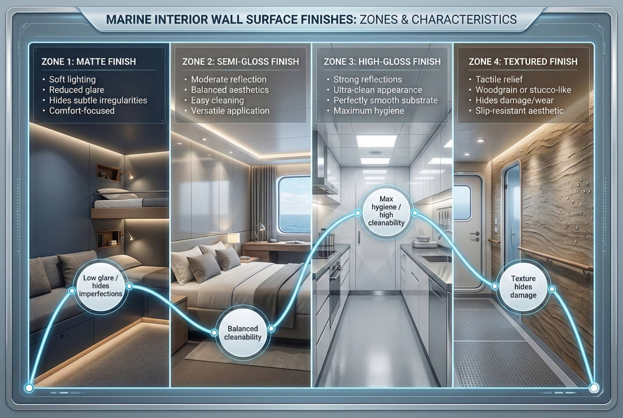
Marine wall panel surface finishes range from matte (5-10% gloss per ASTM D523 at 60° angle, hiding surface imperfections and minimizing glare in crew rest areas), semi-gloss (30-40% gloss, balancing cleanability with moderate light reflection for passenger accommodations), to high-gloss (70-85% gloss, providing maximum cleanability in galleys and hospitals but showing every scratch and requiring perfect substrate preparation). Selection depends on cleaning frequency requirements (high-gloss finishes tolerate aggressive quaternary ammonium disinfectants and high-pressure washing versus matte finishes absorbing stains), lighting conditions (matte reduces glare from low-angle sun in bridge wings and wheelhouses), maintenance philosophy (high-gloss shows wear faster but cleans easier, extending time between repaints from 5-7 years to 8-10 years), aesthetic intent (luxury vessels prefer matte/satin for residential ambiance while functional vessels prioritize gloss for hygiene perception), and substrate imperfections (matte finishes hide 0.2-0.5mm surface irregularities that high-gloss accentuates). Textured finishes (embossed wood grains, leather patterns, stucco effects) add 0.15-0.40mm surface relief hiding minor damage and providing slip resistance in wet areas but complicating deep cleaning.
Gloss Level Classification and Measurement Standards
Surface gloss quantifies light reflection using ASTM D52313 specular reflectance measurement at standardized angles, providing objective finish specification beyond subjective terms like "satin" or "eggshell."
ASTM D523 Measurement Protocol:
- Instrument: Glossmeter with 60° geometry (universal angle for all gloss ranges)
- Calibration: Black glass standard (gloss value = 100 at 60°)
- Sample preparation: Flat panel section, 75mm × 150mm minimum, cleaned with isopropanol
- Measurement: Three readings averaged, controlled temperature (23°C ± 2°C), 50% ± 5% RH
Industry Gloss Classifications:
| Finish Category | 60° Gloss Value (ASTM D523) | Visual Appearance | Light Reflection Character | Typical Marine Applications |
|---|---|---|---|---|
| Flat/Matte | 0-10 | No shine visible, diffuse light scatter | Conceals surface irregularities, minimal glare | Crew quarters, technical spaces, ceiling panels |
| Eggshell | 10-25 | Slight sheen at oblique angles | Moderate diffusion, subtle highlights | Officer cabins, hospital wards |
| Satin/Semi-gloss | 25-40 | Noticeable shine, soft reflections | Balanced diffuse/specular reflection | Passenger cabins, corridors, public restrooms |
| Semi-gloss (high) | 40-70 | Clear reflections of light sources | Primarily specular reflection | Dining rooms, galley prep areas |
| High-gloss | 70-95 | Mirror-like, sharp reflections | Minimal diffusion, strong specular | Commercial galleys, hospital operating prep areas |
The 60° angle standard provides consistency, but extreme gloss values require supplementary measurements: high-gloss finishes (>70 gloss units) add 20° angle measurement for better discrimination, while matte finishes (<10 units) use 85° angle to detect subtle variations.
Gloss Uniformity Requirements: Specifications should mandate ±5 gloss unit variation across panel surfaces. Greater variation creates visually patchy appearance—especially problematic on large unbroken walls (>10m length) where lighting angles reveal inconsistencies.
Gloss Level Impact on Cleanability and Maintenance
Higher gloss finishes provide superior cleanability through reduced surface porosity, but show damage more readily, creating maintenance trade-offs.
Cleaning Performance Testing (per ASTM D4828):
| Gloss Level | Scrub Cycles to Visible Wear | Stain Removal (Coffee, 24hr) | Disinfectant Compatibility | Repaint Frequency (years) |
|---|---|---|---|---|
| Matte (5-10) | 200-500 cycles | 60-75% removal | Moderate (absorbs some chemicals) | 5-7 |
| Satin (30-40) | 800-1200 cycles | 80-90% removal | Good (minimal absorption) | 7-10 |
| Semi-gloss (50-65) | 1500-2000 cycles | 90-95% removal | Excellent (non-porous surface) | 8-12 |
| High-gloss (75-85) | 2500-3500 cycles | 95-99% removal | Excellent (non-porous surface) | 10-15 |
High-gloss finishes tolerate repeated cleaning with quaternary ammonium compounds (common marine disinfectants: Virex, Cavicide) without surface dulling, while matte finishes show gloss increase ("burnishing") after 50-100 cleaning cycles as scrubbing compresses surface texture.
Stain Resistance Mechanisms: Gloss correlates with coating crosslink density and film continuity. High-gloss finishes create non-porous barriers preventing liquid penetration—coffee, wine, or grease sits on the surface enabling easy removal. Matte finishes incorporate flatting agents (silica, talc) creating micro-texture that traps staining liquids, requiring aggressive scrubbing and increasing permanent discoloration risk.
However, high-gloss surfaces reveal every scratch and scuff. Luggage contact in passenger corridors creates visible silver scratches after 6-12 months that matte finishes hide. Maintenance teams report 40-60% more touch-up requests for gloss finishes despite superior cleanability.
Gloss Level Impact on Visual Perception and Aesthetics
Surface gloss dramatically affects spatial perception, lighting quality, and psychological comfort beyond purely functional performance metrics.
Light Reflection and Glare Control:
High-gloss surfaces reflect 70-85% of incident light specularly (mirror-like), creating bright highlights and potential glare sources. In small cabins (8-12 m² crew quarters), gloss finishes amplify artificial lighting, improving perceived spaciousness. However, the same finishes in navigation areas (bridge wings, chart rooms) create distracting reflections interfering with instrument visibility.
Glare Angle Calculations: Direct glare occurs when light source, glossy surface, and observer form angles <30° (specular reflection zone). Morning sun (5-10° above horizon) striking east-facing high-gloss corridors creates severe glare for 1-2 hours daily. Specifications for east/west-facing external accommodation should mandate matte finishes (5-10 gloss) reducing specular reflection by 85-90%.
Color Saturation Effects:
Gloss level affects perceived color intensity through light interaction mechanisms:
- Matte finishes: Diffuse reflection reduces color saturation by 15-25%, creating softer, chalky appearance
- Satin finishes: Balanced reflection maintains color saturation within ±5% of specification
- High-gloss finishes: Specular reflection increases perceived saturation by 10-20%, creating vivid, jewel-like colors
Cruise ship interior designers exploit this: public spaces use high-gloss jewel tones (ruby red, sapphire blue) for visual impact, while passenger cabins employ matte earth tones (taupe, sage) for relaxation. Mismatching gloss to color intent creates aesthetic failures—matte navy blue reads as faded gray, high-gloss beige appears overly stark.
Surface Imperfection Visibility:
| Defect Type | Defect Size | Matte Visibility | Satin Visibility | High-Gloss Visibility |
|---|---|---|---|---|
| Substrate dent | 0.3mm depth | Not visible (diffuse reflection hides) | Slight shadow at oblique angles | Prominent distortion in reflections |
| Orange peel texture | 0.1-0.2mm variation | Not visible | Slightly visible in raking light | Very obvious, unacceptable |
| Dust nibs (cured coating) | 0.2-0.5mm | Rarely noticed | Visible as bumps | Highly visible, requires sanding |
| Sanding scratches | 220-grit pattern | Not visible | Not visible | Visible as swirl marks |
| Color variation | ΔE = 2.0 | Masked by diffuse reflection | Noticeable in uniform lighting | Obvious, creates patchy appearance |
High-gloss specifications require premium substrate preparation—P220 sanding minimum, followed by P320 finish sanding, plus inspection under raking light (light source at 15° to surface) to detect defects. This adds $0.80-1.20/m² preparation cost versus $0.30-0.50/m² for matte finishes.
Textured Surface Finishes and Embossed Patterns
Beyond gloss variation, physical texture adds 0.15-0.40mm surface relief through embossing rollers or patterned coating application, providing functional and aesthetic benefits.
Texture Generation Methods:
Embossed Metal (pre-coating):
- Process: Steel/aluminum facing passes through patterned rollers creating permanent texture
- Depth: 0.15-0.30mm for steel, 0.20-0.40mm for aluminum (greater formability)
- Patterns: Stucco, leather grain, linen weave, geometric patterns
- Cost: +$0.40-0.70/m² versus smooth facing
Embossing occurs before coating application, creating durable texture that won't wear off. However, sharp embossing peaks can telegraph through coating, requiring 120-150 micron minimum total dry film thickness versus 80-100 micron on smooth substrates.
Textured Coatings (post-substrate):
- Process: Coating containing aggregates (silica, polymer beads) applied via spray
- Depth: 0.20-0.50mm depending on aggregate size
- Patterns: Fine sandpaper (180-240 grit equivalent), medium texture (120-150 grit), heavy texture (60-80 grit)
- Cost: +$0.60-1.00/m² versus smooth coating (material + labor)
Textured coatings provide deeper relief than embossing, enhancing slip resistance in wet areas (bathroom walls, shower enclosures). However, deep textures trap dirt in valleys, complicating cleaning and increasing bacterial harbor risk in healthcare areas.
HPL Textured Surfaces:
High-pressure laminates replicate wood grain, stone, and fabric textures through embossing during laminate pressing:
- Registered embossing: Texture aligned with printed pattern (wood grain texture follows printed grain lines)
- Random texture: Generic texture (e.g., leather pebbling) unrelated to print pattern
- Depth: 0.08-0.15mm (shallower than metal embossing due to laminate brittleness)
Registered embossing creates photorealistic wood appearance but costs $4-7/m² more than flat HPL due to precise press alignment requirements.
Functional Texture Applications:
Slip Resistance14 (wet areas):
Embossed or textured finishes reduce slip risk in showers, bathroom walls, and galley splash zones. Testing per ASTM C1028 (Static Coefficient of Friction) shows:
- Smooth high-gloss: COF = 0.25-0.35 (wet), high slip risk
- Light texture: COF = 0.45-0.60 (wet), acceptable
- Medium texture: COF = 0.65-0.80 (wet), excellent
However, regulations classify wall finishes separately from flooring—no minimum COF required. Texture specification remains optional but prudent for areas with water exposure.
Damage Concealment:
Textured surfaces hide minor impacts and scratches by disrupting visual continuity. A 0.3mm dent invisible on stucco-textured matte finish becomes obvious defect on smooth high-gloss. Crew corridors and provision storage areas benefit from medium texture (0.25-0.35mm), reducing cosmetic touch-up frequency by 50-70% versus smooth finishes.
Surface Finish Durability and Environmental Resistance
Surface finish must withstand marine environmental stresses—UV radiation, salt spray, thermal cycling, and chemical cleaners—without degradation over 15-20 year service life.
UV Resistance Testing (per ASTM G154, QUV accelerated weathering):
| Coating Type | Gloss Level | Gloss Retention (2000 hrs) | Yellowing (ΔE) | Chalking Rating | Marine Suitability |
|---|---|---|---|---|---|
| Epoxy | Matte | 80-85% retention | ΔE = 4-6 (moderate yellowing) | Medium (chalking after 1500 hrs) | Interior only |
| Epoxy | High-gloss | 85-90% retention | ΔE = 5-8 (significant yellowing) | Low-medium | Interior only |
| Polyurethane (aliphatic) | Matte | 90-95% retention | ΔE = 1-2 (minimal yellowing) | Minimal | Exterior suitable |
| Polyurethane (aliphatic) | High-gloss | 90-95% retention | ΔE = 1-2 (minimal yellowing) | Minimal | Exterior suitable |
| Acrylic | Semi-gloss | 85-90% retention | ΔE = 2-3 (slight yellowing) | Minimal | Exterior suitable |
| Powder coat (polyester) | Semi-gloss | 75-80% retention | ΔE = 3-5 (moderate) | Medium | Limited exterior use |
Polyurethane topcoats justify 25-40% cost premiums ($0.65-0.90/m² vs. $0.45-0.60/m² for epoxy) on weather-exposed panels through superior UV stability. Epoxy-finished panels on external accommodation require recoating after 5-7 years (yellowing, chalking), while polyurethane extends service to 12-15 years.
Salt Spray Resistance15 (per ASTM B117):
Coating integrity under 5% salt fog exposure simulates marine atmospheric corrosion:
- 1000 hours exposure: Minimum for interior panels (occasional salt spray ingress)
- 3000 hours exposure: Standard for exterior panels (continuous salt air)
- 5000 hours exposure: Premium for weather decks, helicopter hangars (direct seawater contact risk)
Proper coating systems (3-coat: primer + intermediate + topcoat, 220-260 micron total) easily exceed 3000 hours with no rust creep beyond scribe lines. Single-coat systems (<100 micron) fail at 800-1200 hours through undercutting corrosion.
Chemical Resistance Testing16:
Marine cleaning protocols employ aggressive disinfectants creating coating degradation risk:
Common Marine Disinfectants:
- Quaternary ammonium compounds: 400-800 ppm concentration (Virex, Cavicide)
- Sodium hypochlorite: 500-1000 ppm (dilute bleach solutions)
- Phenolic disinfectants: Hospital-grade cleaners (Vesphene, Lysol IC)
- Isopropanol/ethanol: 70% solutions (quick wipes)
Coating Compatibility (per ASTM D1308, immersion testing):
| Coating Type | Quat. Ammonium (24hr) | Bleach 500 ppm (24hr) | Isopropanol (24hr) | High-Pressure Wash (1000 psi) |
|---|---|---|---|---|
| Epoxy (2-part) | Excellent (no effect) | Excellent (no effect) | Good (slight softening) | Excellent (no damage) |
| Polyurethane | Excellent (no effect) | Excellent (no effect) | Excellent (no effect) | Excellent (no damage) |
| Alkyd enamel | Fair (gloss reduction after repeated exposure) | Poor (yellowing, embrittlement) | Fair (softening) | Fair (paint removal at edges) |
| Acrylic latex | Good (minimal effect) | Good (slight fading) | Excellent (no effect) | Good (minimal erosion) |
Two-part epoxy and polyurethane chemistries provide superior chemical resistance justifying specification despite 60-80% cost premiums versus single-component alkyds. Hospital and galley areas subjected to daily disinfection should mandate epoxy or polyurethane exclusively.
Surface Finish Selection by Application Zone
Different vessel areas demand specific finish characteristics based on functional requirements, cleaning intensity, and aesthetic priorities.
Navigation and Bridge Areas:
- Finish: Matte (5-10 gloss), non-reflective
- Color: Dark neutrals (charcoal, navy, forest green) minimizing instrument glare
- Texture: Smooth (texture accumulates dust affecting sensitive electronics)
- Coating: Epoxy sufficient (interior, minimal UV)
- Rationale: Glare control critical for safe navigation, especially night operations with radar/chart plotter illumination
Crew Cabins and Mess Rooms:
- Finish: Matte to satin (10-30 gloss), comfortable ambiance
- Color: Light neutrals (off-white, beige, light gray) maximizing brightness in small spaces
- Texture: Smooth or light embossed (easy cleaning without luxury aesthetic requirements)
- Coating: Epoxy or acrylic (cost-effective for large areas)
- Rationale: Balance economy with adequate cleanability, prioritize psychological comfort over premium appearance
Passenger Cabins (cruise ships):
- Finish: Satin (25-35 gloss), residential aesthetic
- Color: Warm neutrals coordinated with décor schemes
- Texture: HPL wood grain or smooth painted (design-dependent)
- Coating: Polyurethane (durability for 20+ year service)
- Rationale: Hospitality-grade appearance with practical cleanability, minimal glare for sleeping comfort
Public Corridors and Lobbies:
- Finish: Semi-gloss (35-50 gloss), balanced performance
- Color: Vessel branding colors, often vivid hues
- Texture: Light texture concealing traffic wear
- Coating: Polyurethane (high traffic durability)
- Rationale: Compromise between cleanability (frequent spills, contact) and damage concealment (luggage impacts)
Galleys and Food Service:
- Finish: High-gloss (70-85 gloss), sanitation priority
- Color: White or light colors (hygiene perception, shows contamination)
- Texture: Smooth (no dirt traps)
- Coating: Epoxy or stainless steel (chemical resistance)
- Rationale: NSF/ANSI 2 compliance expectations, daily aggressive cleaning with degreasers and disinfectants
Hospitals and Medical Rooms:
- Finish: Semi-gloss to high-gloss (40-70 gloss), cleanability priority
- Color: Soft pastels (pale blue, mint green) or clean white
- Texture: Smooth (bacterial harbor elimination)
- Coating: Polyurethane with antimicrobial additives (BioCote, Microban)
- Rationale: Infection control protocols require non-porous surfaces tolerating bleach-based disinfectants
External Accommodation and Weather Decks:
- Finish: Satin (25-40 gloss), balance durability and glare control
- Color: Light colors (white, cream) reflecting solar heat
- Texture: Light texture (hides weathering)
- Coating: Aliphatic polyurethane mandatory (UV stability)
- Rationale: Direct sunlight exposure causes rapid epoxy yellowing/chalking; polyurethane maintains appearance 10-15 years
Machinery Spaces:
- Finish: Matte to satin (10-30 gloss), industrial aesthetic acceptable
- Color: Functional colors (gray, green, white) often with color-coding for systems
- Texture: Smooth (oil/grease cleanup)
- Coating: Epoxy with chemical resistance (fuel, lubricant exposure)
- Rationale: Prioritize chemical resistance and ease of decontamination over aesthetic refinement
How to evaluate the weight specifications of marine wall panels?
Weight directly impacts vessel stability, fuel efficiency, and structural loading, requiring careful evaluation of panel density, core material contribution, and facing gauge against classification society maximum load limits.
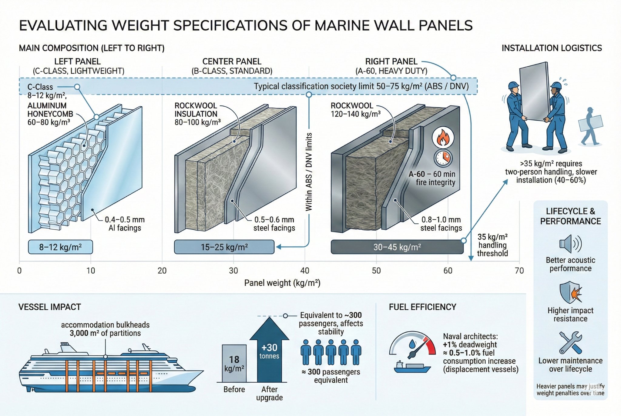
Marine wall panel weight ranges from 8-12 kg/m² for lightweight C-Class panels using aluminum honeycomb cores (density 60-80 kg/m³) with 0.4-0.5mm aluminum facings, through 15-25 kg/m² for standard B-Class panels using rockwool cores (density 80-100 kg/m³) with 0.5-0.6mm steel facings, to 30-45 kg/m² for heavy-duty A-60 panels requiring dense rockwool (120-140 kg/m³) and thick steel facings (0.8-1.0mm) to achieve 60-minute fire integrity. Weight evaluation must consider multiple factors: classification society load limits (typically 50-75 kg/m² maximum distributed load on accommodation bulkheads per ABS/DNV rules), cumulative vessel impact (upgrading 3,000 m² of cruise ship partitions from 18 kg/m² to 28 kg/m² adds 30 tonnes, equivalent to 300 passengers affecting stability calculations), fuel efficiency implications (naval architects estimate 0.5-1.0% fuel consumption increase per 1% deadweight increase on displacement vessels), installation logistics (panels exceeding 35 kg/m² require two-person handling, slowing installation 40-60%), and lifecycle considerations (heavier panels provide better acoustic performance and impact resistance, potentially justifying weight penalties through reduced maintenance).
Panel Weight Component Analysis
Total panel weight derives from three primary components: facing materials, core materials, and adhesive systems. Understanding each contribution enables optimization.
Weight Contribution Breakdown (per m², typical B-15 panel, 50mm thickness):
| Component | Material Specification | Weight (kg/m²) | Percentage of Total | Weight Range (variable factors) |
|---|---|---|---|---|
| Steel facings (both sides) | 0.5mm cold-rolled, two sheets | 7.85-8.00 kg/m² | 45-50% | 6.28 kg/m² (0.4mm) to 11.78 kg/m² (0.8mm) |
| Rockwool core | 50mm, 100 kg/m³ density | 5.00 kg/m² | 28-32% | 3.00 kg/m² (60 kg/m³) to 7.00 kg/m² (140 kg/m³) |
| Adhesive layers | Two-component polyurethane | 0.80-1.20 kg/m² | 5-7% | 0.60 kg/m² (thin film) to 1.50 kg/m² (thick application) |
| Edge sealant/trim | Steel channel edges | 0.50-0.80 kg/m² | 3-5% | 0.30 kg/m² (minimal) to 1.20 kg/m² (heavy frame) |
| Coating system | 3-coat epoxy, 240 micron DFT | 0.35-0.50 kg/m² | 2-3% | 0.20 kg/m² (single coat) to 0.65 kg/m² (heavy texture) |
| Total Standard Panel | B-15, 50mm, steel facings | 14.50-15.50 kg/m² | 100% | 10.38-22.13 kg/m² (full range) |
Steel facings dominate weight—reducing from 0.6mm to 0.5mm saves 1.57 kg/m², but compromises fire rating from A-0 to B-15. Core density variations (60-140 kg/m³) impact weight by ±2.0 kg/m² while maintaining fire performance through chemistry adjustments (higher melting point fibers compensate for lower density).
Facing Material Weight Calculations:
Steel facing weight follows formula: W = ρ × t × 2 (kg/m²), where ρ = 7,850 kg/m³ (steel density), t = thickness (mm), factor 2 accounts for both sides.
- 0.4mm steel facings: 7.85 × 0.4 × 2 = 6.28 kg/m²
- 0.5mm steel facings: 7.85 × 0.5 × 2 = 7.85 kg/m²
- 0.6mm steel facings: 7.85 × 0.6 × 2 = 9.42 kg/m²
- 0.8mm steel facings: 7.85 × 0.8 × 2 = 12.56 kg/m²
Aluminum facings (ρ = 2,700 kg/m³) provide 66% weight reduction:
- 0.5mm aluminum facings: 2.7 × 0.5 × 2 = 2.70 kg/m² (saves 5.15 kg/m² versus steel)
- 0.7mm aluminum facings: 2.7 × 0.7 × 2 = 3.78 kg/m² (saves 4.07 kg/m² versus 0.5mm steel)
However, aluminum's lower fire resistance restricts use to C-Class and some B-Class applications after extensive testing—weight savings must not compromise safety.
Core Material Weight Calculations:
Core weight follows W = ρ_core × t_core (kg/m²), where ρ_core = core density (kg/m³), t_core = core thickness (mm = m/1000).
- 50mm, 80 kg/m³ rockwool: 80 × 0.050 = 4.00 kg/m²
- 50mm, 100 kg/m³ rockwool: 100 × 0.050 = 5.00 kg/m²
- 50mm, 120 kg/m³ rockwool: 120 × 0.050 = 6.00 kg/m²
- 75mm, 100 kg/m³ rockwool: 100 × 0.075 = 7.50 kg/m² (A-60 rating)
Aluminum honeycomb cores (60-80 kg/m³) at 50mm thickness weigh only 3.0-4.0 kg/m², saving 1.0-3.0 kg/m² versus rockwool, but provide no fire insulation—acceptable only in C-Class non-fire-rated partitions.
Weight Impact on Vessel Performance and Operations
Panel weight affects multiple vessel performance parameters beyond simple material cost, creating cascading effects through design and operations.
Stability and Center of Gravity:
Accommodation superstructures sit high above waterline, with panel weight contributing to vessel's vertical center of gravity (VCG). Naval architects calculate stability through metacentric height (GM): GM = KB + BM - KG, where KG (vertical center of gravity) increases with superstructure weight.
Weight Impact Example (5000 GT coastal ferry):
- Scenario: Replace 3,500 m² accommodation partitions
- Original specification: 22 kg/m² (A-0 heavy-duty), total 77,000 kg
- Lightweight alternative: 16 kg/m² (B-15 optimized), total 56,000 kg
- Weight savings: 21,000 kg (21 tonnes)
- VCG impact: Assuming 8m height above keel, reduces KG × weight moment by 168 tonne-meters
This 21-tonne reduction enables either: (1) adding 210 passengers (100 kg each) without stability recalculation, (2) reducing ballast by 15-18 tonnes saving fuel, or (3) improving stability margins providing operational safety buffer in rough seas.
Classification societies mandate stability analyses whenever modifications exceed 2% of lightship weight. On 1,200-tonne lightship ferry, 21-tonne panel change (1.75%) avoids recalculation requirement, but 30-tonne change (2.5%) triggers full inclining test costing $15,000-25,000.
Fuel Consumption Impact:
Vessel fuel consumption correlates directly with displacement through Admiralty coefficient and specific fuel consumption relationships. Industry estimates suggest 0.5-1.0% fuel increase per 1% deadweight increase, though actual impact varies with hull form and speed.
Fuel Impact Calculation (10,000 GT cargo vessel):
- Lightship weight: 3,500 tonnes
- Panel weight increase: 15 kg/m² to 22 kg/m² across 5,000 m² (35 tonnes added)
- Percentage increase: 35/3,500 = 1.0% lightship increase
- Annual fuel consumption: 1,800 tonnes HFO (180 days at sea, 10 tonnes/day)
- Fuel increase: 1.0% × 0.75% sensitivity = 0.75% increase = 13.5 tonnes/year
- Cost impact: 13.5 tonnes × $650/tonne = $8,775/year additional fuel cost
Over 20-year panel lifespan, cumulative fuel cost penalty reaches $175,500 (undiscounted)—potentially exceeding the $85,000-120,000 initial cost savings from heavier, cheaper panels. Lifecycle cost analysis must account for operational impacts, not just procurement pricing.
Structural Loading Limits:
Classification societies specify maximum distributed loads for accommodation bulkheads and deckheads based on structural scantlings and stiffener spacing.
Typical Maximum Loads (per ABS, DNV-GL, Lloyd's Register rules):
| Location | Structural Support | Maximum Distributed Load | Maximum Point Load | Safety Factor |
|---|---|---|---|---|
| Accommodation bulkhead, welded to deck/frames | Vertical stiffeners @ 600mm spacing | 50-75 kg/m² | 150-200 kg (concentrated load) | 1.5-2.0 |
| Accommodation bulkhead, clip-attached | Vertical stiffeners @ 600mm spacing | 40-60 kg/m² | 100-150 kg | 1.5-2.0 |
| Deckhead (ceiling), suspended | Hanger rods @ 1200mm grid | 25-40 kg/m² | 50-80 kg | 2.0-2.5 |
| Fire division bulkhead, A-Class | Continuous welded frame | 60-90 kg/m² | 200-300 kg | 1.5-2.0 |
Standard 15-20 kg/m² panels operate well within limits, but heavy-duty A-60 panels (30-40 kg/m²) approach maximum loads when considering attachment hardware, insulation, and mounted equipment (cabinets, shelves, TV brackets). Exceeding limits requires structural reinforcement—adding stiffeners or reducing spacing from 600mm to 450mm, increasing steel weight and cost by 25-40%.
Installation Labor Impact:
Panel weight directly affects installation labor productivity and safety requirements.
Handling Requirements by Weight Class:
| Panel Weight | Handling Method | Installation Rate (m²/hr, 2-person crew) | Safety Equipment | Fatigue Factor |
|---|---|---|---|---|
| 8-15 kg/m² | Single-person carry (panels <2.4m height) | 12-15 m²/hr | Basic PPE (gloves, boots) | Low |
| 15-25 kg/m² | Two-person carry | 9-12 m²/hr | Basic PPE | Moderate |
| 25-35 kg/m² | Two-person carry, lifting straps | 7-9 m²/hr | Lifting straps, back support | High |
| 35-50 kg/m² | Mechanical assist (hoist, cart) | 5-7 m²/hr | Hoist/crane, lifting equipment | Very high |
Projects specifying heavy panels (>30 kg/m²) experience 40-60% productivity reduction versus lightweight alternatives, directly increasing labor costs. A 3,000 m² retrofit at $12-18/m² installed labor using 18 kg/m² panels costs $36,000-54,000, while equivalent project with 35 kg/m² panels increases to $52,000-75,000—additional $16,000-21,000 purely from weight-driven inefficiency.
Weight Optimization Strategies
Achieving minimum weight while maintaining required fire ratings and structural integrity requires systematic optimization across all panel components.
Strategy 1: Minimum-Gauge Facings for Fire Class
Specify thinnest steel facings meeting fire rating requirements:
- B-15/B-0: 0.5mm steel (7.85 kg/m²) instead of default 0.6mm (9.42 kg/m²), saves 1.57 kg/m²
- A-0: 0.6mm steel (9.42 kg/m²) instead of conservative 0.7mm (10.99 kg/m²), saves 1.57 kg/m²
- A-15: Verify if 0.7mm passes test versus default 0.8mm specification
Requires obtaining actual test reports confirming minimum gauge—many suppliers specify thicker facings than necessary for manufacturing convenience rather than certification requirements.
Strategy 2: Optimized Core Density
Select lowest density rockwool passing fire test for specific panel thickness:
- 50mm B-15: Test confirms 80 kg/m³ sufficient versus conservative 100 kg/m³ specification, saves 1.0 kg/m²
- 60mm A-0: Use 90 kg/m³ instead of 110 kg/m³, saves 1.2 kg/m²
- 75mm A-30: Specify 100 kg/m³ with high-temperature binder versus 120 kg/m³ standard grade, saves 1.5 kg/m²
Requires supplier providing test data correlating density, thickness, and fire performance—not all manufacturers optimize these parameters.
Strategy 3: Aluminum Substitution (Non-Fire Areas)
Replace steel facings with aluminum in C-Class areas without fire rating requirements:
- 0.5mm aluminum (2.70 kg/m²) versus 0.5mm steel (7.85 kg/m²) saves 5.15 kg/m²
- Applications: Interior cabin partitions (not escape routes), storage room divisions, office partitions
Limitations: Classification societies may restrict aluminum use even in C-Class areas due to smoke/toxicity concerns. Always verify acceptance before specifying.
Strategy 4: Honeycomb Core Non-Fire Panels
Aluminum honeycomb cores provide maximum weight savings where fire ratings unnecessary:
- 25mm aluminum honeycomb panel with 0.5mm aluminum facings: 6-8 kg/m² total
- Savings versus rockwool: 7-9 kg/m² (50-60% reduction)
- Applications: Joinery partitions, furniture panels, non-structural divisions
However, honeycomb provides no fire resistance and minimal acoustic insulation—unsuitable for accommodation separation.
Strategy 5: Panel Thickness Reduction
Reducing thickness from 50mm to 40mm (where acoustic performance allows) cuts core weight by 20%:
- 50mm, 100 kg/m³ rockwool: 5.00 kg/m²
- 40mm, 100 kg/m³ rockwool: 4.00 kg/m² (saves 1.0 kg/m²)
Suitable for secondary divisions (storage rooms, technical spaces) where acoustic isolation less critical. Not applicable to cabin-to-cabin partitions requiring STC 40+ ratings.
Combined Optimization Example:
Original specification (conservative, no optimization):
- Facings: 0.6mm steel both sides = 9.42 kg/m²
- Core: 50mm, 110 kg/m³ rockwool = 5.50 kg/m²
- Adhesive/edge: 1.00 kg/m²
- Total: 15.92 kg/m²
Optimized specification (B-15 fire rating maintained):
- Facings: 0.5mm steel both sides = 7.85 kg/m²
- Core: 50mm, 85 kg/m³ rockwool = 4.25 kg/m²
- Adhesive/edge: 0.80 kg/m²
- Total: 12.90 kg/m²
Weight savings: 3.02 kg/m² (19% reduction)
Project savings (3,000 m²): 9,060 kg (9.06 tonnes)
Fuel savings (20-year lifecycle): Estimated 0.25% consumption reduction = $3,500-5,000/year = $70,000-100,000 total
Weight Documentation and Verification
Specifications must clearly define weight limits and verification methods to ensure suppliers deliver conforming products.
Specification Weight Clause (recommended format):
"Panel weight shall not exceed XX kg/m² ±5% as measured per ASTM C36717 (mass per unit area). Manufacturer shall provide certified weight certificates based on testing of minimum five (5) random panels per production batch. Weight verification testing shall occur in presence of Owner's representative or approved third-party inspector. Panels exceeding specified weight by >5% shall be rejected and replaced at Contractor's expense."
Weight Testing Procedure (per ASTM C367):
- Select random panel from production batch
- Measure panel dimensions (length × width) to ±1mm accuracy, calculate area in m²
- Weigh panel on calibrated scale (±0.1 kg accuracy)
- Calculate weight per m²: W = measured_weight / area
- Repeat for five panels, average results
- Verify average ≤ specification limit and all individual values within ±5% of average
Common Weight Specification Errors:
- Nominal thickness vs. actual: Specifying "50mm panel, 15 kg/m²" without clarifying whether thickness includes facings (total assembly) or core only. Actual assembled thickness often reaches 52-54mm with facings and adhesive, increasing weight 4-8% versus core-only calculations.
- Excluding edge treatments: Weight limits stated without clarifying if steel edge channels (adding 0.5-1.2 kg/m²) are included. Panels passing bare weight limits may exceed specification after edge finishing.
- Coating weight omission: Specifications stating "substrate weight" without clarifying if coating system (0.2-0.6 kg/m²) counts toward limit. Heavy texture coatings can push compliant substrates over limits.
- Tolerance stacking: Allowing ±5% tolerance on facings, ±5% on core, and ±5% on total weight enables 15% cumulative overrun through specification loopholes.
Best Practice: Specify "total installed weight including all facings, core, adhesives, edge treatments, and coating systems" with single ±3% tolerance on final assembly to eliminate ambiguity.
How to choose the right certification for marine wall panels?
Choosing correct certification prevents project delays, ensures legal compliance, and avoids costly rework when panels fail flag state or port state control inspections during vessel operation.
Marine wall panel certification selection must match four critical requirements: vessel flag state approval (certification must be accepted by vessel's registration country—Panama, Liberia, Marshall Islands, etc.), intended installation location classification (SOLAS defines bulkhead requirements by zone: passenger accommodation, crew areas, service spaces, machinery spaces), operational trade routes (EU MED certification mandatory for vessels operating European waters regardless of flag, IMO Polar Code compliance for Arctic/Antarctic routes), and classification society recognition (certifications must appear on ABS, DNV-GL, Lloyd's Register, Bureau Veritas, or relevant society's approved product lists). Selection errors create immediate consequences: non-flag-approved products trigger survey rejections requiring panel replacement before sea trial completion, missing zone-specific certifications (e.g., A-60 tested only for vertical bulkheads but specified for deckheads) void insurance coverage if fire occurs, absent regional certifications like MED prevent vessel entry to EU ports facing detention and daily penalties of $25,000-50,000, and unapproved materials discovered during port state inspections result in deficiency notices requiring correction within 14 days or vessel detention.
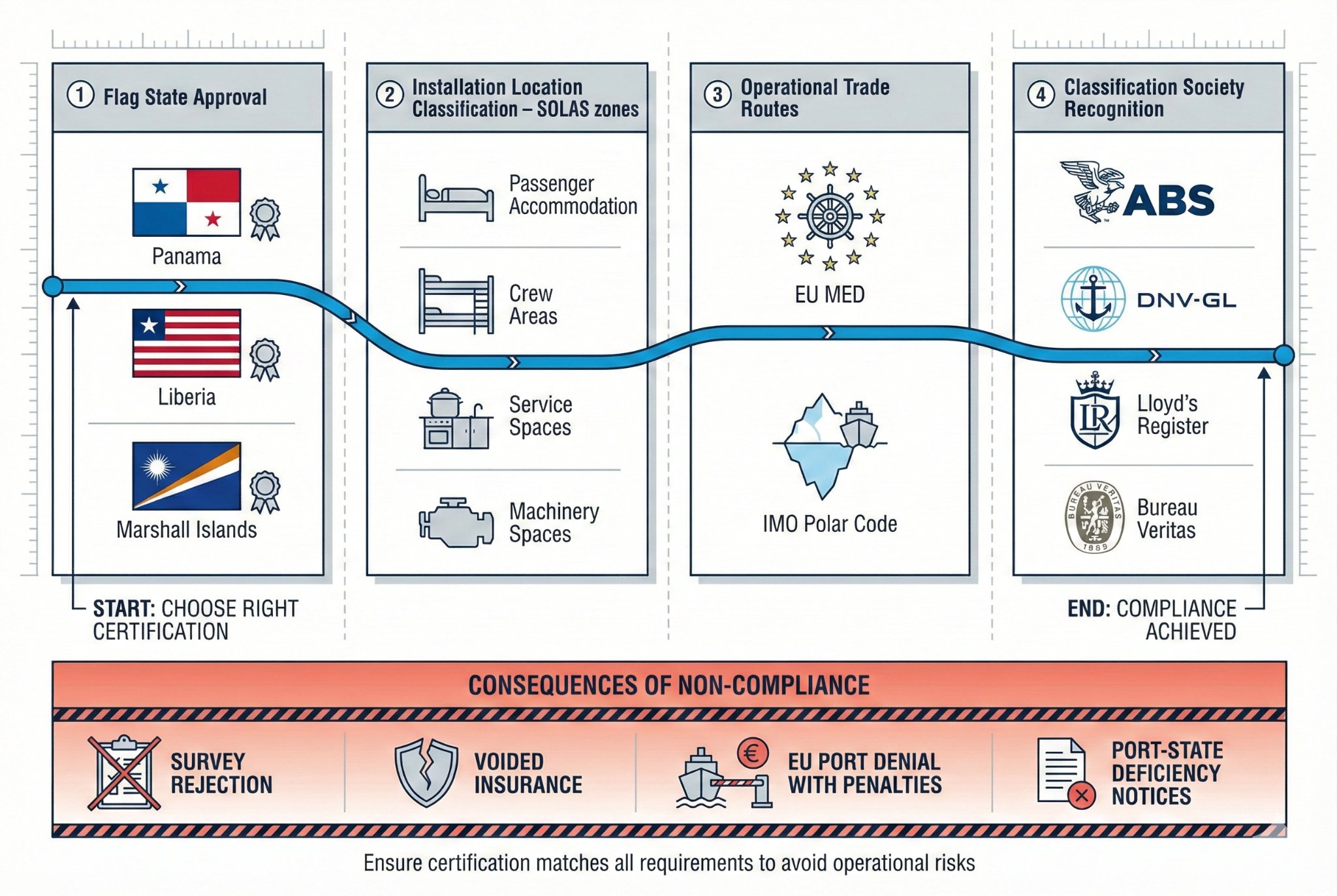
Understanding certification hierarchy and selection criteria prevents specification errors that surface only during final vessel inspections when correction costs escalate 10-20 times versus procurement phase adjustments.
Flag State Certification Requirements
Flag state approval forms the primary certification requirement—panels must carry approval from vessel's registration country or internationally recognized equivalent certification accepted through reciprocal agreements.
Major Flag State Certification Systems:
| Flag State | Approval Authority | Acceptance of Other Certifications | Typical Processing Time | Validity Period | Renewal Requirements |
|---|---|---|---|---|---|
| Panama | Autoridad Marítima de Panamá (AMP) | Accepts IACS member society approvals (ABS, DNV, Lloyd's, etc.) automatically | 2-4 weeks (if IACS approved) | 5 years | Resubmit test reports, no retest required |
| Liberia | Liberian International Ship Registry (LISR) | Accepts IMO/IACS approvals, requires registration | 3-6 weeks initial registration | 5 years | Annual product registration fee $500-800 |
| Marshall Islands | Maritime Administrator (RMI) | Accepts all IACS society approvals without separate registration | Immediate (if IACS approved) | Follows IACS certificate | No separate renewal |
| Bahamas | Bahamas Maritime Authority | Accepts IACS approvals plus specific IMO certificates | 2-4 weeks verification | 5 years | Document update only |
| Malta | Transport Malta | Requires EU MED + IACS approval | 4-8 weeks (includes MED verification) | 5 years | MED renewal triggers Malta renewal |
| Singapore | Maritime and Port Authority (MPA) | Accepts IACS approvals, strict documentation requirements | 6-10 weeks initial approval | 3 years | Resubmission with updated tests |
IACS Recognition Advantage:
Products certified by International Association of Classification Societies (IACS) members gain automatic or simplified acceptance by 80-90% of flag states through mutual recognition agreements. IACS members include ABS (USA), DNV-GL (Norway), Lloyd's Register (UK), Bureau Veritas (France), ClassNK (Japan), RINA (Italy), CCS (China), KR (South Korea), Indian Register, and Polish Register.
Non-IACS Flag States:
Some flag states (primarily landlocked nations offering "flag of convenience" registration) issue their own certifications through contracted inspection bodies. These certifications face scrutiny during port state controls—EU and US Coast Guard inspectors often require additional verification when encountering non-IACS certifications, increasing inspection duration and detention risk.
Flag State Selection Impact on Certification:
Shipowners choose flag states based on registration costs, taxation, crew nationality requirements, and international acceptance—but this choice directly impacts panel certification requirements:
- Panama flag (25% of world fleet): Straightforward—accepts all IACS approvals, panels certified by ABS, DNV, Lloyd's, BV require no additional documentation.
- Liberia flag (11% world fleet): Requires product registration with LISR but accepts IACS testing—adds $500-800 registration fee and 3-6 week processing versus Panama.
- Marshall Islands (13% world fleet): Most flexible—accepts IACS approvals instantly without registration fees or processing time.
- Malta flag (EU flag, 6% world fleet): Requires EU MED certification mandatory for all construction products—adds €3,000-8,000 per product line and 6-12 month certification process versus non-EU flags.
Specification Strategy:
When flag state unknown during design phase (common for speculative shipyard construction), specify panels certified by minimum two IACS member societies from different regions (e.g., ABS + Lloyd's or DNV + BV) ensuring 95%+ probability of flag state acceptance regardless of final registration choice.
SOLAS Zone-Based Certification Requirements
SOLAS Chapter II-2 defines vessel fire safety zones with distinct certification requirements based on fire risk level and escape route significance.
SOLAS Fire Safety Zones and Panel Requirements:
| SOLAS Zone | Description | Required Fire Rating | Additional Testing | Certification Scope |
|---|---|---|---|---|
| Category A Space | Accommodation, service spaces, control stations | A-60, A-30, A-15, A-0 depending on function | IMO FTP Code Part 3 (bulkheads), Part 4 (linings), smoke/toxicity per Part 2 | Bulkhead + ceiling certification both required |
| Category B Space | Same as A, lower fire risk (fewer than 12 passengers) | A-0, B-15, B-0 | Smoke/toxicity Part 2 | Bulkhead certification mandatory, ceiling may use lower rating |
| Category C Space | Public spaces, passenger/crew accommodation | A-60, A-30, A-0 depending on adjacency | Part 2, 3, 4 plus surface spread of flame | Full lining system approval (panels + installation method) |
| Machinery Spaces | Engine rooms, boiler rooms | A-60 boundaries minimum | Heat resistance, vibration, humidity cycling | Special machinery space approval, standard panel certs insufficient |
| Escape Routes | Corridors, stairways, evacuation paths | A-60 or A-30 boundaries | Low flame spread (≤25 FSI), ultra-low smoke (≤50 Ds @ 4 minutes) | Stringent smoke criteria, many standard A-rated panels fail |
| Service Spaces (high risk) | Galleys, pantries, laundries, saunas | A-60 boundaries to accommodation | Grease/moisture resistance, cleanability testing | Standard fire certs plus hygiene approvals (NSF, IMO Hygiene) |
Certification Scope Verification (Critical Detail):
Fire test certificates specify exact test configuration—"A-60 bulkhead test" certification doesn't automatically permit same panel for A-60 deckheads (ceilings) because heat exposure pattern differs:
- Bulkhead test: Fire exposure from one side (furnace on side A, temperature measurement on side B)
- Deckhead test: Fire exposure from below (furnace underneath, temperature measurement on upper surface)
- Deck test: Fire exposure from above (furnace on top surface, temperature measurement on underside)
Deckhead applications trap heat against ceiling, creating more severe temperature rise than vertical bulkheads—25-40°C higher on unexposed surface after 30 minutes. Many panels passing A-30 bulkhead tests fail A-30 deckhead tests, requiring specification of separately certified products.
Specification Error Example:
Project specifies "A-30 marine wall panels, 5,000 m²" for mixed application including 3,500 m² bulkheads and 1,500 m² deckheads. Supplied panels carry only "A-30 bulkhead" certification. During flag state survey, inspector rejects 1,500 m² deckhead installation requiring replacement with properly certified deckhead panels—additional cost $75,000-105,000 (1,500 m² × $50-70/m²) plus 2-3 week schedule delay.
Prevention: Specifications must state application: "A-30 bulkhead certification for bulkheads (3,500 m²)" and "A-30 deckhead certification for ceilings (1,500 m²)" as separate line items with distinct products.
IMO FTP Code and ISO Fire Testing Certification
IMO Fire Test Procedures (FTP) Code defines international fire testing standards for marine construction materials, superseding earlier SOLAS regulations with performance-based requirements.
Primary FTP Code Testing Requirements for Marine Panels:
Part 1 – Non-Combustibility Test (ISO 1182):
- Purpose: Determines if material is "non-combustible" under SOLAS definition
- Test method: 750°C furnace exposure, 30-minute duration
- Pass criteria: Temperature rise ≤50°C above furnace temperature, mass loss ≤50%, no sustained flaming >10 seconds
- Applicable materials: Facing materials (steel, aluminum, treated steel), core materials claiming non-combustibility
- Typical results: Steel facings pass easily, rockwool core passes, mineral wool passes, glass wool borderline (some products fail mass loss criterion)
Part 2 – Smoke and Toxicity Testing:
- Test standards: ISO 5659-2 (smoke density), ISO 5660-1 (heat release rate)
- Key parameters:
- Specific optical density (Ds): Maximum 100 at 1.5 minutes, 200 at 4 minutes (passenger ships)
- Total heat release: ≤0.75 MJ/m² over 10 minutes (non-combustible), ≤1.5 MJ/m² (combustible surface finishes)
- Toxicity index: CO, CO₂, HCl, HCN, SO₂ measured, weighted toxic gas index must be ≤5
- Critical for: All visible surfaces, especially escape route linings
- Common failures: Organic coatings (polyurethane, acrylic) exceed smoke limits; phenolic binders in some mineral wools produce HCN exceeding toxicity limits
Part 3 – Fire Resistance Test (ISO 834):
- Purpose: Measures structural integrity, insulation, and flame penetration resistance
- Duration: 15, 30, or 60 minutes (A-15, A-30, A-60)
- Pass criteria:
- Structural integrity: No through-cracks, holes, or collapses
- Insulation: Unexposed surface temperature rise ≤140°C average, ≤180°C any single point
- Flame penetration: No sustained flaming on unexposed side
- Test specimen size: Minimum 3m × 3m bulkhead assembly or 3m × 4m deck/deckhead assembly
- Loading requirements: Bulkheads tested with 10 kN/m² vertical load simulating above-deck loading
Part 4 – Combustible Material Test:
- Applies to: Surface finishes, decorative panels, joinery materials
- Key test: Room corner test (ISO 9705) measuring fire growth and flashover
- Pass criteria:
- No flashover within test duration
- Heat release rate (HRR) ≤100 kW average over first 10 minutes
- Total heat release ≤15 MJ for small ignition source
- Rarely required for: Basic accommodation partitions (covered by Part 3), but mandatory for decorative wall panels with wood veneer, laminate, or fabric finishes
Certification Documentation Requirements:
Complete FTP Code certification includes:
- Test report: Full laboratory report (30-80 pages) describing test setup, specimen construction (exact materials, thicknesses, densities), test observations, temperature/smoke data, calculations
- Product certificate: Summary document (2-4 pages) from classification society confirming test compliance and listing approved applications
- Drawings: Technical drawings showing tested assembly including fastening methods, joint details, edge treatments
- Declaration of conformity: Manufacturer's signed statement that supplied products match tested configuration
Common Specification Error:
Accepting manufacturer's certificate of conformity without reviewing actual test reports. Discrepancies between tested configuration and supplied products often hidden:
- Test report specifies 0.6mm steel facings, but supplied product uses 0.5mm steel (thinner gauge may fail)
- Test uses 110 kg/m³ rockwool core, supplier provides 90 kg/m³ (lower density reduces insulation performance)
- Test assembly includes steel edge channels, supplier delivers panels with aluminum edges (different thermal expansion)
Verification requirement: Request complete test reports and compare specifications line-by-line to purchase order specifications before accepting materials.
EU MED and Regional Certification Requirements
Vessels operating European waters require Marine Equipment Directive (MED) certification regardless of flag state—failure to comply results in port entry denial and daily detention penalties.
EU MED Certification (2014/90/EU):
Scope and Applicability:
- Mandatory for: All ships entering EU ports (including non-EU flagged vessels)
- Covered products: Fire doors, dampers, structural fire protection (including marine wall panels), lifesaving equipment, navigation equipment, pollution prevention equipment
- Marking requirement: Products must display "wheelmark" (ship's wheel symbol) with notified body identification number
MED Certification Process for Marine Panels:
- Module B (Type Examination): Notified body reviews test reports (IMO FTP Code tests accepted), inspects production facility, issues EU Type Examination Certificate—cost €5,000-12,000, duration 3-6 months
- Module D (Quality Assurance): Notified body audits manufacturer's ISO 9001 quality system, conducts annual surveillance audits—cost €3,000-5,000/year
- Certificate validity: 5 years with annual surveillance audits required
- Product marking: Each panel receives wheelmark label with notified body number (e.g., "⎈0575" for Bureau Veritas)
Notified Bodies (selection matters):
Twenty-six organizations hold MED notified body status, but five dominate marine panel certification:
- Bureau Veritas (0575): France-based, 15-20% lower fees, 12-16 week processing
- Lloyd's Register (0038): UK-based (Brexit requires EU subsidiary), premium pricing, 10-14 week processing, highest industry recognition
- DNV-GL (0575): Norway-based, comprehensive services, 12-18 week processing
- RINA (0474): Italy-based, competitive pricing for Italian/Mediterranean shipyards, 14-20 week processing
- TÜV (Notified body numbers vary): Germany-based, multiple entities (TÜV SÜD, TÜV Rheinland), 16-22 week processing
Cost Impact:
EU MED certification adds €8,000-17,000 per product line (initial certification) plus €3,000-5,000 annual surveillance costs. For panel suppliers serving only non-EU markets, this expense (€50,000-85,000 for five product lines over five years) may not justify European market access unless projected sales exceed €500,000-800,000.
Specification Strategy for EU-Operating Vessels:
- Firm requirement: "All marine wall panels must carry valid EU MED certification (wheelmark) with current Type Examination Certificate and annual surveillance audit verification."
- Supplier verification: Request copy of MED certificate, confirm notified body number matches wheelmark label, verify certificate covers specified fire ratings and panel constructions
- Warning sign: Suppliers claiming "IMO approval sufficient for Europe"—legally incorrect, guarantees detention if discovered during port state control
Other Regional Requirements:
US Coast Guard (USCG) Approval:
- Applicability: US-flagged vessels, vessels regularly calling US ports
- Process: USCG Marine Safety Center reviews IMO test reports, issues approval letter, adds product to approved equipment list
- Duration: 10-15 weeks processing, 5-year validity
- Cost: $2,500-4,500 USCG review fee plus consultant fees $3,000-6,000
IMO Polar Code (2017):
- Applicability: Vessels operating Arctic (>60°N) or Antarctic (>60°S) waters
- Additional requirements: Low-temperature fire testing (-30°C to -50°C environment), cold weather durability (thermal shock, ice loading), materials must maintain fire resistance at extreme cold
- Testing additions: ISO 834 fire test repeated at -30°C ambient, insulation performance verified after 200 freeze-thaw cycles
- Cost: $15,000-25,000 additional testing per product, 6-9 month lead time
- Certification bodies: DNV-GL, Lloyd's Register (limited facilities capable of combined fire/cold testing)
China CCS (China Classification Society) Approval:
- Mandatory for: Vessels built in Chinese shipyards (70% of global newbuild market share)
- Process: CCS reviews IMO test reports, conducts factory inspection, issues product certificate
- Peculiarity: CCS often requires witnessing factory production runs even when IACS certificates exist—adds 2-4 week lead time
- Cost: ¥8,000-15,000 ($1,100-2,100) initial approval plus ¥3,000-5,000 annual surveillance
- Strategic importance: Without CCS approval, panels cannot be supplied to Chinese shipyards regardless of other certifications
IMO Noise Code (Resolution MSC.337(91)):
- Applies to: Accommodation bulkheads, deck/deckhead assemblies in crew/passenger areas
- Requirement: Sound transmission loss ≥35-45 dB depending on space adjacency
- Testing: ISO 140-3 or ASTM E90 in accredited acoustic laboratory
- Certification: Separate acoustic certificate required, not covered by fire testing
- Cost: $4,000-8,000 per assembly configuration
Specification Matrix for Multi-Regional Operations:
| Trade Route | Required Certifications | Critical Check | Lead Time Impact | Cost Adder |
|---|---|---|---|---|
| Europe only | MED + IACS member society | Wheelmark labeling, notified body surveillance current | +3-6 months initial | +€8,000-17,000 |
| US only | USCG approval + IACS | USCG approval letter, equipment list entry | +10-15 weeks | +$5,500-10,500 |
| Europe + US | MED + USCG + IACS | Both regional approvals valid, no expiry conflicts | +5-8 months initial | +€15,000-27,000 |
| China-built | CCS + IACS (MED if EU-trading) | CCS factory inspection completed, product certificate issued | +6-10 weeks | +¥11,000-20,000 |
| Polar routes | IMO Polar + standard certs | Low-temp fire test, cold durability verification | +6-9 months testing | +$15,000-25,000 |
| Global trading | MED + USCG + CCS + IACS + Polar (if applicable) | All certifications valid for 5+ years, staggered renewal dates avoided | +8-14 months initial | +$35,000-60,000 |
Renewal Management Strategy:
Certifications expire on different cycles (MED: 5 years, USCG: 5 years, CCS: annual surveillance, Polar: 5 years, flag state: varies). Aligning renewal dates prevents situation where vessel operates with partially expired certifications:
- Best practice: Schedule all major certifications (MED, USCG, IACS) with same expiry month ±3 months to enable single renewal campaign
- Renewal lead time: Begin renewal process 12-15 months before expiry (test report review 6 months, new testing if standards changed 6-9 months, certification body processing 2-4 months)
- Cost consideration: Renewal without retesting (when standards unchanged): 40-60% of initial certification cost; renewal with retesting (when IMO updates FTP Code): 80-100% of initial cost
Conclusion
Marine wall panel selection requires balancing eight interdependent parameters—fire class, thickness, core material, sound reduction, facing material, surface finish, weight, and certification—where each decision impacts vessel safety, regulatory compliance, and operational costs. Systematic evaluation across all dimensions prevents costly specification errors that surface during surveys, installations, or port inspections.
-
Learn about STC to ensure adequate sound insulation in passenger accommodations and improve comfort. ↩
-
Understanding ISO 5774 ensures proper integration of door frames with panel thickness for safety and efficiency. ↩
-
Learn about ASTM E136 to understand how it sets standards for incombustibility in materials. ↩
-
Discover the role of calcium silicate boards in enhancing fire resistance and structural integrity. ↩
-
Understanding compression strength is vital for ensuring durability and performance in high-traffic areas. ↩
-
Learn about the advantages of Cold-rolled steel for durability and cost-effectiveness. ↩
-
Discover the benefits of galvanized steel for corrosion resistance in marine applications. ↩
-
Understanding corrosion resistance is crucial for selecting materials for marine environments. ↩
-
Understand the advantages of this aluminum alloy for weight reduction and performance. ↩
-
Discover how HPL can transform functional panels into attractive architectural elements. ↩
-
Understanding the flame spread index helps in selecting safe materials for construction. ↩
-
Learn about materials that can withstand impacts and ensure longevity in marine applications. ↩
-
Understanding ASTM D523 is crucial for accurate gloss measurement and finish specification. ↩
-
Slip resistance is crucial for safety; explore how it's tested and specified. ↩
-
Learn about salt spray resistance testing to ensure coatings withstand marine environments. ↩
-
Explore the importance of chemical resistance testing to ensure coatings endure harsh cleaning agents. ↩
-
Exploring ASTM C367 will provide insights into standardized testing methods for accurate weight verification. ↩