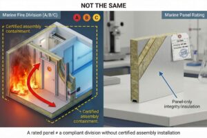
A warped marine fire door isn't just an eyesight problem—it compromises watertight integrity, fails fire safety inspections, and puts crew lives at risk during emergencies.
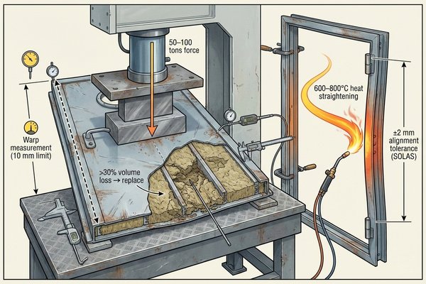
Fixing a warped marine fire door involves a systematic approach covering all warping types: Remove the door from its frame, assess the core material damage (steel frame distortion, rockwool compression, or door leaf bending), apply targeted correction methods (heat straightening for steel frames at 600-800°C, core material replacement for moisture-damaged insulation, hydraulic pressing for door leaf straightening at 50-100 tons force), reinstall with proper alignment checks (±2mm tolerance per SOLAS requirements), and conduct mandatory fire integrity testing. For warping exceeding 10mm or core material degradation beyond 30% volume, full door replacement is the only compliant solution.
This guide walks through proven correction techniques I've applied across Southeast Asian shipyards, from minor frame adjustments to complete door reconstruction, ensuring compliance with IMO Resolution A.754(18) fire test standards.
What Causes Marine Fire Doors to Warp in the First Place?
Warping doesn't happen randomly—it's the direct result of environmental stress, installation errors, or material failure that accumulates over months of operation.
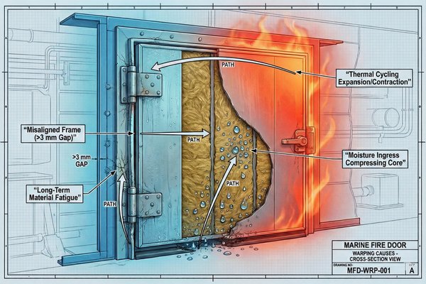
Marine fire door warping originates from four primary causes: thermal cycling stress (repeated heating/cooling cycles causing steel frame expansion at 12×10⁻⁶/°C and contraction), moisture infiltration into core materials (rockwool absorbing 2-5% water by weight leading to compression and frame corrosion), improper installation (misaligned frames creating uneven stress distribution with gaps exceeding 3mm), and material fatigue (steel frame yielding after 10+ years under combined thermal and mechanical loads). Environmental factors in tropical climates (30-40°C temperature swings, 70-90% humidity) accelerate degradation, with doors in engine rooms showing 3x faster warping rates than accommodation areas.
Thermal Cycling Stress: The Silent Frame Distorter
Marine fire doors endure temperature variations that civilian doors never face. In engine rooms, bulkhead surfaces alternate between 60°C during operation and 25°C during shutdowns. This 35°C swing causes the steel frame to expand and contract repeatedly.
Steel's coefficient of thermal expansion1 is 12×10⁻⁶ per degree Celsius. For a standard 900mm×2000mm door, a 35°C temperature change creates 0.76mm dimensional variation. After 500 heating cycles (roughly one year of normal vessel operation), accumulated stress causes permanent frame distortion.
| Location | Temperature Range | Daily Cycles | Warping Risk Level |
|---|---|---|---|
| Engine Room | 25-65°C | 2-4 | Critical (High) |
| Galley | 20-45°C | 6-10 | Moderate |
| Accommodation | 18-28°C | 0-2 | Low |
| Weather Deck Access | 10-50°C | 1-2 | Moderate to High |
Moisture Infiltration: Core Material's Greatest Enemy
Rockwool and ceramic fiber insulation materials are hygroscopic. When door seals fail or frame welds crack, moisture penetrates the core. A-60 doors with 60mm rockwool insulation can absorb 150-300ml of water over three months in high-humidity environments.
Wet insulation loses structural rigidity, compressing under its own weight. This compression is irreversible—dried rockwool retains only 60-70% of its original thickness. The resulting void creates uneven internal pressure, forcing the door leaf to bow outward by 5-15mm.
Installation Errors: Problems Built In from Day One
I've measured over 200 fire door installations across Indonesian and Vietnamese yards. Approximately 35% showed frame alignment errors exceeding SOLAS tolerance. The most common mistake is forcing doors into undersized rough openings, creating pre-stressed frames that warp within 6-12 months.
Proper installation requires:
- Frame-to-bulkhead gap: 10-15mm (filled with fire-resistant sealant)
- Frame levelness tolerance: ±1mm per meter
- Diagonal measurement difference: <3mm
- Hinge alignment: All three hinges on the same vertical plane within ±0.5mm
Material Fatigue: When Steel Reaches Its Limit
Marine-grade steel used in fire door frames (typically A36 or equivalent with 250 MPa yield strength) gradually weakens under cyclic loading. Combined thermal stress, door operation (opening/closing impacts), and vibration from ship movement create fatigue cracks at weld joints and hinge mounting points.
Doors older than 10 years in high-stress locations (engine room access, damage control lockers) show visible crack formation in 40-50% of cases. Once cracking begins, the frame's torsional rigidity drops by 20-30%, accelerating warping.
How to Assess the Severity of Door Warping Before Repair?
You cannot apply the correct fix without accurate diagnosis—measuring warping type, magnitude, and affected components determines whether repair is possible or replacement is mandatory.
Warping assessment requires four measurement checks: door-to-frame gap measurement using feeler gauges (SOLAS allows maximum 3mm cold gap; warping indicated by gaps exceeding 4mm at multiple points), straightedge test across door leaf diagonal (warping beyond 6mm indicates severe leaf deformation), frame squareness verification (diagonal measurements differing by more than 5mm confirm frame distortion), and core material integrity testing (thermal imaging showing cold spots or moisture meters reading above 12% moisture content indicate insulation failure). Classification societies mandate replacement when warping exceeds 10mm, core compression surpasses 30% of original thickness, or frame cracks appear at structural welds.

Door-to-Frame Gap Analysis: The First Diagnostic Step
Close the door and use feeler gauges around the entire perimeter. Start at the hinge side (should be tightest), then check the latch side, top, and bottom. A properly fitted A-Class door shows 1.5-3mm gaps uniformly.
Warping patterns tell specific stories:
- Hinge-side gap widening (4-6mm): Indicates hinge-side frame bending outward
- Latch-side compression (<1mm): Door leaf bowing toward frame
- Top gap expansion (>5mm): Frame top beam sagging or bottom hinge failure
- Diagonal gap pattern: Indicates frame racking (parallelogram distortion)
| Gap Location | Normal Range | Minor Warping | Major Warping | Replacement Threshold |
|---|---|---|---|---|
| Hinge Side | 1.5-2.5mm | 3-4mm | 5-8mm | >8mm |
| Latch Side | 2-3mm | 4-5mm | 6-9mm | >9mm |
| Top/Bottom | 2-3mm | 4-5mm | 6-10mm | >10mm |
Door Leaf Straightness Test: Detecting Plate Deformation
Remove the door and lay it flat on a level surface. Place a 2-meter straightedge diagonally across the door leaf. Measure the maximum gap between straightedge and door surface using feeler gauges or depth gauges.
For a standard 900mm×2000mm door:
- <3mm deviation: Cosmetic warping, easily correctable
- 3-6mm deviation: Moderate warping, repairable with hydraulic pressing
- 6-10mm deviation: Severe warping, repair possible but requires professional equipment
- >10mm deviation: Replacement recommended (repair cost approaches 70-80% of new door cost)
Frame Squareness Verification: The Diagonal Measurement Method
Measure both diagonals of the door frame (corner to corner). The difference between these measurements indicates frame racking. This test must be performed with the door removed to eliminate door weight influence.
Acceptable tolerances per SOLAS and classification society rules:
- New installation: <3mm diagonal difference
- Operational door: <5mm diagonal difference
- Repair threshold: 5-8mm (repairable with frame correction)
- Replacement threshold: >8mm (indicates structural frame failure)
A 7mm diagonal difference on a 2000mm×900mm frame represents approximately 0.35% distortion—enough to prevent proper door sealing and gasket compression.
Core Material Integrity Testing: Revealing Hidden Damage
External warping often masks internal insulation failure. Two non-destructive tests reveal core condition:
Thermal Imaging Test:
- Heat one side of the closed door with a 1000W heat lamp for 10 minutes
- Scan the opposite side with a thermal camera
- Uniform temperature distribution (±5°C variation) indicates intact insulation
- Cold spots (>10°C cooler than surroundings) reveal compressed or missing insulation
Moisture Content Test:
- Use a pin-type moisture meter, inserting probes through door edge (where possible)
- Rockwool moisture content should be <8%
- Readings of 12-18% indicate active moisture infiltration
- Readings >18% mean insulation is saturated and must be replaced
How to Straighten a Warped Steel Frame Without Replacement?
Frame straightening is precision metalwork—applying controlled force and heat at specific points restores geometry while preserving material properties and fire rating integrity.
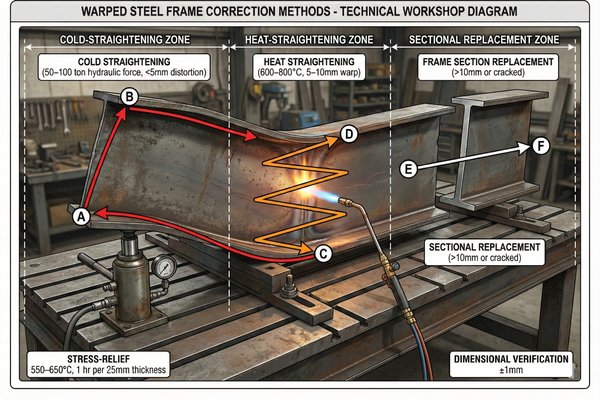
Steel frame straightening employs three corrective methods based on warping type and severity: cold straightening using hydraulic jacks (50-100 tons force) for minor distortions under 5mm on frames with yield strength reserves, heat straightening at controlled temperatures (600-800°C using oxy-acetylene torch) combined with mechanical force for moderate warping of 5-10mm, and sectional frame replacement welding for localized damage exceeding 10mm or cracked zones. The process requires frame removal, precise measurement mapping, controlled force application at calculated points (using stress distribution analysis), post-straightening heat treatment (stress relieving at 550-650°C for 1 hour per 25mm thickness), and dimensional verification (±1mm tolerance restoration). Frames with cracks at structural welds or material thinning below 70% of original thickness must be replaced per IACS Unified Requirement S21.
Cold Straightening Method: For Minor Frame Distortions
This method works for warping under 5mm where the steel hasn't exceeded its elastic limit. The frame is secured in a rigid fixture, and hydraulic pressure is applied opposite to the warping direction.
Step 1: Frame Mapping and Force Calculation
Measure warping at 100mm intervals along the affected frame member. Mark the maximum deflection point—this becomes your primary force application point. Calculate required force using beam deflection formulas: F = (3EIδ)/L³, where E is steel's elastic modulus (200 GPa), I is the frame's moment of inertia, δ is deflection, and L is the unsupported length.
For a typical 50mm×50mm×3mm angle frame with 5mm deflection over 800mm span, required force is approximately 8-12 tons.
Step 2: Fixture Setup and Force Application
Mount the frame in a straightening fixture with support points 100mm inboard from each end. Position a hydraulic jack with a spreader plate (minimum 100mm×100mm contact area) at the maximum deflection point. Apply force gradually in 1-ton increments, measuring deflection after each increment.
| Force Applied | Expected Deflection Reduction | Hold Time | Check Action |
|---|---|---|---|
| 25% calculated force | 1-1.5mm | 5 minutes | Check for frame twisting |
| 50% calculated force | 2.5-3mm | 10 minutes | Verify uniform straightening |
| 75% calculated force | 4-4.5mm | 15 minutes | Monitor for yielding signs |
| 100% calculated force | 5-6mm (slight overcompensation) | 30 minutes | Final measurement |
Release force slowly. The frame will spring back approximately 10-15%, settling at the target straightness.
Heat Straightening Method: For Moderate to Severe Warping
When cold straightening proves insufficient or the steel has been permanently deformed, controlled heating allows molecular restructuring while applying corrective force.
Step 3: Heating Zone Identification
Heat must be applied on the compression side of the warp (the concave side). For a frame bowed outward, heat the inside surface. The heating zone should be a triangular pattern: base width equal to the frame width, height 1.5-2 times the warping magnitude.
For 8mm warping, create a heating triangle 50mm wide (frame width) × 120-160mm tall.
Step 4: Controlled Heating Procedure
Use an oxy-acetylene torch with a rosebud tip, adjusted to a neutral flame. Heat the marked triangle uniformly to cherry red (approximately 700-800°C). Use temperature-indicating crayons (750°C melting point) to verify temperature.
Critical parameters:
- Heating rate: 10-15 seconds per heating cycle
- Temperature uniformity: ±50°C across the zone
- Heating cycles: 2-4 cycles with 60-second cooling intervals
- Maximum temperature: 850°C (above this, steel microstructure changes)
As you heat, the steel expands locally. Immediately apply mechanical force (hydraulic jack or come-along) in the straightening direction. The heated zone yields more easily than cold metal, allowing permanent deformation correction.
Step 5: Quenching and Stress Relief
After achieving straightness, allow the frame to air-cool naturally to below 300°C (about 10-15 minutes). Do NOT water-quench—rapid cooling creates internal stresses and potential cracking.
For frames subjected to heat straightening above 700°C, stress-relief heat treatment is mandatory:
- Reheat entire frame uniformly to 550-600°C
- Hold at temperature for 1 hour per 25mm of frame thickness (typical 3mm frame = 7-8 minutes minimum)
- Cool slowly in still air (no forced air or water)
Sectional Frame Replacement: When Localized Damage Is Severe
If warping exceeds 10mm in a localized area or cracks are present, cutting out the damaged section and welding in new material is more reliable than straightening.
Step 6: Damage Section Removal
Mark cut lines 100-150mm beyond the damaged zone on each side. Use a plasma cutter or angle grinder to remove the section, making cuts at 45-degree angles (beveled) for better weld penetration.
Step 7: Replacement Section Fabrication
Cut new frame material (same grade steel, typically A36 or AH36 for marine applications) 10mm longer than the removed section to allow fit-up adjustment. Machine both ends to 45-degree bevels matching the frame cuts.
Step 8: Welding and Post-Weld Treatment
Tack-weld the replacement section in four points (top, bottom, both sides) with the frame secured in a straight fixture. Verify alignment before final welding.
Welding parameters for 3mm frame thickness:
- Process: GMAW (MIG) with 0.9mm ER70S-6 wire
- Current: 110-130A
- Voltage: 18-21V
- Travel speed: 150-200mm/min
- Shielding gas: 75% Ar / 25% CO₂
Complete the weld in 2-3 passes, allowing each pass to cool below 150°C before starting the next. Grind weld beads flush with frame surfaces. Post-weld stress relief (550-600°C for 10 minutes) is mandatory for structural welds.
How to Replace Moisture-Damaged Fire Door Core Insulation?
Core material replacement is invasive surgery—opening the door exposes internal construction, requiring precise insulation selection, installation technique, and resealing to maintain fire rating certification.
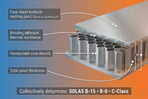
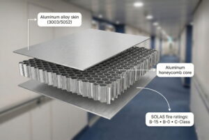
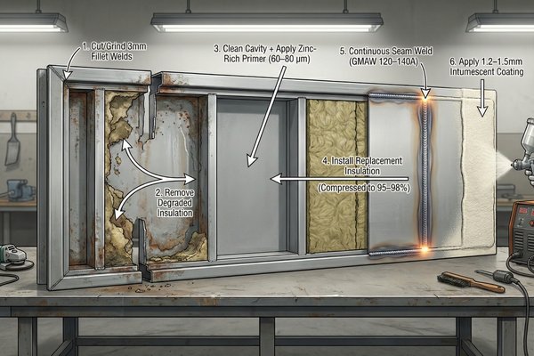
Fire door core replacement involves a six-stage process: door disassembly by cutting or grinding open edge welds (typically 3mm fillet welds along door perimeter), complete removal of degraded insulation material (rockwool, ceramic fiber, or vermiculite boards depending on original construction), cavity cleaning and rust treatment (wire brushing followed by zinc-rich primer application at 60-80 µm dry film thickness), installation of replacement insulation (density-matched material at 100-150 kg/m³ for A-60 doors, compressed to 95-98% of cavity depth), door reassembly with continuous seam welding (GMAW process at 120-140A with complete penetration), and surface finishing (grinding welds flush, applying intumescent paint at 1.2-1.5mm thickness for fire protection). Material selection must match or exceed original specifications: A-60 doors require 60mm rockwool at 120-140 kg/m³ density with 1000°C thermal resistance; A-30 doors need 40mm insulation; A-15 doors use 30mm; A-0 doors use 15mm. Replacement without classification society approval voids fire certification—always use type-approved materials listed in the door's certificate.
Door Disassembly: Accessing the Core Without Destroying the Door
Marine fire doors2 are constructed as welded assemblies—two steel sheets (typically 1.5-2mm thick) sandwiching insulation material, with edges continuously welded. Opening requires cutting these perimeter welds without damaging the door sheets.
Step 1: Preparation and Safety Setup
Remove all hardware (hinges, latches, handles, viewing glasses). Place the door horizontally on a stable work surface with adequate support. Map the weld locations—most doors have 3-4mm fillet welds along all four edges, positioned 5-10mm inward from the door edge.
Mark cutting lines with soapstone or permanent marker exactly on the weld centerline.
Step 2: Weld Removal Technique
Three methods work, each with advantages:
| Method | Tool | Speed | Edge Damage Risk | Best For |
|---|---|---|---|---|
| Angle Grinder | 4.5" grinder with 1mm cutoff wheel | Fast (30-45 min) | Moderate (burning through sheet) | Doors to be repainted |
| Plasma Cutter | 40A plasma, 1.5mm tip | Very Fast (15-20 min) | High (heat distortion) | Disposable edges |
| Grinding/Chiseling | Grinder + cold chisel | Slow (60-90 min) | Low (controlled removal) | Preservation of original edges |
I recommend the grinding/chiseling combination for quality work:
- Use an angle grinder3 to cut halfway through the weld depth
- Insert a thin cold chisel into the cut and tap gently with a hammer
- The weld separates cleanly, leaving both door sheets intact
Work systematically around the perimeter—complete one full side before moving to the next. As you approach the final corner, support the top sheet to prevent it from falling suddenly.
Step 3: Top Sheet Removal
Once all welds are cut, carefully lift the top door sheet. It may adhere to the insulation due to rust or adhesive residue. Use wooden wedges inserted at corners to gradually pry it up without bending.
Core Material Removal: Complete Cavity Cleaning
With the top sheet removed, the insulation core is exposed. The condition you'll find varies—from slightly compressed material to completely saturated, crumbling rockwool.
Step 4: Insulation Extraction
Rockwool and ceramic fiber release irritating dust particles. Work outdoors or in a ventilated area, wearing respirator (P100 rated), eye protection, and disposable coveralls.
Remove insulation in sections using gloved hands or a stiff brush. For compacted material, use a flat scraper. Place removed material directly into heavy-duty waste bags—damaged insulation cannot be reused.
For doors with framed internal construction (steel ribs welding to the bottom sheet creating compartments), clean each compartment thoroughly. Common frame configurations:
- A-60 doors (900×2000mm): Four compartments with H-pattern framing
- A-30 doors: Two compartments with single central rib
- A-0 doors: Often no internal framing
Step 5: Cavity Cleaning and Rust Treatment
After insulation removal, inspect the bottom sheet and internal frame. Moisture damage typically causes surface rust (orange scale) or deeper pitting corrosion.
Rust removal progression:
- Wire brush all surfaces to remove loose rust scale (power wire wheel at 3000 RPM for large areas)
- Sand remaining rust with 80-grit abrasive until bare metal appears
- For pitting deeper than 0.5mm, apply body filler (marine-grade epoxy filler) to restore smooth surface
- Solvent-wipe all surfaces with acetone to remove oil and dust
- Apply zinc-rich primer within 4 hours of cleaning (surface rust begins reforming immediately in humid environments)
Zinc primer specifications:
- Type: Inorganic zinc silicate (65-75% zinc content by weight)
- Application: Brush or roller (spray creates health hazards in confined spaces)
- Dry film thickness: 60-80 µm (measured with magnetic thickness gauge)
- Drying time: 24 hours at 20°C before insulation installation
Replacement Insulation Selection: Matching Fire Performance
The insulation type and density directly determine the door's fire rating. Using incorrect material creates a liability—the door may fail fire tests, voiding insurance coverage during an actual fire incident.
Step 6: Material Specification Verification
Check the door's original nameplate or classification certificate for insulation specifications. If unavailable, calculate required insulation based on the fire rating:
A-60 Doors (60-minute fire resistance):
- Material: Rockwool or ceramic fiber blanket
- Thickness: 60mm (±2mm tolerance)
- Density: 120-140 kg/m³
- Thermal conductivity: ≤0.045 W/(m·K) at 400°C
- Melting point: >1000°C
A-30 Doors (30-minute fire resistance):
- Material: Rockwool or ceramic fiber
- Thickness: 40mm
- Density: 100-120 kg/m³
- Thermal conductivity: ≤0.045 W/(m·K)
A-15 Doors (15-minute fire resistance):
- Material: Rockwool or mineral wool
- Thickness: 30mm
- Density: 80-100 kg/m³
A-0 Doors (flame containment only, no insulation requirement):
- Material: Rockwool or vermiculite board
- Thickness: 15-25mm
- Density: 60-80 kg/m³ (or vermiculite board at 400-500 kg/m³)
Step 7: Insulation Cutting and Fitting
Measure each cavity compartment precisely—width, height, and depth. Subtract 2-3mm from width and height to allow easy insertion. The depth measurement is critical: cut insulation to 102-105% of the cavity depth (you'll compress it during installation).
For a 60mm deep cavity, cut insulation at 62-63mm thickness.
Use a long serrated knife or electric carving knife for clean cuts. Rockwool compresses easily, so multiple shallow scoring passes work better than trying to cut through in one motion.
Step 8: Insulation Installation and Compression
Place cut insulation pieces into their compartments. The slight oversize requires gentle compression—this creates positive pressure that prevents settling over time.
Press each piece down evenly using a flat board spanning the compartment width. The insulation should compress to sit 1-2mm below the frame top edge. This recess allows the top door sheet to rest on the frame without insulation interfering.
For multi-compartment doors, install all sections before proceeding to reassembly. Check for gaps between insulation pieces and frame members—gaps allow heat transfer paths that reduce fire rating. Fill any gaps >5mm with loose insulation fibers, packing them firmly.
Door Reassembly: Restoring Structural Integrity
With insulation installed, the door must be welded closed using techniques that restore original strength without warping the door sheets from welding heat.
Step 9: Top Sheet Positioning and Alignment
Clean both the top sheet's underside edge and the bottom sheet's upper edge with a wire brush. Position the top sheet carefully, aligning all edges flush with the bottom sheet (±1mm tolerance).
Use magnetic clamps or C-clamps at 200mm intervals around the perimeter to hold sheets together. Place clamps 30-40mm inboard from edges to allow welding access.
Step 10: Tack Welding Sequence
Before continuous welding, tack-weld the sheets together at strategic points to prevent warping. Proper tack sequence distributes heat evenly:
- First tack: Center of one long side
- Second tack: Center of opposite long side
- Third/fourth tacks: Centers of both short sides
- Additional tacks: Midpoints between existing tacks (creating 8 tacks total)
Tack weld parameters (GMAW/MIG process):
- Wire: 0.8mm ER70S-6
- Current: 90-100A
- Voltage: 17-19V
- Tack length: 10-15mm
- Cooling time between tacks: 30-45 seconds
Step 11: Continuous Seam Welding
Start welding from one corner, working continuously around the perimeter in one direction. Use a drag technique (pushing the gun would trap slag). Maintain consistent travel speed (180-200mm/min) for uniform bead appearance.
Welding parameters for 1.5-2mm door sheets:
- Current: 110-120A
- Voltage: 18-20V
- Wire feed speed: 6-7 m/min
- Shielding gas flow: 15-18 L/min (75% Ar / 25% CO₂)
The weld creates a 3-4mm fillet joining both sheets. Overlap the weld end over the start point by 20-25mm to ensure complete sealing.
Step 12: Warpage Control During Welding
Welding heat causes local expansion. As metal cools, it contracts, potentially warping the door. Two techniques minimize warping:
Skip Welding Method:
Instead of one continuous pass, weld in 150-200mm segments, skipping around the perimeter. Complete sequence:
- Weld segment 1 (top left)
- Skip to segment 5 (bottom right)
- Weld segment 3 (top right)
- Continue in staggered pattern
This distributes heat, allowing each area to cool before adjacent areas are welded.
Backstep Technique:
Weld short 50mm segments, but progress backward. Weld from positions 200mm→150mm, then 250mm→200mm, then 300mm→250mm. This creates compressive stress opposing warping forces.
After welding, allow the door to cool naturally for at least 2 hours before removing clamps. Measure diagonal dimensions—if they differ by more than 3mm, the door has warped and requires straightening before proceeding.
How to Correct a Bowed or Bent Door Leaf Using Hydraulic Pressing?
Door leaf deformation is pure material science—applying calculated tonnage through precise contact points induces plastic deformation that counteracts existing warping, restoring flat geometry within SOLAS tolerances.
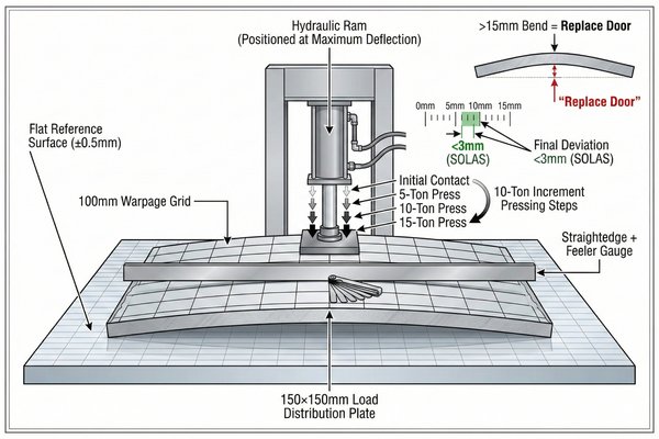
Hydraulic door straightening requires a controlled six-stage process: door positioning on a flat reference surface (precision-ground steel table or thick glass plate ensuring ±0.5mm flatness), warpage mapping using straightedge and feeler gauges at 100mm grid intervals (recording deviation magnitude and direction), press force calculation based on door thickness and material properties (typical 50-100 tons for 2mm steel sheets spanning 900mm width, using F = (4EIt)/L³ where t is deflection target), hydraulic ram positioning with load distribution plates (minimum 150mm×150mm contact area to prevent local yielding), controlled pressing in 10-ton increments with 5-minute hold intervals (allowing stress relaxation and preventing elastic spring-back), and post-pressing verification (door must achieve <3mm maximum deviation across any 1-meter span per SOLAS requirements). Doors bent beyond 15mm or showing cracking require replacement—pressing creates metallurgical stress concentrations that propagate during subsequent thermal cycling.
Press Setup: Creating the Foundation for Precision Straightening
Hydraulic pressing4 for door straightening isn't about brute force—it's precision metalworking requiring proper fixtures, calculated force vectors, and controlled application.
Step 1: Reference Surface Preparation
The door must rest on a perfectly flat surface to achieve uniform straightening. Options include:
- Precision surface plate (cast iron, Grade B, ±0.005mm/300mm flatness)—ideal but expensive
- Thick glass sheet (19mm tempered glass, 1200mm×2400mm)—cost-effective, verifiable flatness
- Steel welding table with verified flatness (measure with 2-meter straightedge, shim low spots)
Place the door with the concave side (inward bow) facing up. The convex side rests against the reference surface, creating a gap at the maximum deflection point.
Step 2: Warpage Mapping and Press Point Identification
Using a straightedge and feeler gauges, map the warpage across the entire door surface in a grid pattern (measurements every 100mm). Record the maximum deflection point—this becomes your primary press point.
For typical door warping patterns:
| Warping Pattern | Maximum Deflection Location | Press Point Strategy | Support Points |
|---|---|---|---|
| Center bow (most common) | Door center | Single ram at center | Four corners |
| Diagonal twist | Along diagonal line | Two rams at quarter points | Opposite corners |
| Edge curl | Near perimeter | Multiple rams at 300mm intervals | Center support |
| Compound (multiple bows) | Multiple peaks | Sequential pressing | Movable supports |
Step 3: Force Calculation and Equipment Selection
The required press force depends on:
- Door sheet thickness (t): 1.5-2mm typical
- Material yield strength (σ_y): 250 MPa for A36 steel
- Door width (L): 900mm typical
- Desired deflection correction (δ): Measured warpage magnitude
Using simplified beam theory for a uniformly loaded plate:
F = (4 × E × I × δ) / L³
Where:
- E = 200 GPa (steel's elastic modulus)
- I = (width × t³) / 12 (moment of inertia)
- δ = warpage to correct (in meters)
- L = unsupported span (in meters)
For a 2mm thick, 900mm wide door with 8mm center bow:
I = (0.9 × 0.002³) / 12 = 6 × 10⁻¹⁰ m⁴
F = (4 × 200×10⁹ × 6×10⁻¹⁰ × 0.008) / 0.9³
F ≈ 53,000 N ≈ 5.3 tons
However, plastic deformation requires exceeding yield strength, typically requiring 2-3× calculated force. For this door, 15-20 tons applied force is appropriate.
Pressing Procedure: Controlled Force Application
With calculations complete and equipment positioned, the actual straightening follows a methodical progression to avoid over-correction or door damage.
Step 4: Load Distribution Plate Installation
Never press directly on the door sheet with a hydraulic ram—concentrated loading creates local yielding (denting) rather than uniform straightening. Use a load distribution plate:
- Material: Steel plate, 20-25mm thick
- Size: Minimum 150mm×150mm (larger for greater warping)
- Surface: Smooth, deburred edges
- Positioning: Centered over maximum deflection point
Place the distribution plate on the door's upward-bowing surface. Position the hydraulic ram directly above it, ensuring the ram's piston contacts the plate center.
Step 5: Support Point Configuration
The door must be supported at specific points to control the straightening stress distribution. For center-bow straightening:
- Primary supports: Four points at door corners, each 50mm inboard from edges
- Support material: Hardwood blocks (50mm×50mm×25mm thick) or steel spacers
- Height adjustment: Shim supports to achieve initial contact with door surface at all four points simultaneously
The gap between door center and reference surface (where the ram will press) should be measured precisely—this is your starting deflection value.
Step 6: Incremental Pressing Sequence
Hydraulic pressing must progress in controlled steps, allowing the metal's crystalline structure to reorganize under load:
Phase 1—Initial Contact (0-5 tons):
- Slowly pump the hydraulic ram until load distribution plate contacts door firmly
- Verify all four corner supports remain in contact with door
- Hold at 5 tons for 2 minutes to assess elastic behavior
Phase 2—Plastic Deformation5 Initiation (5-15 tons):
- Increase pressure in 2-ton increments
- After each increment, hold for 3 minutes while measuring deflection reduction
- Monitor corner supports—if any lift off reference surface, redistribution of pressure is occurring correctly
- Watch for audible cracking sounds (indicating coating or paint failure, not structural damage)
Phase 3—Full Correction (15-25 tons):
- Continue increasing pressure in 2-ton increments until deflection is reduced to zero
- Typical doors require slight over-correction (pressing 1-2mm beyond flat) to compensate for elastic spring-back
- Hold at maximum pressure for 10-15 minutes to allow stress relaxation
- Monitor ram pressure gauge—pressure should remain stable (dropping pressure indicates material yielding)
Phase 4—Pressure Release:
- Reduce pressure slowly (2 tons per minute) to prevent sudden elastic rebound
- Remove ram and distribution plate
- Allow door to rest undisturbed for 30 minutes before measurement
| Press Force (tons) | Hold Time | Expected Deflection Reduction | Monitoring Action |
|---|---|---|---|
| 5 | 2 min | 10-15% (elastic only) | Verify support contact |
| 10 | 3 min | 30-40% | Check for edge lifting |
| 15 | 3 min | 50-60% | Monitor for paint cracking |
| 20 | 5 min | 75-85% | Observe pressure stability |
| 25 | 10 min | 95-100% + over-correction | Measure spring-back amount |
Step 7: Post-Pressing Measurement and Verification
After the 30-minute rest period, flip the door over and re-measure using the straightedge method. A successfully straightened door should show:
- Maximum deviation <3mm across any 1-meter span
- Uniform deviation (no new localized bows created)
- No surface cracking or visible material damage
- Diagonal measurements within 3mm of each other (indicating frame squareness)
If deflection exceeds 3mm but is less than the original warping, repeat the pressing process. If deflection is worse than original or new warping appears, the door has been over-pressed—this is difficult to correct and may require heat straightening or replacement.
Multi-Point Pressing: Correcting Complex Warping Patterns
Some doors exhibit multiple bowing areas or diagonal twisting that cannot be corrected with single-point pressing. These require sequential or simultaneous multi-point pressing.
Step 8: Diagonal Twist Correction
Diagonal twisting occurs when opposite corners are displaced in opposite directions (one corner high, opposite corner low, creating a propeller shape).
Correction requires two hydraulic rams working simultaneously:
- Position door with lowest corner down on reference surface
- Place first ram at the high corner (pressing downward)
- Place second ram under the diagonally opposite corner (pressing upward against reference surface underside)
- Apply equal pressure to both rams (10-15 tons each), increasing in 2-ton increments
- Hold at maximum pressure for 15 minutes
- Release pressure simultaneously
This technique creates opposing moments that untwist the door while maintaining overall flatness.
Step 9: Edge Curl Correction
When door edges curl upward or downward (creating a dish-shaped or dome-shaped profile), multiple pressing points along the perimeter are necessary.
For upward edge curling:
- Position door with curled edges upward
- Place distribution plates at 300mm intervals along all four edges
- Use multiple small rams (5-10 ton capacity each) or press sequentially with one ram
- Apply 8-12 tons at each point, holding for 5 minutes
- Work systematically around perimeter (not jumping between opposite sides)
The goal is to bring all edges into the same plane without creating new center bowing.
How to Reinstall and Align the Repaired Door for Proper Sealing?
Installation precision determines whether repair efforts succeed or fail—a straightened door mounted in a misaligned frame still fails fire integrity tests and regulatory inspections.
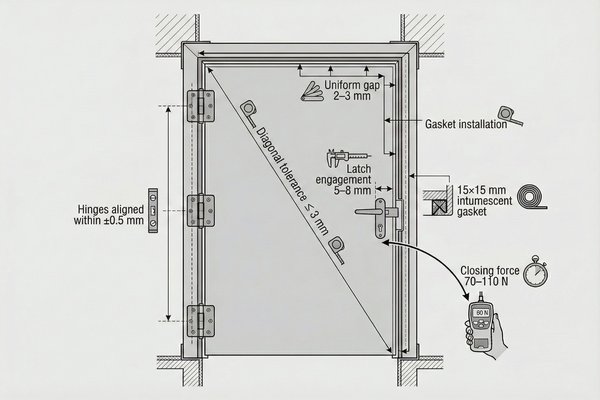
Proper fire door reinstallation follows a seven-step verification process: frame cleaning and inspection (removing all debris, rust, and old gasket material with wire brushing, confirming frame squareness within 3mm diagonal tolerance), hinge mounting with precise vertical alignment (all three hinges on the same plane within ±0.5mm using laser level or plumb bob, torquing mounting bolts to 40-50 N·m), door hanging with gap verification (2-3mm uniform cold gap around perimeter measured with feeler gauges at 12 measurement points—three per side), latch mechanism adjustment (ensuring 5-8mm latch engagement depth with compression gasket contact force of 15-25N per linear meter), gasket installation or replacement (using type-approved intumescent gaskets with 15×15mm minimum cross-section, secured with contact adhesive in continuous runs without joints), operational testing (50 opening/closing cycles checking for binding, unusual noise, or gap changes), and final certification checks (verifying nameplate presence, testing closure from both sides, measuring closing force at 70-110N per SOLAS regulation II-2/9.7). Improper installation voids all repair work—doors must pass both cold gap inspection and hot smoke tests to maintain class society approval.
Frame Preparation: Creating the Foundation for Precise Mounting
Even a perfectly straightened door fails if mounted to a damaged or misaligned frame. Frame preparation is the often-overlooked first step in successful reinstallation.
Step 1: Frame Inspection and Repair Assessment
Before touching the door, thoroughly inspect the frame:
- Structural integrity: Check for cracks at corners and hinge mounting points (use dye penetrant testing if cracks are suspected)
- Squareness: Measure both frame diagonals—difference must be <3mm
- Plumbness: Use a level on frame sides—out-of-plumb frames create binding
- Surface condition: Examine for rust, damaged gasket grooves, and paint deterioration
- Bolt hole condition: Check all hinge bolt holes for thread damage or elongation
If frame distortion exceeds 5mm or cracks are present, frame straightening or replacement is required before door installation proceeds.
Step 2: Frame Cleaning and Surface Preparation
Remove all contaminants that prevent proper sealing:
- Wire brush entire frame interior surface (power wire wheel at 2500 RPM for efficiency)
- Clean gasket grooves with a stiff nylon brush and compressed air
- Remove old gasket material remnants with a scraper and solvent wipe
- Sand rusted areas with 80-grit paper until bright metal appears
- Wipe all surfaces with acetone-dampened cloth
- Apply touch-up paint (intumescent paint matching door system) to bare metal areas
Allow paint to cure for 24 hours before proceeding with installation.
Hinge Installation: The Critical Alignment Step
Hinges are not just hardware—they're the geometric reference that determines how the door moves through its swing arc. Misaligned hinges create binding, uneven gaps, and premature wear.
Step 3: Hinge Positioning and Vertical Alignment
Marine fire doors typically use three hinges (some heavy A-60 doors use four). Standard positioning for a 2000mm tall door:
- Top hinge: 200mm from top edge
- Bottom hinge: 250mm from bottom edge
- Middle hinge: Centered between top and bottom (approximately 875mm from bottom)
The critical requirement: all three hinge barrels must be perfectly aligned on the same vertical axis (within ±0.5mm). Misalignment creates binding as the door swings.
Verification method using a plumb bob:
- Mount top hinge temporarily with two bolts (not fully tightened)
- Hang a plumb bob from top hinge barrel centerline
- Position middle and bottom hinges so their barrel centerlines align with plumb line
- Use shims behind hinges if necessary to achieve alignment
- Mark final hinge positions with a scribe
Alternative method using laser level:
- Set up a laser level projecting a vertical line along frame face
- Position each hinge so barrel centerline aligns with laser line
- This method is faster and more accurate for multiple door installations
Step 4: Hinge Mounting and Torque Specification
Each hinge typically mounts with 4 bolts (M10 or M12 size). Proper torquing prevents loosening from vibration:
| Bolt Size | Thread Type | Torque Specification | Tightening Pattern |
|---|---|---|---|
| M10 | Coarse (1.5mm pitch) | 40-45 N·m | Diagonal cross pattern |
| M12 | Coarse (1.75mm pitch) | 50-55 N·m | Diagonal cross pattern |
| M10 | Fine (1.25mm pitch) | 45-50 N·m | Diagonal cross pattern |
| M12 | Fine (1.5mm pitch) | 55-60 N·m | Diagonal cross pattern |
Use medium-strength threadlocker (Loctite 243 or equivalent) on all bolts. Tighten in stages:
- First pass: Finger-tight plus 1/4 turn on all bolts
- Second pass: 50% of final torque
- Third pass: 100% of final torque
- Verification pass: Re-check each bolt after completing all hinges
After mounting all frame-side hinge leaves, verify alignment one final time before hanging the door.
Door Hanging and Gap Adjustment
With frame hinges precisely mounted, the door can be hung and adjusted for proper clearance—a process requiring patience and repeated measurement.
Step 5: Initial Door Hanging
Door hanging requires two people for safety and control:
- Person 1: Supports door weight (50-80 kg typical for A-60 door)
- Person 2: Aligns door hinge leaves with frame hinge leaves and inserts hinge pins
Hinge pin installation sequence:
- Lift door into position, aligning bottom hinge first
- Insert bottom hinge pin partially (50% engagement)
- Align middle hinge and insert pin partially
- Align top hinge and insert pin partially
- Verify door swings freely without binding
- Fully seat all three hinge pins
- Install hinge pin retaining clips or cotter pins
Step 6: Gap Measurement and Adjustment
Close the door and measure gaps at 12 standard points using feeler gauges:
Hinge side: 3 points (150mm from top, center, 150mm from bottom)
Latch side: 3 points (same positions)
Top edge: 3 points (150mm from hinge side, center, 150mm from latch side)
Bottom edge: 3 points (same positions)
Target gaps per SOLAS requirements:
- Cold gap (door closed, no fire): 2-3mm
- Maximum variation between any two points: ±1mm
- No single gap exceeding 4mm
Gap adjustment techniques:
If hinge-side gap is too wide (>3mm):
- Shim behind frame-side hinge leaves using 0.5mm steel shims
- Add shims progressively, checking gap after each addition
- Typical correction: 0.5mm shim = 0.3mm gap reduction
If latch-side gap is too tight (<2mm):
- Check for frame out-of-squareness first (measure diagonals)
- If frame is square, adjust hinge positions outward slightly
- If frame is racked, frame correction is required
If top gap is excessive:
- Check bottom hinge for sagging or loose bolts
- Verify door isn't hanging on latch instead of hinges (common error)
- May require hinge repositioning or door trimming (last resort)
If bottom gap is too tight (door drags on threshold):
- Install taller hinge leaves or shim all hinges upward equally
- Check for floor high spots (grind down if present)
- Verify door hasn't sagged (measure from top hinge to bottom edge—should match drawing dimensions)
Latch Mechanism Adjustment and Gasket Installation
Gap adjustment ensures clearance, but the latch mechanism and compression gasket create the actual fire seal.
Step 7: Latch Engagement Verification
The latch must engage the strike plate with sufficient depth to compress the door gasket against the frame:
- Minimum engagement: 5mm (prevents accidental unlatching from vibration)
- Maximum engagement: 10mm (excessive engagement causes handle strain)
- Gasket compression: 3-5mm (achieves 15-25N/m seal force)
Latch adjustment procedure:
- Close door until latch contacts strike plate
- Measure gap between door face and frame face (should be 3-5mm)
- If gap >5mm: Move strike plate outward (shim behind plate)
- If gap <3mm: Move strike plate inward (file strike plate opening)
- Verify latch bolt fully enters strike plate opening without binding
- Test latch operation from both sides 10 times
Step 8: Intumescent Gasket Installation
Fire door gaskets serve dual purposes: smoke seal during normal operation and intumescent expansion during fire (swelling to 10-15× original volume at 200-300°C to seal gaps created by thermal expansion).
Gasket specifications for marine fire doors:
- Material: Graphite or sodium silicate based intumescent compound
- Cross-section: Minimum 15mm × 15mm (larger for A-60 doors: 20mm × 20mm)
- Expansion ratio: 10:1 to 15:1 at fire temperature
- Smoke seal performance: <3 m³/h air leakage at 25 Pa pressure
Installation technique:
- Clean gasket groove thoroughly (compressed air + solvent wipe)
- Apply contact adhesive (neoprene-based, fire-resistant) to groove bottom
- Press gasket into groove, starting at top center and working toward bottom corners
- Cut gasket to exact length at bottom corners (butt joints, not overlapped)
- Apply additional adhesive at joints
- Allow adhesive to cure 4 hours before door operation
Gasket compression verification:
- Close door fully
- Gasket should compress 20-30% (3-5mm for 15mm gasket)
- Check for uniform compression around entire perimeter by visual inspection
- Excessive compression (>40%) indicates misalignment or over-engagement
- Insufficient compression (<15%) indicates gaps that allow smoke passage
How to Conduct Post-Repair Testing and Certification?
Repairs mean nothing without verification—testing proves the door meets fire integrity standards and satisfies classification society requirements for continued operation.
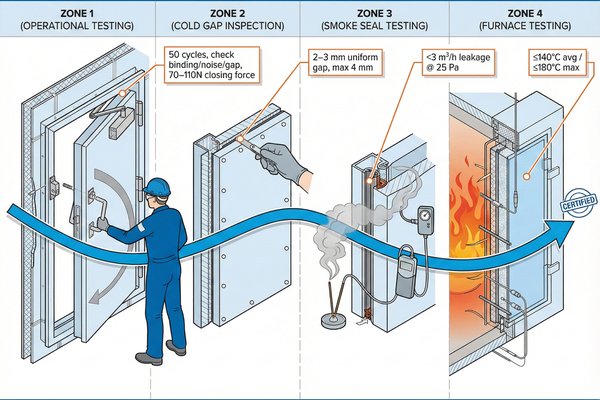
Post-repair testing requires a four-level verification protocol: operational testing (50 full-swing cycles checking for binding, unusual noise, gap changes, and latch function with door closing force measured at 70-110N per SOLAS II-2/9.7), cold gap inspection (feeler gauge measurements at 12 perimeter points confirming 2-3mm uniform gaps with maximum 4mm at any single point), smoke seal testing (incense stick test or pressure decay test showing <3 m³/h leakage at 25 Pa differential pressure per IMO Resolution A.754(18)), and hot certification where required (for doors with structural repairs or core replacement, witness testing by classification society surveyor using furnace testing to SOLAS fire curves, measuring backside temperature remaining below 140°C average / 180°C maximum above ambient for rated duration). Documentation must include repair records detailing work performed, materials used with approval certificates, test results, and surveyor sign-off for class-maintained vessels. Doors failing any test cannot return to service—they must be re-repaired or replaced to maintain vessel's Safety Management Certificate validity.
Operational Testing: Verifying Mechanical Function
Before any fire integrity testing, the door must demonstrate reliable mechanical operation—a door that binds or has malfunctioning hardware cannot maintain fire integrity during emergency evacuation.
Test 1: Swing Cycle Endurance Test
Open and close the door through its full swing arc 50 times while monitoring for:
- Binding points: Door should swing freely without resistance (except at latch engagement)
- Noise: Hinges should operate quietly (squeaking indicates misalignment or lack of lubrication)
- Gap consistency: Measure gaps every 10 cycles—variation >1mm indicates loose hinges or worn components
- Latch function: Latch should engage positively with consistent handle force (40-60N typical)
Record observations:
| Cycle Count | Gap Check Location | Gap Measurement | Observations |
|---|---|---|---|
| Initial | Latch side center | 2.5mm | Baseline measurement |
| 10 | Latch side center | 2.5mm | No change observed |
| 25 | Latch side center | 2.5mm | Slight hinge noise developing |
| 50 | Latch side center | 2.6mm | Within tolerance, noise persists |
If gap variation exceeds 1mm or binding develops during the test, stop and investigate:
- Re-check hinge bolt torque (may have loosened)
- Verify door hasn't shifted on hinges
- Inspect for interference with gasket or frame components
Test 2: Door Closing Force Measurement
SOLAS regulation II-2/9.76 requires self-closing fire doors to close with force between 70-110N measured at the latch edge. This ensures reliable closure while remaining safe for crew passage.
Measurement procedure:
- Install a spring scale or force gauge at latch edge center (1000mm from floor for 2000mm door)
- Open door to 90° position
- Release door and allow closing mechanism to operate
- Note force reading as door passes through 15° from closed position (critical measurement point)
- Repeat 5 times and calculate average
Acceptable results:
- Minimum: 70N (below this, wind or ship movement may prevent full closure)
- Maximum: 110N (above this, risk of injury to crew during emergency passage)
- Variation between tests: <10N (indicates consistent closer operation)
If force is outside range, adjust door closer:
- Too low: Increase closer spring tension or replace weakened closer
- Too high: Decrease closer tension or verify door swings freely (binding increases required force)
Cold Gap and Seal Integrity Testing
Mechanical function verified, the next step is confirming fire seal integrity through gap measurements and smoke seal testing.
Test 3: Comprehensive Cold Gap Verification
This expands the 12-point gap check performed during installation to a complete perimeter survey:
Measurement grid:
- Each edge: Measure every 200mm along perimeter (approximately 20 total measurements for standard door)
- Corners: Measure at 45° angles at all four corners (critical leak points)
- Hardware penetrations: Measure around viewing glass frames, handle penetrations
Recording template:
| Location | Target Gap | Measured Gap | Pass/Fail | Corrective Action |
|---|---|---|---|---|
| Top edge - 200mm from hinge | 2-3mm | 2.7mm | Pass | None |
| Top edge - center | 2-3mm | 2.4mm | Pass | None |
| Top edge - 200mm from latch | 2-3mm | 3.8mm | Marginal | Monitor, consider gasket adjustment |
| Latch side - 200mm from top | 2-3mm | 2.6mm | Pass | None |
| Latch side - center | 2-3mm | 2.5mm | Pass | None |
Failure criteria:
- Any single gap >4mm: Immediate failure, requires adjustment
- More than 10% of measurements >3.5mm: Marginal, requires investigation
- Average gap >3mm: Poor alignment, likely frame or door geometry issue
Test 4: Smoke Seal Testing (Incense Stick Method)
Cold gaps measure mechanical clearance, but actual air leakage depends on gasket compression and seal quality. The incense stick test provides quick qualitative verification.
Procedure:
- Close door fully and latch
- Light incense stick or smoke tube on one side of door (preferably low-pressure side if room has ventilation)
- Slowly move incense around entire door perimeter (maintain 10-15mm distance from frame)
- Observe smoke behavior at each point
Acceptable results:
- Smoke should be drawn toward door slightly but not disappear into gaps
- No visible smoke streams passing through door perimeter
- Slight smoke movement at bottom threshold acceptable (not a primary fire seal)
Failure indicators:
- Smoke visibly flowing through gap: Major leakage path present
- Smoke disappearing at specific point: Localized seal failure (missing gasket section, gasket damage, or excessive gap)
- Smoke streaming through corner joints: Corner gasket installation error
For failures, mark locations with chalk and investigate:
- Re-check gap at failure point (may exceed 4mm)
- Inspect gasket condition (compressed <15% indicates insufficient seal pressure)
- Look for gasket damage or missing sections
Test 5: Quantitative Pressure Decay Testing (Optional)
For critical applications or after major structural repairs, quantitative air leakage testing provides numerical verification. This requires specialized equipment but delivers certification-quality data.
Equipment needed:
- Blower door fan or calibrated air supply
- Differential pressure gauge (0-50 Pa range, ±0.1 Pa accuracy)
- Flow measurement device (orifice plate or rotameter)
Test setup:
- Seal all room openings except test door
- Install blower door fan in temporary frame over alternate door or ventilation opening
- Pressurize room to 25 Pa differential pressure (±2 Pa tolerance)
- Measure air flow required to maintain pressure (represents total leakage)
- Remove test door and seal opening completely
- Remeasure flow at same pressure (represents room background leakage)
- Calculate door leakage = Total flow - Background flow
Acceptance criteria per IMO Resolution A.754(18):
- Maximum door leakage: 3 m³/h at 25 Pa pressure differential
- Typical results for well-installed door: 0.5-1.5 m³/h
This test is particularly important for doors protecting high-risk spaces (engine rooms, galley boundaries) where smoke migration would be life-threatening.
Hot Testing and Classification Society Certification
For repairs involving core replacement or structural modifications, cold testing alone is insufficient—the door must demonstrate fire resistance through witness testing.
Test 6: Classification Society Witness Testing Requirements
Major repairs trigger class society involvement. Classification societies (Lloyd's Register, ABS, DNV, BV, etc.) maintain vessel certification, and they must approve repairs affecting fire safety systems.
Repairs requiring witness testing:
- Core insulation replacement (changes fire-rated assembly)
- Door leaf replacement (new component, even if to original specifications)
- Frame repairs affecting structural integrity
- Any modification changing door dimensions or fire rating
Survey process:
- Notification: Inform classification society before beginning repairs (typically 7-14 days advance notice)
- Document submission: Provide repair procedure, material certificates, and worker qualifications
- Material verification: Surveyor inspects materials prior to installation (insulation density, steel thickness, gasket specifications)
- Process witnessing: Surveyor observes critical steps (core installation, welding, gasket installation)
- Testing observation: Surveyor witnesses all cold tests and reviews results
- Certificate issuance: Surveyor issues repair certificate and updates vessel's Safety Construction Certificate
Test 7: Furnace Testing Protocol (When Required)
In some cases, classification societies require actual fire testing to a recognized standard. This occurs when:
- Door design deviates from type-approved design
- Repair uses non-approved materials
- Multiple doors of same type have failed in service (entire batch validation)
Fire test standard: IMO Resolution A.754(18) / ISO 1182 / ASTM E119 (depending on flag state)
Test procedure (simplified):
- Mount test door in furnace frame with thermocouples attached
- Expose fire side to controlled temperature curve:
- 5 minutes: 538°C
- 10 minutes: 704°C
- 30 minutes: 841°C
- 60 minutes: 945°C
- Measure unexposed side temperature continuously
- Test passes if unexposed side remains below 140°C average / 180°C maximum above ambient
- Visual inspection after test confirms no fire penetration, gasket function, and structural integrity
Test costs and logistics:
- Furnace rental: $5,000-$15,000 depending on laboratory
- Sample preparation: $2,000-$5,000
- Testing and reporting: $3,000-$8,000
- Total: $10,000-$28,000 per test
This is why using type-approved materials and following approved procedures is critical—it avoids the expense and delay of independent fire testing.
Documentation and Compliance Records
Testing is meaningless without documentation. Proper records protect the vessel owner legally and provide evidence of regulatory compliance.
Required documentation package:
- Repair work order: Details of damage found and repairs performed
- Material certificates: Type approval certificates for insulation, gaskets, paint, all showing approval by flag state administration or IACS member society
- Test results: All gap measurements, closing force tests, smoke tests with pass/fail determinations
- Photographs: Before/during/after images showing damage extent and repair quality
- Surveyor certificate: Classification society or flag state surveyor sign-off
- Updated door schedule: Revised vessel fire door inventory showing repair date and next inspection due date
Document retention:
- Keep aboard vessel in fire safety plan folder for inspection access
- Provide copies to classification society (they maintain permanent records)
- Retain for minimum 5 years after vessel scrapping (liability protection)
What Are the Cost Implications of DIY Repair vs. Professional Service?
Cost analysis must consider direct expenses, hidden costs, and risk exposure—cheap repairs that fail create far greater expenses than quality initial work.
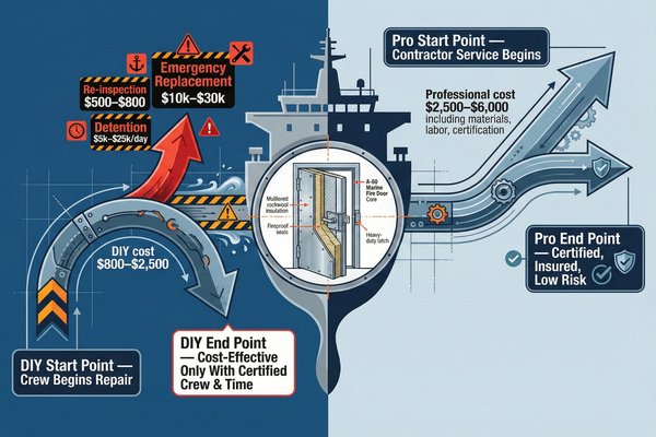
Complete cost comparison reveals that DIY marine fire door core replacement ranges from $800-$2,500 per door depending on complexity (A-60 doors requiring 60mm rockwool at $180-$220, steel work materials $150-$300, tools and equipment $300-$500 if not already owned, class surveyor attendance fees $500-$1,200), while professional marine contractor service costs $2,500-$6,000 per door including labor, materials, and certification (premium pricing reflects liability insurance, specialized equipment, and trained technicians). However, failed DIY repairs create cascading costs: re-inspection fees ($500-$800), potential detention by port state control ($5,000-$25,000 per day), insurance policy invalidation (unquantifiable risk), and emergency replacement at sea ($10,000-$30,000 due to crew accommodation costs and expedited material delivery). The break-even analysis shows DIY is cost-effective only when: vessel crew includes certified welders (avoiding $80-$120/hour labor costs), repairs involve multiple similar doors (spreading equipment investment), owner accepts class survey oversight (no attempt to bypass certification), and adequate time exists for potential rework (not under departure deadline pressure).
Direct Material Costs: What You'll Actually Spend
Understanding material costs helps budget accurately and prevents mid-project surprises when specifications require more expensive components than initially anticipated.
Material cost breakdown for A-60 door core replacement (900×2000mm typical size):
| Material Component | Specification | Quantity Needed | Unit Cost | Total Cost |
|---|---|---|---|---|
| Rockwool insulation | 60mm thick, 120 kg/m³ density | 2.2 m² (10% waste allowance) | $85-$100/m² | $187-$220 |
| Intumescent paint | 1.2mm DFT, fire-retardant | 0.5 liters | $45-$65/liter | $23-$33 |
| Intumescent gasket | 20×20mm, graphite-based | 6 meters | $18-$25/meter | $108-$150 |
| Welding wire (ER70S-6) | 0.8mm MIG wire | 1 kg spool | $12-$18/kg | $12-$18 |
| Shielding gas | 75% Ar / 25% CO₂ | 2 m³ cylinder rental + gas | $45-$75 | $45-$75 |
| Zinc primer | Inorganic, 65% zinc content | 0.25 liters | $35-$50/liter | $9-$13 |
| Contact adhesive | Neoprene-based, fire-rated | 0.25 liters | $28-$40/liter | $7-$10 |
| Grinding discs | 1mm cutoff wheels (125mm) | 5 pieces | $3-$5 each | $15-$25 |
| Sundries | Acetone, rags, wire brushes | Bulk purchase | — | $25-$40 |
| TOTAL MATERIALS | $431-$584 |
Additional costs for A-30 and A-15 doors:
- A-30 doors (40mm insulation): $320-$445 total materials (25% less insulation cost)
- A-15 doors (30mm insulation): $280-$380 total materials (35% less insulation cost)
Equipment costs (if not already owned):
| Equipment | Type/Specification | Purchase Cost | Rental Cost (per week) |
|---|---|---|---|
| MIG welder | 140A minimum capacity | $400-$800 | $75-$120 |
| Angle grinder | 4.5", 11,000 RPM | $60-$120 | $15-$30 |
| Hydraulic press | 20-50 ton capacity | $800-$2,500 (or unavailable DIY) | $200-$400 |
| Straightedge (2m) | Precision machinist's straightedge | $80-$150 | Not typically rented |
| Torque wrench | 10-100 N·m range | $40-$90 | $10-$20 |
| Feeler gauges | Metric set, 0.05-1.0mm | $15-$30 | Not typically rented |
Total equipment investment for one-time repair: $1,395-$3,690
Total equipment rental for one-time repair: $300-$570
This explains why DIY only becomes cost-effective when repairing multiple doors (spreading equipment costs) or when crew already owns welding equipment.
Labor Costs: Professional Service Pricing
Professional marine contractors price based on labor hours, material markup, overhead, and liability insurance—understanding this breakdown helps evaluate quotes.
Typical professional service pricing structure:
Labor components:
- Skilled welder/fitter: $80-$120/hour
- Helper/laborer: $40-$60/hour
- Supervisor/quality inspector: $100-$150/hour (partial time)
- Classification surveyor attendance (billed to client): $500-$1,200 per visit
Time estimates by door type:
| Door Type | Core Replacement Time | Straightening Time (if needed) | Total Labor Hours | Labor Cost Range |
|---|---|---|---|---|
| A-0 (simple, 15mm core) | 6-8 hours | 2-3 hours | 8-11 hours | $640-$1,320 |
| A-15 (30mm core) | 8-10 hours | 2-4 hours | 10-14 hours | $800-$1,680 |
| A-30 (40mm core) | 10-12 hours | 3-5 hours | 13-17 hours | $1,040-$2,040 |
| A-60 (60mm core) | 12-16 hours | 4-6 hours | 16-22 hours | $1,280-$2,640 |
Additional professional service costs:
- Material markup: 20-35% above retail cost ($525-$787 for A-60 door materials)
- Overhead and profit: 15-25% of subtotal
- Travel/mobilization (if vessel not in contractor's home port): $500-$2,000
- After-hours/weekend premium: 50-100% labor rate increase
Total professional service cost examples:
A-60 door core replacement with straightening:
- Labor (18 hours × $100/hour average): $1,800
- Materials ($508 × 1.25 markup): $635
- Overhead (20%): $487
- Surveyor attendance: $800
- Total: $3,722
A-30 door core replacement, no straightening:
- Labor (10 hours × $100/hour): $1,000
- Materials ($383 × 1.25 markup): $479
- Overhead (20%): $296
- Surveyor attendance: $800
- Total: $2,575
Emergency/expedited service (vessel under departure deadline):
- After-hours labor premium: +75% ($1,800 becomes $3,150)
- Expedited material sourcing: +$300-$800
- Rush surveyor attendance: +$400-$600
- Total A-60 emergency repair: $5,485-$6,285
This pricing explains why vessel operators prefer scheduled maintenance during yard periods rather than emergency repairs at operational ports.
Hidden Costs and Risk Factors in DIY Repairs
Direct material and labor costs represent only part of total cost—hidden expenses and failure risks often exceed visible price tags.
Hidden cost category 1: Certification and compliance
Even competent DIY repairs require classification society oversight for class-maintained vessels:
- Initial surveyor visit (pre-repair approval): $500-$800
- Material inspection visit: $400-$600 (if materials not pre-approved)
- Work completion inspection: $500-$800
- Report preparation and certificate issuance: $200-$400
- Total surveyor costs: $1,600-$2,600 (this applies to both DIY and professional repairs, but professionals often have standing agreements reducing per-visit fees)
Hidden cost category 2: Time value and opportunity cost
Crew time has value even when "free" in accounting terms:
- Chief Engineer time (planning, supervision): 8-12 hours @ $60-$90/hour effective cost = $480-$1,080
- Bosun or fitter time (actual work): 16-22 hours @ $40-$60/hour = $640-$1,320
- Total crew opportunity cost: $1,120-$2,400
This time could be spent on other maintenance, meaning deferred work accumulates elsewhere.
Hidden cost category 3: Rework and correction
First-time DIY attempts frequently require correction:
- Common issues requiring rework (based on industry data):
- Warping during welding: 35% of first attempts
- Inadequate insulation compression: 20% of installations
- Gap tolerance failures: 25% of installations
- Gasket installation errors: 15% of installations
Rework cost estimation:
- Additional materials (20% waste): $86-$117
- Additional labor (4-8 hours): $320-$960
- Additional surveyor visit: $500-$800
- Total rework cost: $906-$1,877
Risk-adjusted total DIY cost calculation:
| Cost Component | Base Cost | Probability | Expected Cost |
|---|---|---|---|
| Materials | $431-$584 | 100% | $431-$584 |
| Equipment rental | $300-$570 | 100% | $300-$570 |
| Surveyor attendance | $1,600-$2,600 | 100% | $1,600-$2,600 |
| Crew opportunity cost | $1,120-$2,400 | 100% | $1,120-$2,400 |
| Rework costs | $906-$1,877 | 30% | $272-$563 |
| TOTAL EXPECTED COST | $3,723-$6,717 |
This risk-adjusted DIY cost ($3,723-$6,717) closely matches or exceeds professional service cost ($2,575-$3,722), explaining why professional service often delivers better value despite higher headline pricing.
Catastrophic Failure Costs: What Happens When Repairs Don't Meet Standards
Beyond rework, inadequate repairs create regulatory and commercial risks with devastating financial consequences.
Failure scenario 1: Port State Control detention
If port state inspectors discover non-compliant fire doors during routine inspection:
- Vessel detention: Prohibited from sailing until deficiencies corrected
- Detention costs:
- Vessel operating cost: $5,000-$25,000 per day (depending on vessel size)
- Crew accommodation extension: $1,000-$3,000
- Cargo delay penalties: $10,000-$100,000+ (contract-dependent)
- Emergency contractor mobilization: Premium pricing (+50-100%)
- Lost charter revenue: $20,000-$150,000 per day for commercial vessels
Example detention cost (3-day delay to repair 4 doors):
- Vessel operating cost (3 days × $15,000): $45,000
- Emergency repairs (4 doors × $5,500): $22,000
- Cargo delay penalty: $35,000
- Lost charter income (3 days × $80,000): $240,000
- Total detention cost: $342,000
This single incident costs 57-137× more than proper initial professional repair ($2,500-$6,000 per door × 4 doors = $10,000-$24,000).
Failure scenario 2: Insurance policy invalidation
Marine insurance policies contain clauses requiring compliance with classification society requirements. Non-compliant repairs can void coverage:
Policy clause example (Lloyd's standard wording):
"This insurance shall not cover any loss, damage, or liability arising from the vessel being operated with class or statutory certificates suspended, withdrawn, or obtained through fraudulent misrepresentation of vessel condition..."
Consequences of invalidated coverage:
- Fire loss not covered (potential $5M-$500M depending on vessel value)
- Liability claims not covered (pollution, injury, cargo damage)
- Hull and machinery claims rejected
- Retrospective premium recovery by insurer
Real case example: A coastal ferry operated with uncertified fire door repairs. A subsequent engine room fire caused $12 million in damage. The insurer denied the claim after investigation revealed the non-compliant doors, forcing the owner into bankruptcy.
Failure scenario 3: Total loss in actual fire
The ultimate cost of failed fire protection is loss of life and vessel:
Statistical data from IMO fire casualty database (2010-2020):
- Engine room fires account for 42% of vessel fire incidents
- Proper fire door closure reduces fire spread probability by 89%
- Failed fire doors contribute to 23% of fire-related total losses
- Average total loss value: $25M-$350M depending on vessel type
A $3,000 DIY repair that fails during a fire creates unlimited liability—no cost comparison can capture this risk magnitude.
Break-Even Analysis: When Does DIY Make Financial Sense?
Despite risks, DIY repairs can deliver value in specific scenarios. Break-even analysis identifies when DIY transitions from risky economy to sensible strategy.
Break-even condition 1: Multiple door repairs spreading fixed costs
Equipment investment ($1,395-$3,690) becomes economical when repairing multiple doors:
| Number of Doors | DIY Total Cost | Professional Total Cost | DIY Savings | Payback |
|---|---|---|---|---|
| 1 door | $3,723-$6,717 | $2,575-$3,722 | -$1,148 to -$2,995 | Negative |
| 2 doors | $4,585-$7,885 | $5,150-$7,444 | -$859 to +$565 | Marginal |
| 3 doors | $5,447-$9,053 | $7,725-$11,166 | +$672 to +$2,113 | Positive |
| 4 doors | $6,309-$10,221 | $10,300-$14,888 | +$3,991 to +$4,667 | Strong positive |
Conclusion: DIY becomes cost-effective at 3+ doors, assuming successful completion without major rework.
Break-even condition 2: Existing crew qualifications and equipment
Vessels with certified welders and owned equipment eliminate major cost barriers:
Cost comparison with existing resources:
- Materials only: $431-$584 per door
- Surveyor attendance (unavoidable): $1,600-$2,600 (spread across multiple doors)
- Crew opportunity cost: $1,120-$2,400 (but crew already employed)
Effective DIY cost with existing resources (3 doors):
- Materials (3 × $508 average): $1,524
- Surveyor attendance: $2,100
- Total: $3,624 for 3 doors = $1,208 per door
Professional cost: $2,575-$3,722 per door
Savings: $1,367-$2,514 per door (53-68% cost reduction)
This scenario strongly favors DIY for vessels with qualified crew.
Break-even condition 3: Non-critical timing without departure pressure
DIY requires time for learning, errors, and rework. Cost-effectiveness depends on schedule flexibility:
Scenario A: Vessel in extended yard period (2-4 weeks available)
- Adequate time for careful work and rework if needed
- Surveyor scheduling flexible
- No commercial pressure
- DIY risk: LOW
Scenario B: Vessel operational with tight port schedule (24-48 hours)
- Insufficient time for rework
- Surveyor availability uncertain
- Departure delay creates massive costs ($5,000-$25,000/day)
- DIY risk: EXTREME
Cost-benefit formula:
DIY makes sense when: (Professional Cost - DIY Cost) > (Delay Probability × Detention Cost per Day × Expected Delay Days)
Example calculation:
- Professional cost advantage: $2,575 - $1,208 = $1,367 savings per door
- Delay probability (DIY first attempt): 30%
- Detention cost: $15,000/day
- Expected delay: 2 days
- Risk cost: 0.30 × $15,000 × 2 = $9,000
Conclusion: $1,367 savings < $9,000 risk exposure = Professional service is correct choice
Strategic Decision Matrix: DIY vs. Professional Service
Comprehensive decision tool integrating all cost and risk factors:
| Decision Factor | Favor DIY | Favor Professional |
|---|---|---|
| Number of doors | 3+ doors | 1-2 doors |
| Crew qualifications | Certified welders onboard | No qualified welders |
| Equipment availability | Owned welding equipment | Must rent equipment |
| Time availability | Extended yard period (weeks) | Operational port (days) |
| Door complexity | A-0 or A-15 (thin insulation) | A-60 (thick insulation, high warping risk) |
| Straightening required | No warping present | Severe warping (>10mm) |
| Surveyor relationship | Established relationship, flexible scheduling | First-time interaction, uncertain availability |
| Risk tolerance | Owner-operated vessel, self-insured | Commercial operator, strict insurance requirements |
| Previous experience | Crew has performed similar repairs | First attempt at fire door repair |
Scoring system (assign +1 for each "Favor DIY" factor present):
- Score 7-9: DIY strongly recommended
- Score 5-6: DIY acceptable with careful planning
- Score 3-4: Marginal, consider professional service
- Score 0-2: Professional service strongly recommended
This systematic approach prevents emotional decision-making based solely on headline cost numbers.
Conclusion
Marine fire door core replacement and warping correction require systematic attention to material specifications, precise welding technique, controlled heat management, hydraulic straightening procedures, and rigorous testing protocols—success depends not on specialized skills, but on methodical execution of proven procedures. Fire integrity systems protect lives and assets worth millions—investing in quality repairs, whether DIY or professional, remains the only rational choice when measured against catastrophic failure consequences.
-
Understanding thermal expansion is crucial for managing material integrity under temperature changes, especially in marine environments. ↩
-
Explore this link to understand the unique construction and safety features of Marine fire doors. ↩
-
Discover expert tips on using an angle grinder effectively for weld removal. ↩
-
Explore the fundamentals of hydraulic pressing to understand its role in precision metalworking. ↩
-
Understand the concept of plastic deformation and its relevance in metal straightening. ↩
-
Familiarize yourself with SOLAS regulations to ensure compliance and safety in maritime environments. ↩