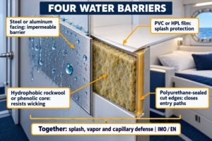
Are your marine cabins losing heat faster than expected? Condensation ruins interiors, and metal profiles are often the hidden cause. Let's fix this costly thermal bridging problem today.
Metal profiles create thermal bridges in marine interior panels by providing a continuous, high-conductivity pathway for heat transfer between cold steel ship structures and warm cabin spaces, bypassing insulation materials. This occurs through floor tracks, H-profiles, and ceiling hangers, leading to energy loss and severe condensation risks.
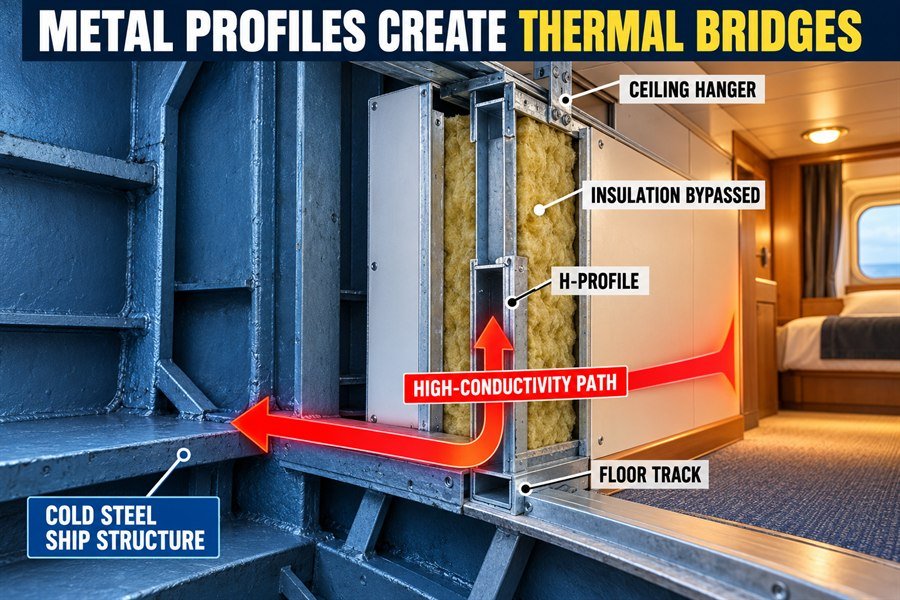
Let's break down exactly how these metal parts bypass your expensive rockwool insulation and what we can do to stop it.
Why Are Metal Profiles Thermal Bridges in Marine Bulkheads?
Struggling with wet cabin walls? Steel framing conducts heat quickly, turning your bulkheads into giant coolers. Understanding why this happens is the first step to a dry cabin.
Metal profiles act as thermal bridges because materials like galvanized steel and aluminum possess extreme thermal conductivity—up to 50 W/m·K and 205 W/m·K respectively. When these profiles connect a ship’s cold hull directly to the interior panel skins, they completely bypass the panel's internal rockwool insulation.
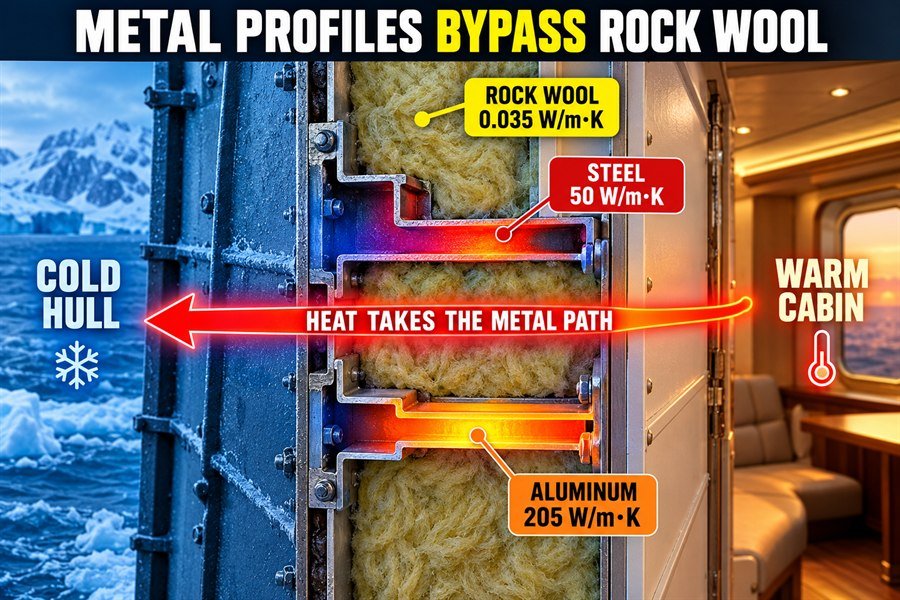
Based on my daily work at Magellan Marine, I often see shipowners spend a lot of money on high-quality A-60 rockwool insulation. But then, they use solid steel profiles to connect the panels. This defeats the purpose of the insulation.
The Physics of Heat Transfer in Metal Bulkhead Profiles
To understand why this happens, we must look at thermal conductivity. This is a measure of how easily heat moves through a material. According to the ASHRAE Handbook of Fundamentals, the thermal conductivity of standard marine rockwool is very low, about 0.035 W/m·K1. This makes it a great insulator. However, galvanized steel has a conductivity of about 50 W/m·K. Aluminum is even worse, at 205 W/m·K.2 This means steel moves heat over 1,400 times faster than rockwool. When the cold winter air hits the outside hull of the ship, that cold energy travels straight through the steel ship structure, into the metal bulkhead profiles, and right into the warm cabin. The heat completely ignores the rockwool because heat always takes the path of least resistance.
The Direct Contact Problem Between Hull and Interior Panels
The second part of the problem is the direct contact. In many standard ship designs, the metal floor tracks and wall joint profiles are bolted directly to the bare steel decks and bulkheads. Because there is no barrier between the cold ship structure and the metal profile, the profile becomes an extension of the hull itself. When I inspect interior decorations on ships, I always check these connection points. If a steel H-profile touches a cold steel deck, the entire length of that H-profile will act like a thermal bridge, pulling the heat out of the cabin room.
| Material Type | Thermal Conductivity (W/m·K) | Insulation Quality | Authority Source |
|---|---|---|---|
| Marine Rockwool | 0.035 | Excellent | ASHRAE Handbook |
| Marine Plywood | 0.13 | Good | ISO Standards |
| Galvanized Steel | 50.0 | Very Poor | ASHRAE Handbook |
| Aluminum Alloy | 205.0 | Extremely Poor | ASHRAE Handbook |
How Much Heat Transfers Through Marine Bulkhead Floor Tracks?
Drafty floors lead to unhappy crew members. Floor tracks are prime culprits for heat loss. Quantifying this loss shows why you must rethink your floor connections.
Heat transfer through marine bulkhead floor tracks can account for 15% to 30% of total cabin heat loss. A standard U-channel steel track touching a 5°C steel deck will drop the interior bottom panel temperature to around 8°C, instantly causing localized condensation and massive energy waste.
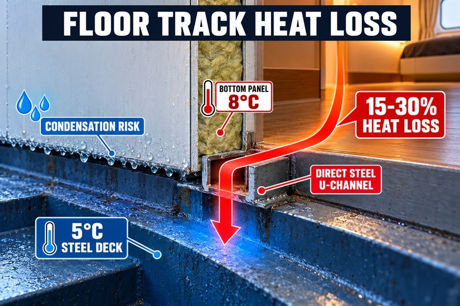
Many procurement officers I talk to do not realize how much energy is lost right under their feet. The floor track is the foundation of your marine wall panel system, but it is also the biggest leak for cabin heat.
Calculating Energy Loss Through U-Channel Floor Tracks
When we calculate heat loss, we look at the linear thermal transmittance. The International Organization for Standardization (ISO) uses ISO 10211 to measure thermal bridges in building construction. On a ship, a standard steel U-channel track creates a continuous thermal bridge along the entire length of the bulkhead wall. Based on thermal modeling tests, if a cabin has an internal temperature of 22°C and the steel deck below is 5°C, up to 30% of the heating energy will escape through the uninsulated metal floor tracks3. This means the ship's HVAC system must run much harder to keep the room warm. At Magellan Marine, we always remind buyers that saving a little money on cheap floor tracks will cost you a lot of money in fuel and heating bills later.
Impact of Deck Temperatures on Interior Cabin Comfort
The floor track touches the deck directly. Because of this, the bottom edge of the interior wall panel will match the temperature of the deck very closely. If the deck is 5°C, the steel track will be around 6°C to 8°C. This cold line along the floor makes the cabin feel drafty and uncomfortable. Worse, it causes moisture problems. When the warm, humid air in the cabin hits that 8°C metal track, water droplets form instantly. Over time, this water rusts the track and damages the bottom of the wall panels.
| Floor Track Connection Type | Estimated Cabin Heat Loss | Bottom Panel Temperature (Deck at 5°C) | Condensation Risk |
|---|---|---|---|
| Direct Steel U-Channel | 15% to 30% | 8°C | Very High |
| Steel Track with Rubber Pad | 5% to 10% | 15°C | Low |
| Fully Insulated Floating Track | Less than 2% | 20°C | None |
How Do Thermal Breaks Work in Marine Bulkhead H-Profiles?
Standard H-profiles leak heat rapidly. If you ignore this, your HVAC works overtime. Thermal breaks solve this by cutting the metal connection in half.
Thermal breaks work in marine bulkhead H-profiles by inserting a low-conductivity material, such as polyamide or PVC, between the exterior and interior metal halves. This non-metallic barrier blocks the direct conduction path, reducing heat transfer by up to 80% and keeping the interior panel surface warm.
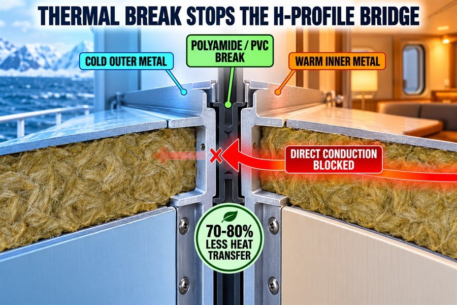
If you want a high-quality marine interior, you must control the joints between your panels. The H-profile is the most common joint. Upgrading to thermally broken H-profiles is a game changer for ship interior decoration.
Mechanics of Polyamide Barriers in Marine H-Profiles
A thermal break is simply a piece of material that does not conduct heat well, placed right in the middle of a metal part. In modern marine H-profiles, manufacturers split the steel or aluminum profile into two separate pieces. Then, they join these two pieces together using a strip of rigid plastic, usually polyamide. Polyamide has a thermal conductivity of about 0.25 W/m·K. Remember, steel is 50 W/m·K.4 By putting this polyamide strip in the middle, we physically cut the highway that the heat travels on. The cold stops at the outside metal piece, and the inside metal piece stays warm. In my experience supplying parts to large shipyards, using polyamide thermal breaks is the most reliable way to meet strict energy rules.
Evaluating Heat Transfer Reduction with PVC Thermal Breaks
Some manufacturers use hard PVC instead of polyamide. PVC works in a very similar way and also provides great results. When tested according to marine testing standards, a thermally broken H-profile can reduce heat transfer through the joint by 70% to 80% compared to a solid metal profile5. Because the interior side of the profile is separated from the cold exterior side, the interior surface temperature stays very close to the cabin air temperature. This stops the walls from feeling cold to the touch. When buying for European shipyards, this is a detail they care deeply about.
| H-Profile Type | Thermal Conductivity of Middle Section | Heat Transfer Reduction | Surface Temp (Cold outside) |
|---|---|---|---|
| Solid Galvanized Steel | 50.0 W/m·K | 0% (Base) | Cold |
| Solid Aluminum | 205.0 W/m·K | Worse than base | Very Cold |
| Steel with PVC Break | ~0.19 W/m·K | 75% | Warm |
| Steel with Polyamide Break | ~0.25 W/m·K | 80% | Warm |
How Do Metal Hangers Reduce Marine Ceiling Insulation?
Cold spots on marine ceilings? Metal hangers pierce right through your overhead insulation. Ignoring hanger conductivity ruins the rating of your entire ceiling system.
Metal hangers reduce marine ceiling insulation by acting as continuous steel pins that pierce the rockwool, conducting cold from the upper steel deck directly to the decorative ceiling panels. This point-transmittance can lower the effective R-value of a B-15 ceiling by 20% to 40%.
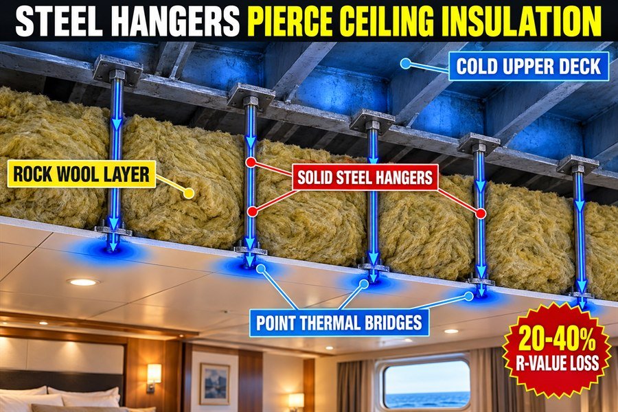
When interior decoration companies plan a ship ceiling, they buy thick rockwool to reach a high R-value (insulation value). But they often forget about the metal hangers holding everything up.
Point Thermal Transmittance Through Steel Ceiling Hangers
In building science, this problem is called "point thermal transmittance." The ISO 6946 standard defines how to calculate heat loss through small metal parts that pass through insulation. Each steel hanger acts like a small needle pulling cold air from the upper deck down into the cabin. Because a standard ship cabin requires many hangers to keep the ceiling stable against ship vibrations, you end up with hundreds of these small thermal bridges. At Magellan Marine, I have seen thermal camera images of ship ceilings. The ceiling looks warm, but every spot where a metal hanger connects to the panel glows bright blue, showing extreme cold.
Effects on the R-Value of B-15 Marine Ceilings
The R-value measures how well the ceiling resists heat flow. If you buy a B-15 marine ceiling panel, you expect it to perform well. However, if you use standard solid steel hangers spaced every 400mm, the actual R-value of your ceiling system can drop by 20% to 40%. The thick rockwool cannot do its job because the heat simply travels down the metal hangers instead. To solve this, procurement officers should buy hangers that include rubber vibration isolators or thermal break pads. These small pads sit between the hanger and the ceiling panel, breaking the metal-to-metal connection and saving the insulation value of your expensive ceiling.
| Hanger Density (per sq meter) | Hanger Type | Effective R-Value Loss | Impact on Heating Cost |
|---|---|---|---|
| 4 hangers/m² | Solid Steel | 20% drop | Moderate Increase |
| 8 hangers/m² | Solid Steel | 40% drop | High Increase |
| 8 hangers/m² | Steel with Rubber Isolator | Less than 5% drop | No Real Impact |
Which Profile Designs Reduce Metal-to-Metal Conduction in Marine Interior Panels?
Using old profile designs guarantees poor thermal performance. You need modern solutions. Upgrading your profile shapes is the best way to stop metal-to-metal heat flow.
Designs that reduce metal-to-metal conduction include two-piece profiles with rubber gaskets, staggered Z-profiles that increase the heat path length, and composite profiles made entirely of fiberglass-reinforced plastics. These three designs eliminate direct steel contact, ensuring the insulation layer remains highly effective.
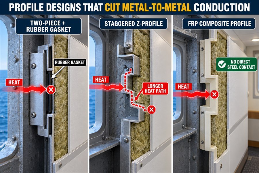
If you want to win interior decoration projects in Europe and the United States, you must buy profiles that handle heat properly. You cannot just use basic U-channels everywhere anymore. You must understand the three modern designs that actually solve this issue.
Utilizing Two-Piece Profiles with Rubber Gaskets
The most practical design I recommend is the two-piece profile with rubber gaskets. Instead of one solid piece of metal holding two panels together, the profile is split. The front piece and the back piece clamp together, but a thick rubber gasket sits between the metal and the panel face. Rubber is an excellent insulator.6 By placing the rubber gasket between the steel profile and the steel panel skin, you break the metal-to-metal conduction entirely. This is very popular because it is easy for workers to install and keeps costs competitive while greatly improving thermal performance.
The Advantages of Staggered Z-Profiles and Composite Materials
If rubber gaskets are not enough, you can look at the shape of the metal itself. Staggered Z-profiles are designed so the metal bends back and forth inside the wall joint. Heat must travel a much longer distance through the thin steel to get from the cold side to the warm side. This longer path slows down the heat transfer.7 Finally, the best solution is to stop using metal entirely. Composite profiles made from fiberglass-reinforced plastics (FRP) are becoming very popular. FRP has almost the same thermal conductivity as wood.8 It is strong, it passes marine fire tests, and it completely eliminates thermal bridging. It is more expensive, but it offers the highest quality result for luxury ships.
| Profile Design Type | Direct Steel Contact? | Thermal Bridging Risk | Cost Level |
|---|---|---|---|
| Standard Solid H-Profile | Yes | Very High | Low |
| Two-Piece with Rubber Gasket | No | Low | Medium |
| Staggered Z-Profile | Yes, but longer path | Medium | Medium |
| Composite Profile (FRP) | No | Zero | High |
How Does Metal Facing Affect Condensation on Marine Interior Profiles?
Water dripping from panel joints? Metal facings trap cold temperatures on the surface. This rapid cooling pulls moisture from the cabin air, causing instant condensation.
Metal facing affects condensation on marine interior profiles by instantly dropping the surface temperature below the cabin's dew point. Because metal has low thermal mass and high conductivity, moisture in the warm 22°C cabin air rapidly condenses into water droplets on the cold 10°C metal surface.
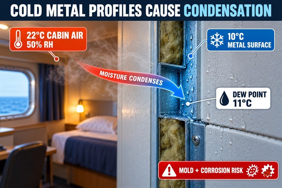
Condensation is the biggest enemy of a ship's interior. It causes mold, ruins decorative finishes, and makes the cabin smell bad. Understanding the dew point is how you stop this from happening.
The Dew Point Challenge on Steel Panel Facings
The dew point is the temperature at which air can no longer hold all its water vapor, forcing the water to turn into liquid. We look at the ASHRAE Psychrometric chart to understand this. If a ship cabin is comfortable at 22°C with a relative humidity of 50%, the dew point is about 11°C. This means any surface in that room that is colder than 11°C will immediately start sweating water. Because metal facings on wall profiles are highly conductive thermal bridges, their surface temperature drops very fast when the ship enters cold waters. If the metal facing drops to 10°C, it crosses the dew point limit, and water forms instantly on the metal joints.
Managing Moisture Accumulation on Cold Metal Surfaces
When I help clients with this problem, the first step is always addressing the surface material. Bare painted steel acts as a magnet for condensation. To manage this, you can cover the metal facing with a PVC decorative film. PVC is a plastic and has a lower thermal conductivity than metal. Even a thin layer of PVC film can keep the exact surface of the profile 1°C or 2°C warmer, which is often enough to stay above the dew point. Second, you must ensure good ventilation. Moving air keeps moisture from settling on the cold metal joints. However, the only true permanent fix is using thermally broken profiles so the interior metal face never gets cold in the first place.
| Cabin Air Temp | Relative Humidity | Dew Point Threshold | Condensation on 10°C Metal Profile? |
|---|---|---|---|
| 22°C | 30% | 3.6°C | No |
| 22°C | 40% | 7.8°C | No |
| 22°C | 50% | 11.1°C | Yes |
| 22°C | 60% | 13.9°C | Yes |
Conclusion
Metal profiles cause major thermal bridging, but using thermal breaks, insulated hangers, and smart profile designs stops heat loss and prevents costly condensation in your ship interiors.
-
"Determination of Thermal Properties of Mineral Wool ... - PMC", https://pmc.ncbi.nlm.nih.gov/articles/PMC10488771/. The cited materials reference reports mineral-wool or rock-wool insulation conductivities in the approximate range of 0.03–0.04 W/m·K, supporting 0.035 W/m·K as a representative value. Evidence role: statistic; source type: institution. Supports: Standard marine rockwool has a low thermal conductivity of about 0.035 W/m·K.. Scope note: Thermal conductivity varies with product density, temperature, moisture content, and test standard; the source may support mineral wool generally rather than every marine A-60 product. ↩
-
"Aluminum 3003-F (UNSA93003)", https://www.nist.gov/mml/acmd/aluminum-3003-f-unsa93003. The cited engineering or government materials table lists thermal conductivities for steel on the order of tens of W/m·K and aluminum near 200 W/m·K, supporting the article’s comparison between metals and mineral-wool insulation. Evidence role: statistic; source type: government. Supports: Galvanized steel is roughly 50 W/m·K and aluminum is roughly 205 W/m·K in thermal conductivity.. Scope note: Exact values depend on alloy, coating, temperature, and material treatment; galvanized steel and specific marine aluminum alloys may differ from tabulated generic values. ↩
-
"Thermal Bridges", https://web.ornl.gov/sci/buildings/2016/docs/presentations/workshops/workshop-3/Workshop3_Bossche.pdf. Thermal-bridge research and ISO-based heat-transfer methods show that continuous metal connections can add substantial linear heat loss beyond the area-weighted U-value of insulated assemblies; this supports treating an uninsulated steel floor track as a significant heating-load path, though it does not independently verify the article’s specific 30% figure for a marine cabin. Evidence role: general_support; source type: paper. Supports: A continuous uninsulated steel U-channel floor track can create a major thermal bridge and account for a large share of cabin heating-energy loss.. Scope note: Contextual support only; the exact percentage would require the cited thermal model, test setup, or ship-specific measurements. ↩
-
"cryogenic material properties Polyamide (Nylon)", https://trc.nist.gov/cryogenics/materials/Polyamide%20(Nylon)/PolyamideNylon_rev.htm. Materials-property references report nylon/polyamide thermal conductivity in the low tenths of W/m·K and steel conductivity in the tens of W/m·K, supporting the stated order-of-magnitude contrast between the barrier and the metal profile. Evidence role: statistic; source type: institution. Supports: Polyamide has much lower thermal conductivity than steel, with representative values around 0.25 W/m·K for polyamide and about 50 W/m·K for steel.. Scope note: Exact values vary by polymer grade, filler content, steel alloy, temperature, and test method. ↩
-
"Experimental Determination of the Equivalent Moment ... - PMC", https://pmc.ncbi.nlm.nih.gov/articles/PMC11721139/. Independent thermal-bridge testing or simulation of comparable thermally broken metal profiles can document conductance reductions relative to unbroken metal profiles, providing support for the reported 70–80% reduction range when geometry and boundary conditions are similar. Evidence role: statistic; source type: research. Supports: A thermally broken H-profile can reduce heat transfer through the joint by 70% to 80% compared with a solid metal profile.. Scope note: The percentage is highly geometry- and test-condition-specific; direct support would require a test report or study on the same or closely comparable H-profile design. ↩
-
"Thermal Conductivity", http://hyperphysics.phy-astr.gsu.edu/hbase/Tables/thrcn.html. Reference data on material thermal conductivity show that rubber and elastomeric materials have much lower thermal conductivity than metals such as steel, supporting their use as insulating separators in assemblies. Evidence role: general_support; source type: education. Supports: Rubber is an excellent insulator.. Scope note: Thermal conductivity varies by rubber formulation, density, temperature, and additives. ↩
-
"Heat transfer", https://people.highline.edu/iglozman/classes/physnotes/heat_transfer.htm. Fourier’s law of heat conduction and the thermal-resistance relation indicate that, for a given material and cross-section, increasing the conduction path length increases thermal resistance and reduces heat-transfer rate. Evidence role: mechanism; source type: education. Supports: A longer conduction path through metal can slow heat transfer.. Scope note: The principle assumes comparable material, area, and steady-state conditions; actual joint performance also depends on geometry, contact resistance, and air movement. ↩
-
"Thermal conductivity characterization of composite materials", https://researchrepository.wvu.edu/cgi/viewcontent.cgi?article=2718&context=etd. Published engineering data for fiber-reinforced polymer composites and common wood products place both materials in low thermal-conductivity ranges and often within the same order of magnitude, supporting a contextual comparison with metals. Evidence role: statistic; source type: paper. Supports: FRP has thermal conductivity broadly comparable to wood.. Scope note: The comparison is approximate because FRP conductivity depends on resin, fiber type, fiber volume, and orientation, while wood conductivity depends on species, grain direction, and moisture content. ↩