
You buy marine panels from Asia to save money, but they do not fit the ship. Installation delays cost you money and ruin your shipyard timeline. Let us stop these costly fit issues before they start.
Avoiding fit issues requires a five-step approach: compensating for hull deflection, reusing existing grids, adapting to steel bulkhead tolerances, matching panel thicknesses, and utilizing 3D laser scanning. Managing these factors ensures your panels meet strict shipyard standards while controlling lead times and reducing on-site material waste.
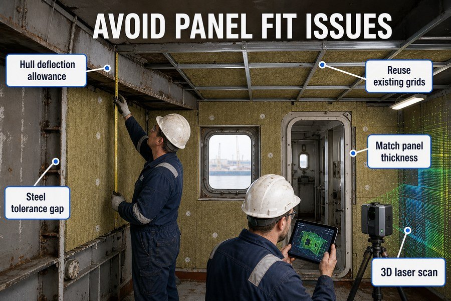
I remember a project where a client bought beautiful wall panels from a Chinese factory. They shipped them to a European shipyard, but the panels left huge gaps during installation. The client blamed the factory. But the real issue was the actual condition of the old ship. Old ships are never perfectly straight. Let me show you how to fix these fit issues on your next project.
How Does Hull Deflection Cause Fit Issues for Retrofitted Marine Wall Panels?
Steel ships bend over time. When you install straight wall panels on a curved hull, gaps appear quickly. This forces your installation team to waste days cutting panels on site.
Hull deflection causes three fit issues: vertical misalignment up to 15mm, horizontal panel buckling under load, and gap formation at deck joints. Ships bend over decades of service, changing the original deck-to-deck height and forcing rigid retrofitted panels out of their intended structural plumb lines.
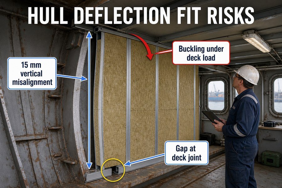
Vertical Misalignment and Horizontal Buckling from Hull Deflection
I see this problem often when supplying panels for old vessels. A steel ship is not a rigid box. It moves and bends over years at sea. The International Association of Classification Societies (IACS) standard states a typical hull can deflect up to L/1000, where L is the length of the ship. On a 200-meter ship, this means major structural movement. This movement changes the deck-to-deck height. When you install a perfectly straight marine wall panel, you face vertical misalignment. The deck height might be 2100mm near the cabin door, but 2115mm near the center of the room. This 15mm vertical misalignment means standard panels will not reach the top track.
Also, hull deflection causes horizontal panel buckling. When a ship loads heavy cargo, the steel deck bends downward. If you fix the wall panels tightly between the top and bottom decks without any clearance, the deck weight pushes down on the panels. Standard 50mm rockwool core panels can only handle a specific amount of pressure. If the deck pushes down, the panels will buckle or bend horizontally1. The panel joints will pop open. You will fail the visual inspection.
Managing Gap Formation at Deck Joints
The third issue is gap formation at deck joints. When the hull twists, the floor does not stay flat. You install a flat U-profile bottom track. Because the deck has a curve, gaps form under the track. Sound and fire can pass through these gaps. SOLAS Chapter II-2 requires tight fire boundaries. You cannot leave a 10mm gap under an A-60 wall panel track.
To fix these three issues, we must use sliding top tracks. A deep top profile of 50mm allows the panel to float. If the deck moves 15mm, the panel slides inside the top track. It does not buckle, and it does not leave gaps. I always tell my clients to specify sliding top tracks when ordering from factories in China.
| Hull Deflection Issue | Measurement Impact | Solution |
|---|---|---|
| Vertical Misalignment | Up to 15mm height variance | Use 50mm deep U-profile sliding top tracks |
| Horizontal Buckling | Panels bend outwards under pressure | Leave a 15mm expansion gap at the top |
| Gap Formation | 5mm to 10mm gaps under bottom tracks | Apply approved marine fire sealant under tracks |
How Does Reusing Existing Suspension Grids Prevent Gaps in Marine Ceiling Panel Retrofits?
Ripping out old ceiling grids takes too long. If you build a new grid, the old pipes get in the way. Reusing the old suspension grid saves time and stops annoying gaps.
Reusing existing suspension grids prevents gaps through two mechanisms: preserving established leveling baselines and maintaining original integration with HVAC and piping clashes. This method avoids the 5mm to 10mm tolerance shifts that occur when installing new carrier systems onto aged deckhead structures.
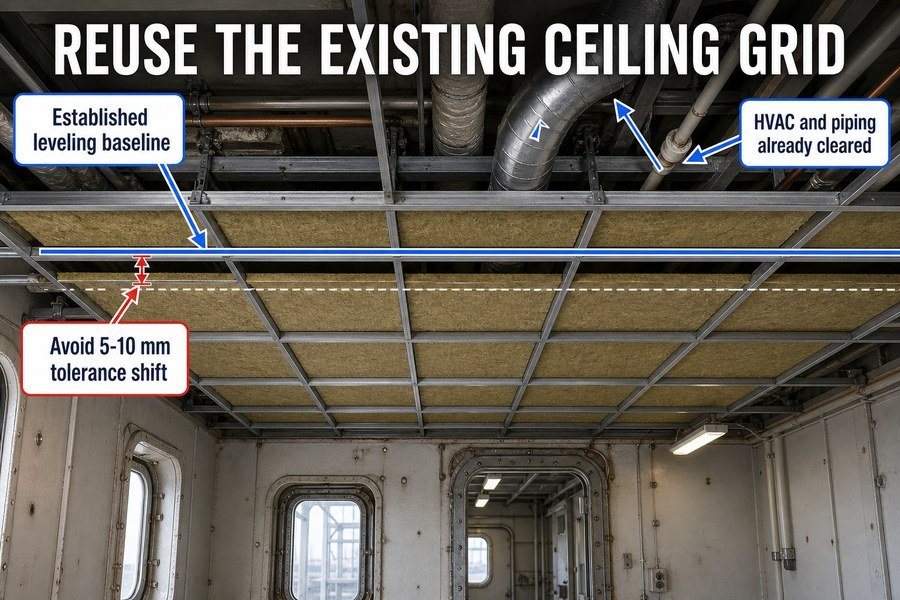
Preserving Established Leveling Baselines for Ceiling Panels
When you undertake interior decoration projects for large shipyards, time is money. Shipyards want fast work. Tearing down the old ceiling grid is a mistake. The old grid already has an established leveling baseline. Over the years, the ship has settled2. The old grid settled with it. If you install a brand new grid, you are working against the current shape of the ship. This causes 5mm to 10mm tolerance shifts3.
When you attach new 300mm wide C-type ceiling panels to a new grid on an old ship, the panels will not sit flat. You will see small gaps between every panel. By reusing the old carrier system, you preserve the established leveling baseline. The old grid is already perfectly horizontal relative to the current deck. Your new panels will snap in cleanly without gaps.
Maintaining Original Integration with HVAC and Piping
The second mechanism is maintaining original integration with HVAC and piping clashes. Above the ceiling panel, there is a mess of pipes and cables. The ISO 7547 standard dictates strict spacing for marine HVAC ducts. The original builders spent weeks cutting the old grid to fit around these ducts. If you build a new grid, you have to measure and cut around all those obstacles again.
If you make a mistake, the new grid will push against a pipe. This pushes the ceiling panel down, creating a gap. Reusing the existing grid avoids this completely. The old grid already clears the pipes. I always advise procurement officers to check the condition of the old grid. If the galvanized steel is not heavily rusted4, buy compatible ceiling panels from your Asian supplier and use the old grid. It controls your lead time and stops fit issues.
| Grid Strategy | Leveling Accuracy | HVAC/Piping Conflict Risk |
|---|---|---|
| Reusing Old Grid | High (matches current ship settlement) | Low (already cut to fit pipes) |
| Installing New Grid | Low (causes 5mm - 10mm shifts) | High (requires new cuts around obstacles) |
What Dimensional Tolerances Complicate Fitting Marine Wall Panels to Aged Steel Bulkheads?
Old ship bulkheads are never flat. If you expect a perfectly flat surface, your new panels will clash with the steel. This leads to rejected work by strict shipyard quality inspectors.
Fitting panels to aged steel bulkheads is complicated by three specific tolerances: steel plate out-of-flatness up to 8mm per meter, deck camber deviations, and welding distortion bumps of 3mm to 5mm. These structural variations prevent rigid marine panels from sitting flush against the structural boundaries.
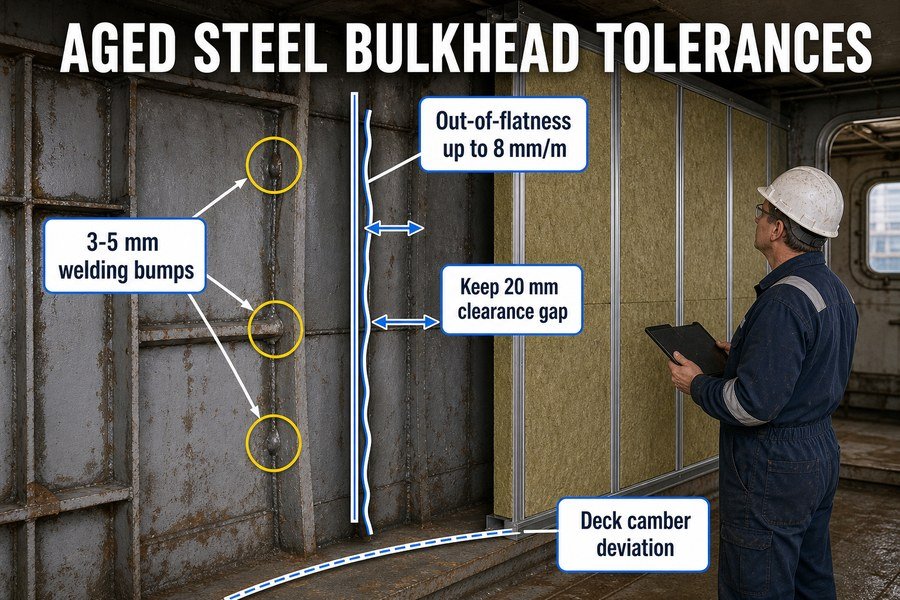
Adapting to Steel Plate Out-of-Flatness and Deck Camber
Shipyards in Europe and the United States have strict inspection rules. They will check your panel installation carefully. You cannot just push a wall panel against an old steel bulkhead and expect it to fit. The first tolerance you face is steel plate out-of-flatness. According to the IACS Recommendation 47 standard, shipbuilding quality standards allow for steel plates to be out of flat by up to 8mm per meter during original construction. After 20 years at sea, this number gets worse.5
The second tolerance is deck camber deviation. The deck of a ship curves down toward the sides to let water run off.6 Over time, this camber becomes uneven. If you try to build a perfectly straight cabin against an out-of-flat bulkhead with uneven deck camber, the panel will hit the steel in some places and have a huge gap in others.
Overcoming Welding Distortion Bumps During Installation
The third tolerance is welding distortion bumps. When the ship was repaired in the past, welders added new steel plates. Welding heat causes the steel to pull and distort.7 These distortion bumps are usually 3mm to 5mm high. A standard 50mm marine wall panel is very rigid. If it hits a 5mm welding bump, the panel will tilt. This ruins the entire wall alignment.
To solve these three tolerances, you must leave an air gap. SOLAS regulations actually prefer an air gap for insulation purposes. I recommend keeping a minimum 20mm clearance gap between the back of your new marine panel and the steel bulkhead. You adjust the bottom U-track 20mm away from the worst bump on the steel wall. This hides the out-of-flatness, covers the camber deviation, and clears the welding bumps.
| Structural Tolerance | Typical Deviation Size | Impact on Retrofit Panel |
|---|---|---|
| Steel Out-of-Flatness | Up to 8mm per meter | Panel hits steel, pushes wall out of plumb |
| Deck Camber Deviation | Varies along ship width | Bottom track does not sit flat on deck |
| Welding Distortion Bumps | 3mm to 5mm bumps | Causes panel to tilt away from the wall |
How Do Mismatched Thicknesses Complicate Marine Wall and Ceiling Panel Retrofits?
Ordering standard 50mm panels seems safe. But if the old ship panels were 25mm, your new doors and windows will not fit. You lose valuable time fixing these connection points.
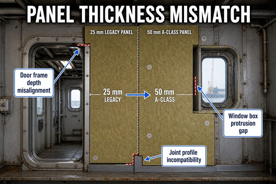
Mismatched panel thicknesses complicate retrofits by causing three major integration failures: door frame depth misalignment, window box protrusion, and joint profile incompatibility. Replacing a legacy 25mm panel with a modern 50mm A-Class panel requires custom frame extensions and compromises the established cabin footprint.
Addressing Door Frame Depth and Window Box Protrusion
When you source high-quality ship interior products from developing countries like China or Vietnam, you usually buy standard sizes. Today, the standard marine wall panel is 50mm thick.8 But older ships often used 25mm or 35mm panels. This thickness mismatch causes severe door frame depth misalignment. A standard A-60 marine fire door is built for a 50mm wall.9 If you install a 50mm wall into a space that used to have a 25mm wall, the old door frames will not fit. You must order new doors with a 50mm frame depth, or build custom steel extensions.
The second failure is window box protrusion. Cabins have windows looking out to the sea. The window box is a metal frame connecting the window to the wall panel. If you upgrade from a 25mm panel to a 50mm panel, the wall is now 25mm closer to the center of the room. The old window box will be too short. It will not reach the new panel face. This leaves an ugly gap around the window that fails fire inspections.10
Solving Joint Profile Incompatibility in Wall Panels
The third failure is joint profile incompatibility. Old panels often used a different joining system. Some used H-profiles, while modern panels mostly use a tongue-and-groove system.11 If you try to mix a new 50mm panel with an old 25mm wall section, the joints will never match. You will have a 25mm step in the middle of your wall.
To fix this, you must survey the ship before buying. Do not assume all walls are 50mm. If you find old 25mm walls, you have two choices. You can ask your Asian supplier to manufacture custom 25mm B-15 rated panels, which cost more. Or, you replace the entire wall system, including new A-class fire doors with 100mm to 125mm adjustable frames. I always advise replacing the doors together with the panels to avoid these integration failures.
| Thickness Mismatch Failure | Cause of Failure | Recommended Solution |
|---|---|---|
| Door Frame Misalignment | New 50mm panel on old 25mm door frame | Order adjustable door frames (100mm-125mm) |
| Window Box Protrusion | Wall moves 25mm into the cabin space | Install custom depth window box extensions |
| Joint Incompatibility | H-profile does not match tongue-and-groove | Replace the entire wall section, avoid mixing |
How Does 3D Laser Scanning Ensure Precise Marine Wall and Ceiling Panel Fit?
Manual tape measurements cause errors. If the numbers are wrong, the factory in Asia makes the wrong size panels. 3D scanning stops this and ensures a perfect fit upon delivery.
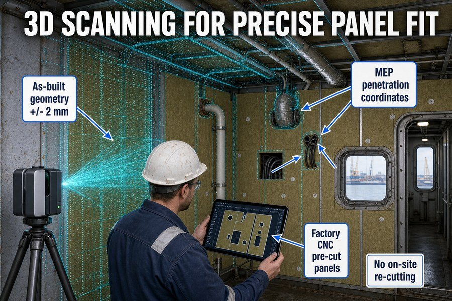
3D laser scanning ensures precise panel fit by capturing two critical datasets: exact as-built structural geometry with millimeter accuracy, and the exact locations of all MEP penetrations. This eliminates manual measurement errors and allows Asian factories to pre-cut panels perfectly before shipping.
Capturing As-Built Structural Geometry with Millimeter Accuracy
I tell all procurement officers that manual measurement is the enemy of profit. When workers use tape measures on an old ship, they make mistakes. 3D laser scanning solves this by capturing exact as-built structural geometry. The scanner shoots millions of laser points to create a point cloud.12 This point cloud has a high accuracy of +/- 2mm.13 It shows exactly how the hull bends, where the deck drops, and how much the bulkheads lean.
A scanner takes only 3 to 5 minutes per cabin.14 The data goes directly into CAD software. You can then send this exact digital model to your wall panel supplier in China. The factory can cut the panels to match the exact curve of the ship. When the panels arrive in Europe, they slide right into place. You do not need to cut panels on the ship. This reduces on-site cutting time by 80%.15
Mapping MEP Penetrations for Pre-Cut Panel Manufacturing
The second dataset is the exact location of all MEP penetrations. MEP stands for Mechanical, Electrical, and Plumbing. Every cabin has pipes, air conditioning ducts, and cable trays passing through the walls and ceilings. In the past, workers installed the wall panel, found the pipe, and cut a hole with a saw. This creates dangerous dust and ruins the clean finish of the panel.
3D scanning records the exact X and Y coordinates of every single pipe. You give these coordinates to the factory. The factory uses CNC machines to cut perfect holes for the MEP penetrations before painting or applying the PVC film. When your workers install the panel, the pre-cut hole slides perfectly over the pipe. This level of preparation impresses shipyard owners. It shows you control the quality and the lead time perfectly.
| Measurement Method | Accuracy Level | MEP Hole Cutting Location | On-Site Labor Time |
|---|---|---|---|
| Manual Tape Measure | +/- 15mm | Cut on the ship | Very High |
| 3D Laser Scanning | +/- 2mm | CNC pre-cut in the factory | Reduced by 80% |
How Do Legacy Fixing Points Misalign Retrofitted Marine Wall Panels?
Old ships have hidden steel brackets welded to the deck. If your new bottom tracks hit these old brackets, the walls skew. This ruins the whole cabin layout.
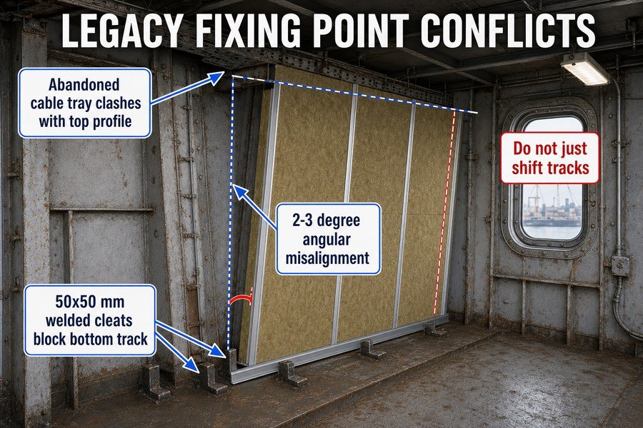
Legacy fixing points misalign retrofitted panels through two primary conflicts: bottom track obstruction by old welded deck cleats, and top profile clash with abandoned cable trays. These immovable obstacles force installers to shift the base track, causing angular misalignment across the entire wall span.
Managing Bottom Track Obstruction by Welded Deck Cleats
When you remove old marine panels, you rarely find a clean steel deck. You find legacy fixing points. The original builders welded small steel pieces, called cleats16, to the deck to hold the old walls. These cleats are usually heavy 50x50mm L-angles. This causes bottom track obstruction. Your new installation plan requires a straight line for the new bottom track. But the old welded cleats are right in the middle of your line.
Shipyard rules often forbid cutting or grinding old welds without special "hot work" permits.17 Hot work permits take days to get. So, your workers shift the new bottom track around the old cleat. They move the track 30mm to the left. This simple shift causes a 2-degree to 3-degree angular misalignment18 across the whole room. The wall is no longer square. When you try to install the marine ceiling panel later, the ceiling grid will not fit because the room is shaped like a diamond.
Preventing Top Profile Clash with Abandoned Cable Trays
The second conflict is the top profile clash with abandoned cable trays. Above the old wall, there are usually old electrical trays. Shipyards rarely pay to remove dead cables. They just leave them. Your new top profile needs a flat steel deck to mount against. But the abandoned cable tray blocks the path.
Again, if workers shift the top track to avoid the tray, the wall leans. A leaning wall cannot support a fire door properly.19 The heavy door will swing open on its own. To avoid this, you must do a thorough teardown inspection. If you find old cleats and trays, you must either secure hot work permits early or design custom brackets to bridge over the legacy fixing points. Do not just shift the tracks.
| Legacy Conflict Type | Typical Obstacle Size | Result if Track is Shifted |
|---|---|---|
| Bottom Track Obstruction | 50x50mm welded cleats | 2-3 degree angular misalignment |
| Top Profile Clash | 100mm wide cable trays | Wall leans, heavy fire doors fail to close |
Conclusion
Solving fit issues requires understanding hull deflection, strict tolerances, and thickness mismatches. By utilizing 3D scanning and reusing existing grids, you can easily control costs and satisfy shipyard demands with Asian materials.
-
"[PDF] bending and buckling of rectangular sandwich plates", https://ntrs.nasa.gov/api/citations/19930082873/downloads/19930082873.pdf. A structural-mechanics or sandwich-panel reference should be cited to show that panels restrained between supports can buckle under compressive loading when axial force exceeds their critical buckling capacity. Evidence role: mechanism; source type: paper. Supports: Rigidly fixed wall panels can buckle or bend when deck movement imposes compressive load on them.. Scope note: General buckling theory supports the mechanism, but panel-specific capacity depends on the tested marine panel construction, core, facings, fixings, and boundary conditions. ↩
-
"[PDF] impact of imperfections, residual stresses, erection fit-up and ...", https://www.eng.auburn.edu/files/centers/hrc/931-003.pdf. Naval-architecture literature describes ships as flexible structures that can experience hull girder deflection and local structural deformation over service life, which provides context for why existing interior reference lines may no longer match original design geometry. Evidence role: mechanism; source type: education. Supports: Over years of service, a ship’s structure can settle or deform enough that interior installations may reflect the vessel’s current geometry rather than its original geometry.. Scope note: This would support the general mechanism of in-service deformation, not prove that a particular ceiling grid remains level on any given vessel. ↩
-
"How to choose the right marine wall panels for marine interior ...", https://magellanmarinetech.com/how-choose-right-marine-wall-panels-for-marine-interior-projects/. Studies and shipbuilding guidance on hull-block assembly and outfitting tolerances document that millimetre-scale dimensional deviations occur during ship construction and alignment; this supports the plausibility of small fit-up shifts, though not the article’s exact 5–10 mm figure for ceiling grids. Evidence role: statistic; source type: paper. Supports: Replacing a ceiling grid on an older ship can create millimetre-scale alignment or tolerance deviations.. Scope note: The source may provide analogous shipbuilding or outfitting tolerance ranges rather than direct measurements for refurbished ceiling-panel grids. ↩
-
"[PDF] DoD 2013-3557", https://www.waru.edu/sites/default/files/Migrated/CopDocuments/Examination%20of%20Zinc%20Galvanized%20Steel%20Corrosion%20Rates%20in%20Various%20Atmospheric%20and%20Soil%20Exposure%20Conditions.pdf. Engineering references on galvanized steel explain that zinc coatings provide sacrificial corrosion protection, but corrosion, coating loss, and rusting reduce long-term durability in exposed or marine environments; this supports using corrosion condition as a screening criterion before reuse. Evidence role: mechanism; source type: government. Supports: The corrosion condition of galvanized steel is relevant when deciding whether an existing ceiling grid can be reused.. Scope note: This supports the relevance of rust inspection generally, not a precise acceptance threshold for reusing a specific ceiling carrier system. ↩
-
"Ultimate Strength, Corrosion, Fatigue, Fracture, and Systems", https://www.ctsm.umd.edu/archive/ayyubbmstambaug02639.pdf. Research on aging ship structures describes how corrosion, fatigue, loading history, and repair processes can degrade hull geometry and structural condition over service life, providing contextual support for increased deviation in older vessels. Evidence role: general_support; source type: paper. Supports: Steel plate flatness and hull condition can deteriorate over long service periods, making older ships more likely to deviate from original construction tolerances.. Scope note: Such sources generally support age-related structural degradation but may not prove that an 8 mm/m flatness tolerance specifically worsens after exactly 20 years for all ships. ↩
-
"[PDF] Principles of Ship Performance Course Notes - USNA", https://www.usna.edu/NAOE/_files/documents/Courses/EN400/EN400_Course_Notes,_Summer_2020.pdf. Naval architecture references define deck camber as the transverse curvature of a deck, traditionally used to shed water toward the ship sides, supporting the functional explanation of camber. Evidence role: definition; source type: education. Supports: Ship decks commonly have transverse camber so water can drain toward the sides.. Scope note: This supports the general naval-architecture definition and purpose of camber, not the degree of camber deviation on a particular vessel. ↩
-
"[PDF] Evaluation of Residual Stresses in Isothermal Friction Stir Welded ...", https://www.osti.gov/servlets/purl/1817344. Engineering literature on welding residual stress and distortion explains that localized heating and cooling produce shrinkage strains and residual stresses that can deform steel plates, supporting the stated mechanism. Evidence role: mechanism; source type: paper. Supports: Welding heat can create shrinkage, residual stress, and distortion in steel structures.. Scope note: The mechanism is well established, but the exact height of installation bumps depends on plate thickness, weld procedure, restraint, and repair history. ↩
-
"How to choose the right marine wall panels for marine interior ...", https://magellanmarinetech.com/how-choose-right-marine-wall-panels-for-marine-interior-projects/. A classification-society or type-approval source describing marine accommodation wall panels with a nominal 50 mm thickness supports the claim that 50 mm is a common contemporary specification for such panels. Evidence role: general_support; source type: institution. Supports: Contemporary marine interior wall panels are commonly supplied in 50 mm thickness.. Scope note: This would support common industry practice, not prove that 50 mm is the only or universally required standard. ↩
-
"How to choose the right marine fire door for different ship ...", https://magellanmarinetech.com/how-to-choose-right-marine-fire-door-for-different-ship-compartments/. IMO and classification-society materials on A-class fire divisions and approved fire-door assemblies support that A-60 doors must be installed as part of tested fire-resisting divisions with compatible frames and surrounding structures. Evidence role: mechanism; source type: institution. Supports: An A-60 marine fire door must match the approved fire-rated wall or bulkhead assembly, including the frame interface.. Scope note: Such sources generally establish the need for compatible tested assemblies, but may not state that every A-60 door is built specifically for a 50 mm wall. ↩
-
"What Is the Purpose and Scope of the IMO FTP Code?", https://magellanmarinetech.com/what-purpose-scope-of-imo-ftp-code/. Guidance on shipboard fire divisions and penetrations supports that unsealed or non-approved gaps around openings can compromise the required fire integrity of accommodation boundaries. Evidence role: mechanism; source type: government. Supports: A gap around a window-box interface in a fire-rated ship interior boundary can create a fire-integrity compliance problem.. Scope note: The source would substantiate the fire-integrity principle; whether a specific window-box gap fails inspection depends on the vessel’s approved drawings, flag-state rules, and surveyor judgment. ↩
-
"What are Marine Wall Panels?", https://magellanmarinetech.com/what-are-marine-wall-panels/. Technical literature on prefabricated ship accommodation systems supports that wall panels have used different edge-joint systems, including profile-based and tongue-and-groove connections, which can affect interchangeability. Evidence role: historical_context; source type: research. Supports: Marine accommodation wall panels can use different joint profiles, and profile incompatibility can affect retrofit work.. Scope note: This supports the existence and relevance of differing joint systems, but may not quantify how often each system was used across all ship eras and builders. ↩
-
"Quantification of Urban Forest Carbon Stocks Using Terrestrial ...", https://www.aces.edu/blog/topics/forestry/quantification-of-urban-forest-carbon-stocks-using-terrestrial-laser-scanning-technology/. A technical source on terrestrial laser scanning supports that laser scanners collect large numbers of three-dimensional point measurements and represent them as point clouds for documenting existing geometry. Evidence role: mechanism; source type: education. Supports: 3D laser scanners capture many laser measurements and use them to create a point cloud.. Scope note: The source may describe the general scanning mechanism rather than this specific ship-interior workflow. ↩
-
"A Method for Point Cloud Accuracy Analysis Based on Intensity ...", https://pmc.ncbi.nlm.nih.gov/articles/PMC10675609/. A metrology or laser-scanning specification source can support that some terrestrial laser scanners achieve millimeter-level ranging or 3D-point accuracy under defined conditions. Evidence role: statistic; source type: research. Supports: A 3D laser-scanning point cloud can have approximately ±2 mm accuracy.. Scope note: Accuracy depends on scanner model, range, surface properties, registration workflow, and field conditions; a general source would not prove every cabin scan achieves ±2 mm. ↩
-
"Utilizing a Terrestrial Laser Scanner for 3D Luminance ... - PMC - NIH", https://pmc.ncbi.nlm.nih.gov/articles/PMC8321338/. An applied case study or technical guidance document can support typical terrestrial laser-scanning capture times for small interior spaces, including setup and scan duration where available. Evidence role: case_reference; source type: paper. Supports: A 3D scanner can capture a cabin-sized interior space in about 3 to 5 minutes.. Scope note: Scan time is highly workflow-specific and varies with scanner model, resolution settings, number of stations, cabin size, and required registration quality. ↩
-
"How 3D Laser Scanning Helps Create Precise As-Built ...", https://www.academia.edu/128250415/How_3D_Laser_Scanning_Helps_Create_Precise_As_Built_Drawings. A construction or shipbuilding digital-fabrication study can support that laser scanning combined with off-site prefabrication can reduce field rework or on-site fitting labor by enabling components to be fabricated from as-built geometry. Evidence role: general_support; source type: paper. Supports: Using scan-derived as-built data for prefabrication can substantially reduce on-site cutting or rework time.. Scope note: The exact 80% reduction would need project-specific measurement; broader studies may only support the direction of labor reduction, not this precise percentage. ↩
-
"[PDF] Print Pat0001.TIF (22 pages) - ROSA P", https://rosap.ntl.bts.gov/view/dot/64061/dot_64061_DS1.pdf. A shipbuilding or marine-construction reference should document that welded cleats or similar small steel attachments are commonly used as fixing or support points on steel structures, supporting the terminology used here. Evidence role: definition; source type: institution. Supports: The original builders welded small steel pieces, called cleats, to the deck to hold the old walls.. Scope note: The source may support the general use of cleats in ship construction rather than the specific 50x50 mm dimensions described in this article. ↩
-
"1917.152 - Welding, cutting and heating (hot work)[12] (See ... - OSHA", http://www.osha.gov/laws-regs/regulations/standardnumber/1917/1917.152. Occupational-safety guidance generally classifies welding, cutting, and grinding that can generate heat or sparks as hot work requiring controlled authorization, supporting the need for permits before altering welded steel in shipyard settings. Evidence role: expert_consensus; source type: government. Supports: Shipyard rules often forbid cutting or grinding old welds without special hot work permits.. Scope note: Such guidance supports the general safety-control requirement; individual shipyard permit timelines and procedures vary. ↩
-
"[PDF] OER Math 1060 – Trigonometry - SLCC", https://www.slcc.edu/math/docs/oer-trigonometry.pdf. A basic trigonometry source can substantiate that a lateral offset over a short wall run produces an angular deviation according to arctangent geometry, providing contextual support for the stated misalignment range. Evidence role: mechanism; source type: education. Supports: Moving the bottom track around a cleat can create a 2-degree to 3-degree angular misalignment across the room.. Scope note: The source would support the geometric relationship, but the exact 2–3 degree value depends on the wall length and offset assumed in the installation example. ↩
-
"[PDF] WRCRWA STEEL DOORS AND FRAMES AERATION UPGRADE ...", https://westernwaterca.gov/documentview.aspx?did=581. Fire-door installation and inspection guidance commonly requires door frames and assemblies to be installed plumb, level, square, and aligned so that the door can close and latch as intended, supporting the link between wall/frame misalignment and impaired fire-door operation. Evidence role: expert_consensus; source type: institution. Supports: A leaning wall cannot support a fire door properly, and the door may fail to close correctly.. Scope note: The source would support proper alignment requirements for fire-door assemblies; it may not directly evaluate the specific leaning-wall scenario described here. ↩