Old ship refits often turn into expensive nightmares. Existing steel bulkheads block new panels and ruin your schedule. I will show you how to master these structural hurdles today.
Retained structures complicate marine panel replacement by imposing four main hurdles: inflexible existing steel frames, concealed live utility networks, distorted substrate foundations, and strict fire boundary overlapping requirements. These factors force installation crews to use custom panel modifications and phased sequences instead of standard plug-and-play assembly methods.
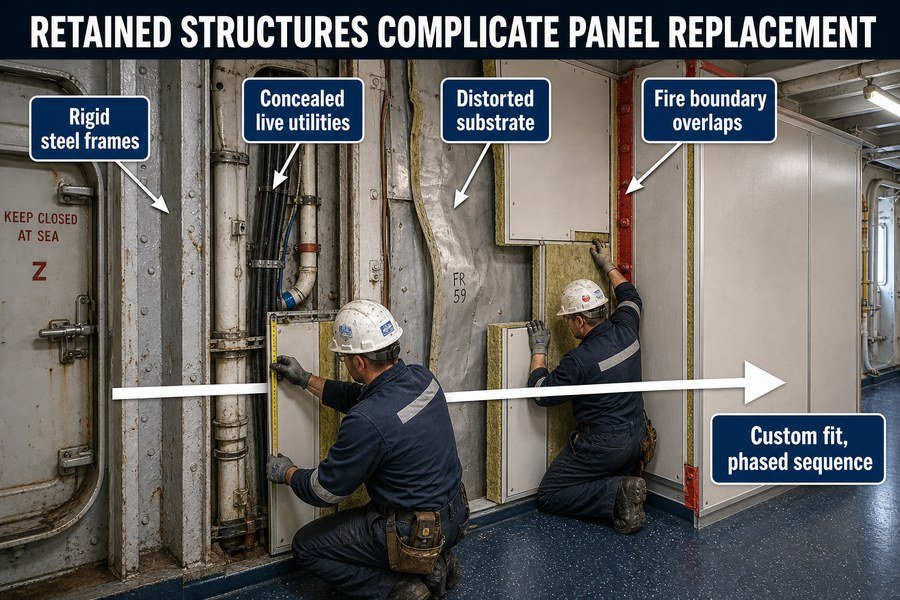
You cannot simply rip out old panels and slap new ones in. Let us look at the specific obstacles that make this process so tough and how you can overcome them.
How Do Existing Steel Frames Restrict Retrofitted Marine Wall Panel Positioning?
Rigid steel frames often clash with new panel designs. This mismatch wastes expensive labor hours. We must measure and adapt to these steel grids before we order materials.
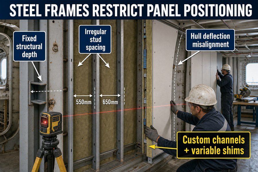
Existing steel frames restrict retrofitted marine wall panel positioning through three main factors: rigid structural depths that limit panel thickness, irregular stud spacing that breaks standard panel widths, and structural hull deflection that causes misalignment. Installers must use custom framing channels and variable shims to fix these constraints.
Ignoring the old steel layout will lead to a disastrous installation. You must understand how the existing grid forces your hand.
Managing Rigid Structural Depths in Marine Panel Retrofits
Existing steel bulkheads have fixed depths. When I started at the factory, I saw many projects fail because the new panel was too thick for the old steel track. According to ship construction standards like ISO 3078, standard steel C-channels have a depth of 50mm to 100mm. If your new marine wall panel is 50mm thick, but the existing frame only offers 30mm of clearance because of added stiffeners, you cannot force it in. You must either use a thinner panel or install a secondary extension track to push the mounting surface outward. This depth limit restricts your choices during the procurement phase. You must measure the track depth across the entire cabin to avoid buying useless materials that will not fit the existing footprint.
Dealing with Irregular Stud Spacing and Structural Hull Deflection
Older ships do not have perfect 600mm stud spacing. Over time, shipyards added custom supports and welded temporary brackets1. This irregular spacing breaks the standard panel width. If you buy standard 600mm panels, their joints will not line up with the old 550mm or 650mm spaced studs. You must cut the panels on-site to match the old studs. Furthermore, structural hull deflection causes huge problems. Ships bend at sea.2 After 15 years, a steel frame might bow outward by 10mm to 15mm. Standard SOLAS guidelines state that panel joints must remain tight, with gaps not exceeding 3mm3, to maintain fire integrity. When the steel bows, the straight panel will not fit flat. We solve this by installing variable steel shims behind the mounting tracks. The shims fill the gap between the bent steel and the straight panel. You must use a laser level to map the irregular stud spacing and the deflection before cutting any expensive marine wall panel.
| Constraint Factor | Technical Impact on Installation | Professional Solution |
|---|---|---|
| Rigid Structural Depths | Panel cannot fit into existing tracks | Install secondary extension tracks or use thinner panels |
| Irregular Stud Spacing | Panel joints do not align with steel studs | Custom cut panels on-site to match existing spacing |
| Structural Hull Deflection | Straight panels bend or leave large gaps | Install variable steel shims to level the mounting tracks |
Why Must Marine Wall Panel Retrofits Isolate Concealed Live Pipework and Cabling?
Hidden pipes and cables are dangerous traps behind old panels. Cutting into them causes ship-wide blackouts or floods. We must isolate them to protect the ship and crew.
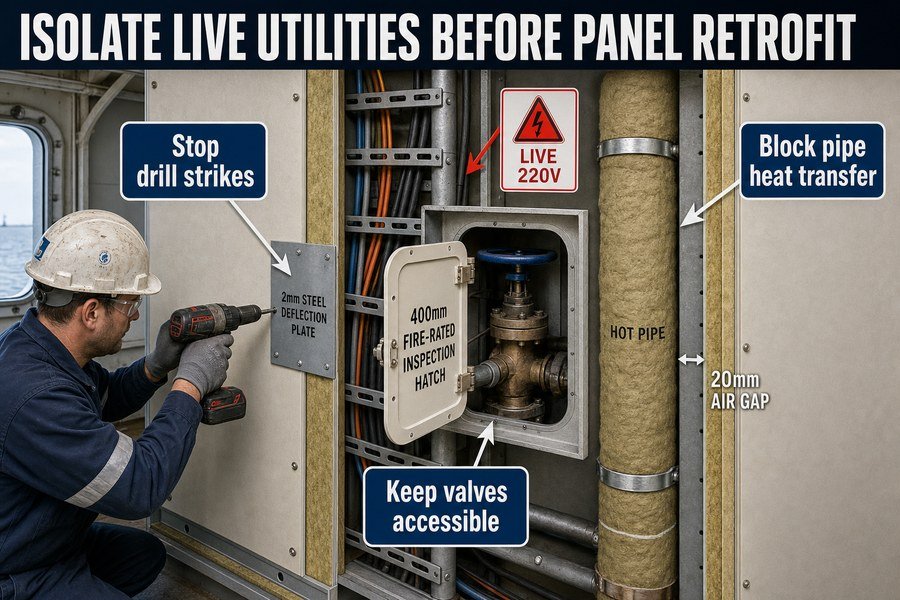
Marine wall panel retrofits must isolate concealed live pipework and cabling for three critical reasons: preventing accidental mechanical strikes during drilling, ensuring easy maintenance access via inspection hatches, and stopping thermal transfer from hot pipes to panel cores. This isolation guarantees ship safety and complies with electrical codes.
You can ruin a project in one second if your drill hits a live cable. Let us explore why isolating these utilities is a non-negotiable step.
Preventing Accidental Mechanical Strikes on Live Ship Utilities
When you install new marine wall panels, you use self-tapping screws and power drills. Behind the old panels, there are live 220V cables and pressurized water pipes. If you do not locate and isolate these utilities, a 25mm screw can easily pierce a live wire. This mechanical strike causes electrical shorts, sparks, and immediate fires.4 According to IEEE 45 standards for electrical installations on ships5, wiring must have physical protection from interior outfitting fasteners. I always tell my shipyard clients to use electronic pipe locators before doing any work. We must install 2mm thick steel deflection plates over existing cable trays inside the wall. This physical isolation stops the drill bit from hitting the live network, saving lives and preventing massive electrical repair bills.
Ensuring Maintenance Access and Stopping Pipe Thermal Transfer
The second reason we isolate these networks is for future maintenance access. Classification societies like DNV mandate that pipe valves, flanges, and electrical junction boxes must remain easily accessible. If you cover them permanently with a solid marine wall panel, you violate these rules. You must isolate the utility zone by building a dedicated service cavity and installing 400mm by 400mm fire-rated inspection hatches directly over the valves. The third reason is thermal transfer. Engine exhaust pipes or steam lines get very hot, often exceeding 80 degrees Celsius. If a new panel touches these hot pipes directly, the heat will degrade the panel core or melt the surface PVC decorative film.6 You must isolate the pipes using mineral wool sleeves with a density of 100 kg/m3 to block the heat. You must also leave at least a 20mm air gap between the insulated pipe and the back of the marine wall panel.
| Isolation Reason | Consequence of Failure | Required Isolation Method |
|---|---|---|
| Prevent Mechanical Strikes | Electrical fires and pressurized pipe leaks | Install 2mm steel deflection plates over utility trays |
| Ensure Maintenance Access | Violation of DNV classification rules | Build service cavities and install fire-rated hatches |
| Stop Thermal Transfer | Melted PVC film and degraded panel core | Use 100 kg/m3 mineral wool sleeves and a 20mm air gap |
How Do Uneven Existing Substrates Complicate Marine Ceiling Panel Suspension on Older Ships?
A bumpy deck ceiling ruins the suspension of new panels. This causes wavy, ugly ceilings that fail inspections. We must level the playing field before hanging anything.
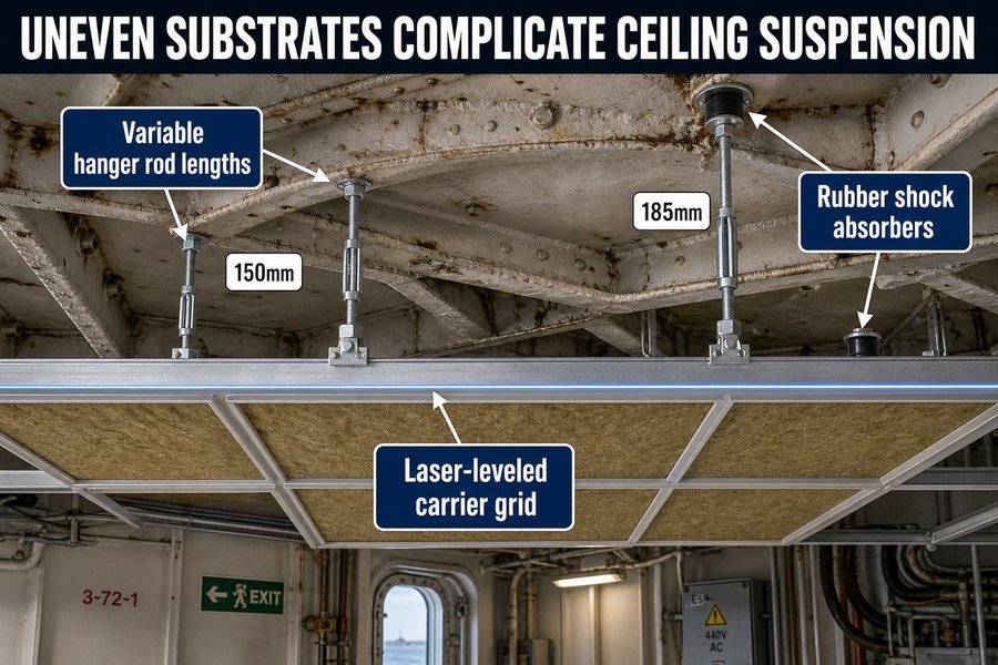
Uneven existing substrates complicate marine ceiling panel suspension by introducing three issues: unpredictable hanger rod lengths, skewed carrier track alignments, and compromised vibration damping. Installers must counter these variations by using adjustable threaded suspension rods, laser-leveled primary grids, and flexible rubber shock absorbers to create a flat finish.
A flat ceiling requires a perfect suspension system. Let us look at how an uneven overhead steel deck fights against a smooth ceiling finish.
Managing Unpredictable Hanger Rod Lengths on Uneven Decks
On an old ship, the overhead steel deck is never flat. Decades of heavy cargo loads and welding repairs warp the steel plates.7 When you suspend a new marine ceiling panel, you attach hanger rods to this overhead steel. Because the deck is uneven, the distance from the deck down to the desired ceiling line changes constantly. You cannot use fixed-length rods for the whole room. One spot might need a 150mm rod, and a spot one meter away might need a 185mm rod. To solve this complication, you must use M6 or M8 threaded rods equipped with adjustable turnbuckles8. This hardware allows the installation team to screw the rod up or down, adjusting the height of every single hanger to compensate perfectly for the bumpy substrate above.
Correcting Carrier Track Alignments and Restoring Vibration Damping
The second issue is skewed carrier track alignment. When the deck is uneven, the mounting brackets sit at different angles. If you bolt the carrier track directly to these crooked brackets, the track will twist. A twisted track will not hold the marine ceiling panel securely, causing the panels to drop out. To fix this, you must construct a primary grid suspended by laser levels to ensure a perfectly horizontal plane, completely independent of the steel deck above. The third issue is compromised vibration damping. Ships vibrate intensely. IMO regulations require secure fittings to prevent acoustic noise.9 On an uneven deck, rigid mounts will experience uneven stress and break under vibration. You must install flexible rubber shock absorbers, typically rated to dampen 15 to 20 Hz frequencies10, between the steel deck and the hanger rod to absorb the kinetic energy evenly.
| Suspension Complication | Root Cause | Technical Correction Strategy |
|---|---|---|
| Unpredictable Rod Lengths | Warped and uneven steel deck plates | Use M6/M8 threaded rods with adjustable turnbuckles |
| Skewed Track Alignments | Crooked mounting brackets on bumpy steel | Suspend a laser-leveled primary grid system |
| Compromised Vibration Damping | Uneven stress distribution on rigid mounts | Install rubber shock absorbers rated for 15-20 Hz |
How Does Maintaining A-Class and B-Class Fire Ratings Complicate Marine Wall Panel Retrofits?
Fire ratings are a matter of life and death. Mixing old boundaries with new panels often creates deadly gaps. We must strictly follow fire safety rules during retrofits.
Maintaining A-Class and B-Class fire ratings complicates marine wall panel retrofits through three strict requirements: seamless integration with existing fire boundaries, mandatory use of certified intumescent joint sealants, and exact matching of core insulation densities. Failing any of these steps voids the SOLAS certification of the entire bulkhead.
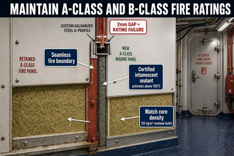
You cannot gamble with fire safety. Let us examine how strict fire regulations make panel retrofits a highly technical challenge.
Achieving Seamless Integration with Existing A-Class and B-Class Boundaries
Fire protection on a ship works like a sealed box. According to SOLAS Chapter II-2 regulations, an A-60 bulkhead must stop fire and smoke for a full 60 minutes11. When you replace a damaged marine wall panel, you must connect the new panel directly to the old panels that you are keeping. This integration is extremely difficult. The edge profiles of the new panel might not perfectly lock into the 20-year-old adjacent panel due to different manufacturing designs. If there is even a 2mm gap between them, smoke will pass through, and the fire rating fails immediately.12 You must fabricate custom U-profiles from 1.5mm galvanized steel to bridge the gap. You must then mechanically lock the new B-15 or A-0 panel into the existing fire boundary using heavy-duty steel rivets, ensuring absolutely no gaps exist.
Applying Certified Intumescent Sealants and Matching Insulation Densities
The second strict requirement is the mandatory use of certified intumescent joint sealants. Standard commercial silicone will burn away immediately in a ship fire. You must use marine-grade intumescent sealants that expand rapidly when exposed to heat above 150 degrees Celsius. Every joint between the new panel and the old structure must be fully filled with this specific sealant to block smoke. The third complication is matching the core insulation density exactly. If the original A-Class bulkhead used rockwool with a density of 120 kg/m3, you cannot replace a section with a cheaper panel that uses 100 kg/m3 rockwool.13 The heat transfer rate will be uneven. The surveyor from the classification society will check the material certificates. You must procure replacement panels with the exact same core density to maintain the thermal integrity.
| Fire Rating Requirement | Critical Material Used | SOLAS Compliance Goal |
|---|---|---|
| Seamless Boundary Integration | 1.5mm galvanized steel custom U-profiles | Prevent smoke and flame passage through gaps |
| Mandatory Joint Sealing | Intumescent sealant activating at 150°C | Block toxic smoke during high-temperature fires |
| Matching Insulation Density | Rockwool core matching existing (e.g., 120 kg/m3) | Maintain consistent thermal insulation across the wall |
How Do Retained Adjacent Panels Constrain Marine Ceiling Panel Replacement Sequences?
Pulling down one panel can easily break the next one. This domino effect slows down the whole job. We must carefully plan the order of removal and installation.
Retained adjacent panels constrain marine ceiling panel replacement sequences by enforcing three strict rules: requiring sequential unlocking from a fixed starting point, preventing lateral sliding due to tight interlocking profiles, and demanding delicate temporary edge support to prevent damage to the old panels remaining in place.
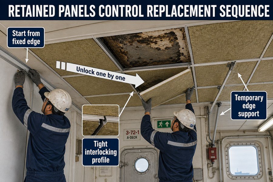
You cannot work in a random order when dealing with interlocked systems. Let us break down how the old panels dictate your every move.
Managing Sequential Unlocking and Tight Interlocking Profiles
Marine ceiling panels are designed to interlock tightly to prevent rattling during engine operation.14 Most strip ceilings or square tile ceilings use a tongue-and-groove or a rigid clip-in edge profile.15 When you need to replace just a few damaged panels in the middle of a room, the retained adjacent panels block your way. You cannot simply pull a middle panel straight down. The first rule is that you must start from a fixed unlocking point, usually at the very edge of the bulkhead. You must remove the edge trim and sequentially unlock the panels one by one until you reach the damaged area. The second rule is that the tight interlocking profiles prevent lateral sliding. You cannot slide the new panel into place horizontally. You must angle it perfectly into the carrier track and push it upward without scratching the painted surface of the old panels next to it.
Providing Delicate Temporary Edge Support for Retained Panels
The third rule involves temporary edge support, which is often forgotten. When you remove a section of the marine ceiling panel system, the adjacent panels lose their structural tension. The carrier track might sag because the weight distribution changes suddenly. If you leave the retained panels hanging without support, their edges will bend or their mounting clips will snap under the constant vibration of the ship. You must install temporary aluminum support bars across the exposed edges. These bars hold the old panels firmly in place and keep the track straight while you prepare and cut the new ceiling panels. I have seen interior contractors skip this step to save time, and they ended up having to replace the entire ceiling because the old panels cracked under their own unsupported weight.
| Sequence Constraint | Installation Action Required | Reason for Action |
|---|---|---|
| Sequential Unlocking | Remove panels from the edge inward | Prevents breaking the interlocked tongue-and-groove |
| Interlocking Profiles | Angle the new panel upward precisely | Avoids scratching the paint on retained adjacent panels |
| Loss of Structural Tension | Install temporary aluminum support bars | Prevents old panels from bending or snapping off |
How Do Existing Service Penetrations Dictate Marine Wall Panel Retrofit Planning?
Cables and pipes punching through walls require special treatment. If you cut the holes wrong, you ruin the panel. We must map every penetration before cutting begins.
Existing service penetrations dictate marine wall panel retrofit planning by imposing three necessities: precise template mapping of complex hole locations, specialized cutting tools to prevent panel delamination, and retrofitting split-frame transit frames around existing cables. These steps ensure penetrations remain fully sealed without disconnecting live ship services.
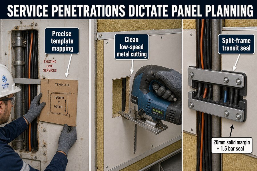
A wall panel is useless if the holes for pipes and cables do not align perfectly. Let us explore the strict planning required for these penetrations.
Executing Precise Template Mapping and Preventing Panel Delamination
When you install a new marine wall panel around existing pipes, you cannot guess the hole locations. The first necessity is precise template mapping. You must create a rigid cardboard or thin plywood template of the exact penetration layout on the old bulkhead. A standard electrical cable transit might measure exactly 120mm by 60mm. If your cut on the new panel is off by even 5mm, the transit frame will not fit, and the expensive panel goes straight into the trash. The second necessity is using specialized cutting tools. A marine wall panel has a thin metal skin and a bonded rockwool core.16 If you use a standard wood saw, the metal skin will tear aggressively, and the core will delaminate from the steel. You must use fine-toothed jigsaw blades rated specifically for sheet metal and cut at a low speed to keep the PVC film and steel skin intact.
Installing Split-Frame Transit Frames Around Existing Cables
The third and most complex necessity is retrofitting transit frames. In a new ship, you pull the cables through the hole after the panel is up. In a retrofit, the cables are already there, and you cannot cut them. You must install the panel around the live cables. To seal this penetration to A-60 or B-15 standards17, you must use split-frame transit systems. The split frame bolts together in two halves around the existing cables. Then, you insert peelable rubber modules around each individual cable to seal the gaps tightly. According to IMO regulations, these transits must withstand a water pressure test of 1.5 bar and stop fire.18 You must plan the panel cut-out perfectly so the split frame has enough solid steel margin, usually a minimum of 20mm on all sides, to bolt into the new marine wall panel safely.
| Penetration Necessity | Required Action | Goal for Retrofit Planning |
|---|---|---|
| Precise Template Mapping | Measure and create cardboard templates | Ensure the 120mm x 60mm hole aligns perfectly |
| Specialized Cutting Tools | Use fine-toothed metal jigsaw blades | Prevent metal skin tearing and core delamination |
| Split-Frame Transit Frames | Bolt two halves around live cables | Withstand 1.5 bar water pressure and stop fire |
Conclusion
Retained structures make panel retrofits highly complex. By managing steel frames, live utilities, uneven decks, fire ratings, interlocked systems, and penetrations, you ensure a safe, successful marine outfitting project.
-
"Process: Fabricating and Repairing Large Structural Components", http://www.osha.gov/ship-building-repair/fabricating. Guidance on ship repair and conversion surveys describes how existing vessels may contain modifications, repairs, and added structural members that differ from original drawings, supporting the need to verify actual onboard framing before retrofit work. Evidence role: general_support; source type: institution. Supports: Older ships may have nonstandard framing because shipyards have added custom supports or welded brackets over time.. Scope note: Such sources usually support the general prevalence of alterations in repaired or converted vessels, not the exact frequency of custom supports or temporary brackets on all older ships. ↩
-
"[PDF] Assessment of Cumulative Lifetime Seaway Loads for Ships", https://ctsm.umd.edu/archive-papers/sikorajpmichael16718.pdf. Naval architecture literature on longitudinal hull-girder strength explains that wave loading and vessel loading conditions produce hogging and sagging bending moments, supporting the statement that ships undergo bending while at sea. Evidence role: mechanism; source type: education. Supports: Ships bend at sea because wave and loading conditions create hull-girder bending and deflection.. Scope note: This establishes the physical mechanism of hull bending but does not quantify the 10–15 mm frame bowing described for a particular retrofit case. ↩
-
"Are Marine Fire Divisions the Same as Marine Panel Ratings?", https://magellanmarinetech.com/are-marine-fire-divisions-same-as-marine-panel-ratings/. An IMO SOLAS, FTP Code, or recognized approval document specifying permissible joint tolerances for fire-rated marine bulkhead assemblies would substantiate the stated 3 mm gap limit as a fire-integrity requirement. Evidence role: expert_consensus; source type: institution. Supports: Panel joints in fire-rated marine bulkheads must keep gaps at or below 3 mm to maintain fire integrity.. Scope note: SOLAS generally establishes fire-safety performance requirements, while exact joint-gap tolerances may appear in test procedures, type approvals, or installation manuals for specific assemblies rather than as a universal SOLAS rule. ↩
-
"[PDF] The ability for investigators to visible identify and interpret damage to ...", https://encompass.eku.edu/cgi/viewcontent.cgi?article=1589&context=etd. Electrical-safety guidance identifies mechanical damage to energized conductors as a cause of short circuits, arcing, shock hazards, and ignition of surrounding materials. Evidence role: mechanism; source type: government. Supports: A drill or screw striking an energized cable can produce shorts, sparks/arcing, and fire hazards.. Scope note: Such sources generally establish the hazard mechanism; they may not quantify the probability of fire in the specific marine wall-panel installation described. ↩
-
"Update to Electrical Engineering Regulations - Federal Register", https://www.federalregister.gov/documents/2023/03/16/2023-04370/update-to-electrical-engineering-regulations. IEEE Std 45 provides recommended practice for shipboard electrical installations, including requirements and guidance on routing, installation, and protection of cables in marine environments. Evidence role: expert_consensus; source type: institution. Supports: Shipboard electrical-installation standards address the need to protect wiring from physical damage during installation and service.. Scope note: The standard can support the general need for physical protection of shipboard wiring, but a precise requirement about protection from interior outfitting fasteners should be verified against the relevant edition and clause. ↩
-
"Thermal degradation and plasticizing mechanism of poly(vinyl ...", https://ui.adsabs.harvard.edu/abs/2018MS%26E..292a2008C/abstract. Polyvinyl chloride is a thermoplastic with a glass-transition temperature commonly reported around 80 °C, and polymer references describe heat-related softening and degradation at elevated temperatures. Evidence role: mechanism; source type: encyclopedia. Supports: Direct contact with hot pipes can damage PVC decorative film or related panel materials through heat softening or degradation.. Scope note: This supports the plausibility of PVC film deformation or degradation from hot-pipe contact; the actual damage threshold depends on the film formulation, exposure duration, panel core material, and pipe surface temperature. ↩
-
"(PDF) Control of welding deformation in thin plate", https://www.academia.edu/114634530/Control_of_welding_deformation_in_thin_plate. A naval-architecture or structural-engineering source documenting residual deformation in ship steel structures from cargo loading, welding heat input, and repair processes would support the claim that older decks can lose flatness over time. Evidence role: mechanism; source type: paper. Supports: Decades of heavy cargo loads and welding repairs can warp overhead steel deck plates.. Scope note: Such evidence would support the general mechanism of deformation, not prove that every old ship deck is uneven. ↩
-
"[PDF] IR 25-2: Suspended Lay-In Panel Ceiling: 2019 CBC - DGS.ca.gov", https://www.dgs.ca.gov/-/media/Divisions/DSA/Publications/interpretations_of_regs/IR_25-2-19.pdf. A construction standard or technical guide for suspended ceiling systems showing that threaded rods and adjustable suspension hardware are used to set ceiling height would support the specified adjustment method. Evidence role: general_support; source type: institution. Supports: Adjustable threaded rods and turnbuckles are an appropriate way to compensate for variable hanger lengths when suspending a ceiling below an uneven deck.. Scope note: The source may support adjustable threaded suspension generally while not prescribing M6 or M8 sizes for this exact marine ceiling application. ↩
-
"[PDF] MSC.337(91) (adopted on 30 November 2012) CODE ON NOISE ...", https://wwwcdn.imo.org/localresources/en/KnowledgeCentre/IndexofIMOResolutions/MSCResolutions/MSC.337(91).pdf. The IMO Code on Noise Levels on Board Ships establishes requirements and measurement practices for shipboard noise control, providing regulatory context for acoustic-noise concerns in accommodation and working spaces. Evidence role: historical_context; source type: institution. Supports: IMO regulations address shipboard noise control and provide a regulatory basis for considering acoustic noise in ceiling installations.. Scope note: The IMO noise code supports the existence of shipboard noise-control requirements, but it may not directly require this specific ceiling fitting detail or shock-absorber arrangement. ↩
-
"[PDF] Vibration isolation: use and characterization", https://nvlpubs.nist.gov/nistpubs/Legacy/hb/nbshandbook128.pdf. A vibration-isolation engineering source explaining the use of elastomeric mounts to attenuate low-frequency mechanical vibration would support the mechanism of using rubber shock absorbers in suspended assemblies. Evidence role: mechanism; source type: paper. Supports: Rubber shock absorbers can be used between the deck and hanger system to reduce transmitted vibration, including low-frequency vibration around the stated range.. Scope note: Evidence may support elastomeric vibration isolation generally; the specific 15–20 Hz rating should be verified against product-independent test data or a marine vibration standard. ↩
-
"[PDF] RESOLUTION MSC.307(88) (adopted on 3 December 2010 ...", https://wwwcdn.imo.org/localresources/en/KnowledgeCentre/IndexofIMOResolutions/MSCResolutions/MSC.307(88).pdf. IMO SOLAS Chapter II-2 and the FTP Code define A-class divisions by fire-test performance, including prevention of flame and smoke passage for a specified period and insulation criteria; A-60 denotes a 60-minute insulation rating under the test standard. Evidence role: definition; source type: institution. Supports: SOLAS/IMO rules define A-60 bulkheads as fire divisions required to resist fire and smoke passage for 60 minutes under specified test conditions.. Scope note: The source supports the regulatory definition and test criteria, but not the article’s broader retrofit-method recommendations. ↩
-
"[PDF] The need and availability of test methods for measuring the smoke ...", https://www.govinfo.gov/content/pkg/GOVPUB-C13-be70d9d591baaa955b69db286db27453/pdf/GOVPUB-C13-be70d9d591baaa955b69db286db27453.pdf. Fire-resistance and smoke-control test standards require rated assemblies to prevent flame passage and limit smoke leakage through joints and penetrations, supporting the importance of continuous sealed boundaries. Evidence role: mechanism; source type: research. Supports: Small unsealed gaps in rated fire boundaries can allow smoke movement and undermine the tested fire-resistance performance of the assembly.. Scope note: A general fire-test or smoke-leakage source would support the principle that gaps compromise performance, but may not prove that every 2 mm gap causes immediate failure in all marine panel systems. ↩
-
"[PDF] RESOLUTION A.754(18) adopted on 4 November 1993 ...", https://wwwcdn.imo.org/localresources/en/KnowledgeCentre/IndexofIMOResolutions/AssemblyDocuments/A.754(18).pdf. Research on mineral-wool insulation reports that density, thickness, and binder composition affect thermal conductivity and fire-resistance behavior, supporting the need to match certified assembly materials when repairing rated boundaries. Evidence role: mechanism; source type: paper. Supports: Changing mineral-wool density in an A-class bulkhead panel can alter the thermal performance of the certified fire-rated assembly.. Scope note: Such evidence supports the material-performance rationale, but the exact permissible replacement density would depend on the tested and approved panel certificate for the specific marine assembly. ↩
-
"What Thickness Factors Apply to Marine Accommodation Ceiling ...", https://magellanmarinetech.com/what-thickness-factors-apply-marine-accommodation-ceiling-panels/. A ship accommodation or marine outfitting reference can support that interior ceiling systems are commonly designed with secure mechanical joints to withstand vibration and movement in service. Evidence role: mechanism; source type: institution. Supports: Marine ceiling panels use tight interlocking or mechanically secure connections to reduce rattling under ship vibration.. Scope note: Such a source would establish the general engineering rationale for secure panel joints, but may not verify the specific design of every marine ceiling panel product. ↩
-
"[PDF] IR 25-2: Suspended Lay-In Panel Ceiling: 2019 CBC - DGS.ca.gov", https://www.dgs.ca.gov/-/media/Divisions/DSA/Publications/interpretations_of_regs/IR_25-2-19.pdf. A neutral architectural or marine accommodation construction source can document that modular ceiling panels are often installed using tongue-and-groove, clip-in, or concealed-edge profiles. Evidence role: definition; source type: education. Supports: Strip or square tile ceiling systems commonly use tongue-and-groove or clip-in edge profiles.. Scope note: The source may describe common ceiling-panel connection types generally rather than quantify that they are used in 'most' strip or square marine ceilings. ↩
-
"How to choose the right marine wall panels for marine interior ...", https://magellanmarinetech.com/how-choose-right-marine-wall-panels-for-marine-interior-projects/. A technical or classification source on ship interior divisions supports that fire-rated marine wall panels are commonly constructed as steel-faced sandwich panels with mineral wool or rockwool insulation cores; this supports the material description but not every proprietary panel design. Evidence role: definition; source type: institution. Supports: Marine wall panels commonly use a thin metal skin bonded to a rockwool or mineral-wool core.. Scope note: The support is contextual because panel construction varies by manufacturer and fire rating. ↩
-
"[PDF] recommendation for fire test procedures for “a” and “b” class ...", https://wwwcdn.imo.org/localresources/en/KnowledgeCentre/IndexofIMOResolutions/AssemblyDocuments/A.163(ES.IV).pdf. IMO SOLAS and the FTP Code define A-class and B-class fire divisions and specify endurance periods such as A-60 and B-15 for fire-resisting bulkheads, decks, and associated penetrations; this supports the meaning of the ratings, not the compliance of any particular transit installation. Evidence role: definition; source type: institution. Supports: A-60 and B-15 are recognized maritime fire-resistance classifications relevant to divisions and penetrations.. Scope note: The source defines the standards but does not verify that a specific product or installation meets them. ↩
-
"[PDF] RESOLUTION A.754(18) adopted on 4 November 1993 ...", https://wwwcdn.imo.org/localresources/en/KnowledgeCentre/IndexofIMOResolutions/AssemblyDocuments/A.754(18).pdf. IMO fire-test procedures and related maritime approval rules describe testing requirements for penetrations and cable transits, including fire integrity and, where watertightness is claimed, pressure testing; this supports the regulatory context, although the exact 1.5 bar requirement may depend on the applicable approval standard and installation location. Evidence role: expert_consensus; source type: institution. Supports: Cable transits used in regulated marine penetrations may be required to demonstrate fire resistance and watertightness, including pressure testing.. Scope note: The exact pressure value may be standard- or application-specific and should be checked against the relevant IMO, class, or flag-state rule. ↩