Hidden moisture ruins ship interiors fast. It rots insulation, rusts steel frames, and causes costly shipyard delays. You can prevent this damage by understanding how condensation forms behind panels.
Condensation forms behind marine wall and ceiling panels through four mechanisms: warm cabin air hitting cold steel bulkheads below the dew point, thermal bridging across metal hangers and tracks, moist air leaking through unsealed panel joints and penetrations, and water vapor diffusing through torn hull insulation vapor barriers.
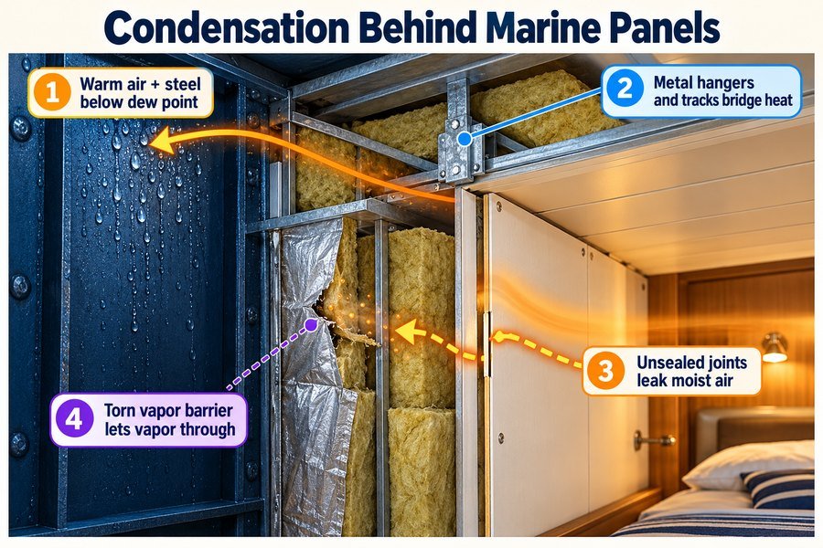
I have seen brand-new cruise ship and offshore vessel cabins develop black mold and brown rust streaks before sea trials even finish. Many interior contractors and procurement managers blame the panel manufacturer first. But the real problem usually sits in the hidden cavity between the ship hull and the interior lining. When warm, humid cabin air meets cold steel structures, liquid water forms out of thin air. If you buy marine wall panels, ceiling panels, and fire doors in Asia for European or American shipyard projects, you need to know the exact numbers and weak points that cause sweating panels.
What Temperature Difference Triggers Surface Condensation on Marine Interior Panels?
Sweating cabin walls ruin PVC finishes and stain ceiling tiles. Guessing temperature limits causes failed shipyard inspections. You need exact thermal numbers to specify the right interior panels.
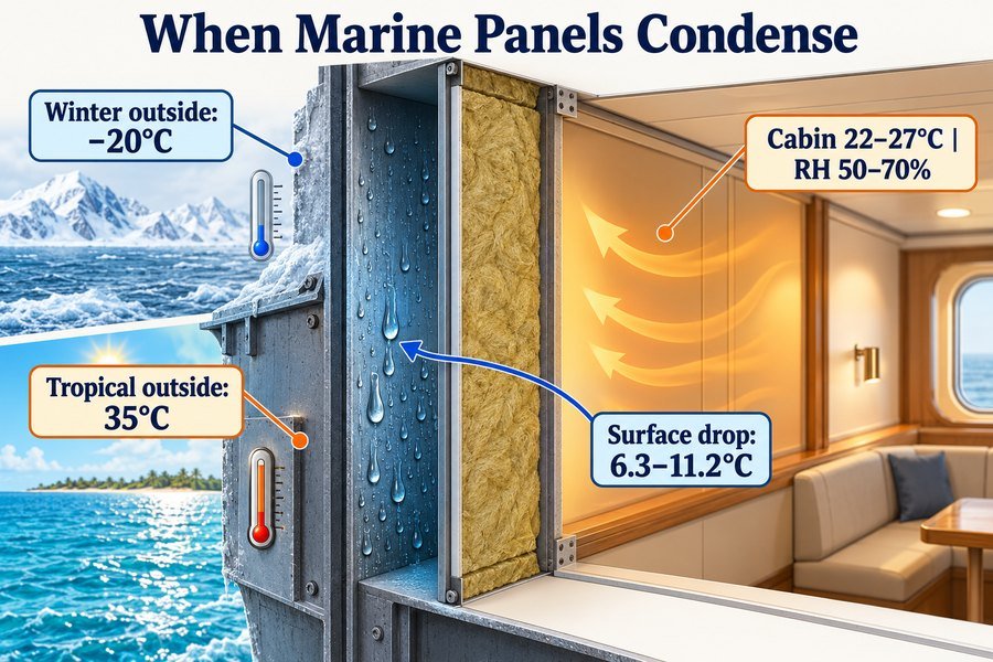
Under ISO 7547 cabin conditions of 22°C to 27°C and 50% to 70% relative humidity, surface condensation triggers when marine panel temperatures drop by 6.3°C to 11.2°C below ambient room air, which happens when outside temperatures reach -20°C in winter or 35°C in tropical summer waters.
Temperature Drops Under ISO 7547 Winter Heating Conditions
Shipbuilders design cabin HVAC systems using the ISO 7547 standard for air-conditioning and ventilation of accommodation spaces. Under ISO 7547 winter rules1, the outside air temperature sits at -20°C and seawater sits at 0°C. The indoor cabin temperature must stay at 22°C with a relative humidity of 50%. Under these winter settings, condensation triggers as soon as the marine wall panel surface temperature drops by 11.2°C. That means any panel surface or rear steel sheet at or below 10.8°C will collect liquid water.
I remember working on a cargo vessel accommodation block during my early factory days. The contractor bought standard 25mm B-0 rockwool wall panels at $19 per square meter to save money. They installed these panels near an poorly insulated external bulkhead in North Europe. The cold hull pulled the rear panel temperature down to 8°C. Within two weeks, water pooled inside the bottom floor tracks because the 11.2°C temperature drop threshold was crossed.
Temperature Drops Under ISO 7547 Tropical Cooling Conditions
Tropical voyages create an even tighter temperature margin for marine interior contractors. Under ISO 7547 summer rules, outside air reaches 35°C with 70% relative humidity, while seawater hits 32°C. The cooled cabin air stays at 27°C with 50% to 70% relative humidity depending on door openings and fresh air intake. When humid air at 27°C and 70% relative humidity enters the ceiling void or hits a cold panel, a temperature drop of just 6.3°C triggers surface condensation. Any steel surface at 20.7°C or lower will sweat immediately.
This issue often happens behind marine ceiling panels where chilled water pipes and cold HVAC supply ducts run at 12°C to 15°C. At Magellan Marine, I always advise buyers to check the thermal conductivity (K-value) of the panel core under EN 12667. A 50mm B-15 rockwool panel with a thermal conductivity of 0.038 W/m·K keeps the temperature drop under 3.5°C, which prevents panel sweating in both winter and tropical zones.
| Climate Zone (ISO 7547) | Outside Temp (°C) | Cabin Ambient Temp (°C) | Cabin Relative Humidity (%) | Critical Temp Drop Trigger (ΔT) | Dew Point Threshold (°C) | Minimum Recommended Panel Spec |
|---|---|---|---|---|---|---|
| Winter Navigation | -20°C Air / 0°C Sea | 22.0°C | 50% | 11.2°C drop | 10.8°C | 50mm B-15 Rockwool + 60mm Hull Insulation |
| Temperate Spring/Fall | 10°C Air / 10°C Sea | 22.0°C | 60% | 8.1°C drop | 13.9°C | 25mm to 50mm B-15 Rockwool Panel |
| Tropical Summer | 35°C Air / 32°C Sea | 27.0°C | 50% | 11.4°C drop | 15.6°C | 25mm B-15 Panel + Vapor Sealed Cavity |
| Tropical High Humidity | 35°C Air / 32°C Sea | 27.0°C | 70% | 6.3°C drop | 20.7°C | 50mm B-15 Panel + Sealed EPDM Joints |
How Does Dew Point Determine Condensation Risk on Marine Interior Panels?
Invisible water vapor hides in every ship cabin. When humidity spikes, dry bulkheads turn into wet sponges overnight. Mastering dew point math stops moisture damage before installation starts.
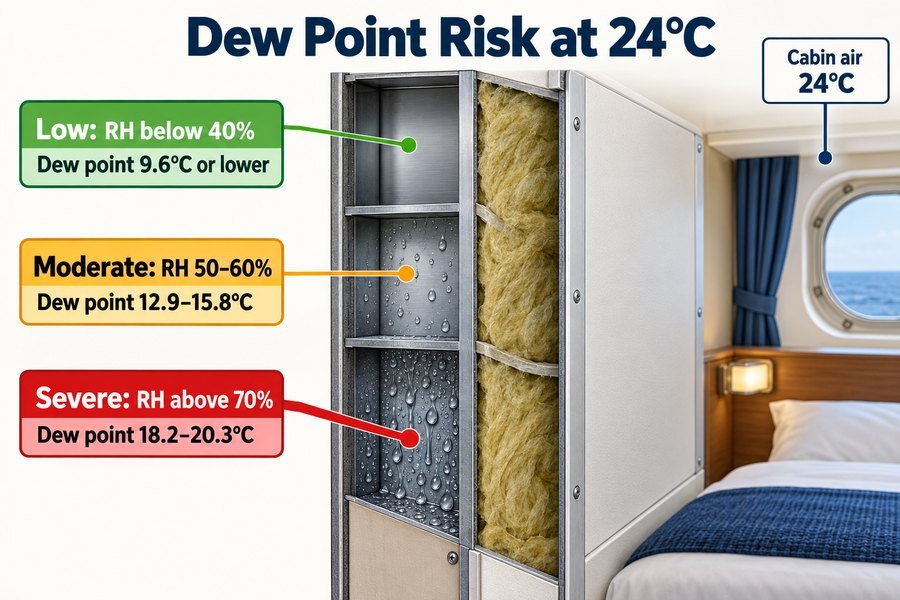
Dew point determines condensation risk across three relative humidity zones at a standard 24°C cabin temperature: low risk below 40% humidity (9.6°C dew point), moderate risk at 50% to 60% humidity (12.9°C to 15.8°C dew point), and severe risk above 70% humidity (18.2°C to 20.3°C dew point).
Low and Moderate Dew Point Zones in Standard Passenger Cabins
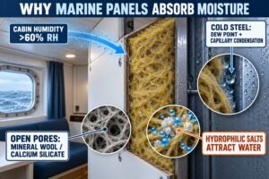
The dew point is the exact temperature where invisible water vapor in the air turns into liquid water droplets. According to ASHRAE Psychrometric Charts, the dew point depends on air temperature and relative humidity.2 Most modern cruise ships and offshore living quarters set their cabin thermostats to a comfortable 24°C baseline. When the ship HVAC system keeps cabin relative humidity in the low risk zone below 40%, the dew point sits at 9.6°C or lower. Under these dry conditions, the rear 0.6mm galvanized steel sheet of your marine wall panel stays completely dry unless the ship sails in freezing Arctic waters without enough hull insulation.
In most normal voyages, cabin humidity sits in the moderate risk zone between 50% and 60% relative humidity at 24°C. At 50% humidity, the dew point is 12.9°C. At 60% humidity, the dew point rises to 15.8°C.3 In this moderate zone, standard 25mm or 50mm marine lining panels perform well, provided the cavity air behind the panels stays isolated from cold steel frames and chilled water pipes.
Severe Dew Point Zones in Wet Spaces and Tropical Voyages
Condensation risk jumps into the severe zone when relative humidity rises above 70% at 24°C. At 70% relative humidity, the dew point reaches 18.2°C. At 80% relative humidity, the dew point hits 20.3°C. A panel surface only needs to be 3.7°C cooler than the room air to start dripping water. This severe zone happens every day in crew shower rooms, galleys, laundry rooms, and cabins where crew members prop open exterior doors in humid ports.
Two years ago, I helped an interior contractor who was outfitting an accommodation barge in Southeast Asia. The crew left weather deck doors open during humid 80% relative humidity days, while the cabin air conditioning blew 16°C cold air against the ceiling panels. Because 16°C is lower than the 20.3°C dew point, condensation formed inside the ceiling cavity and rusted the panel edges in three months. We solved the issue on their next vessel by supplying PVC-laminated wall and ceiling panels with an extra 10-micron epoxy back-coat and sealing the ceiling plenum to block humid outside air.
| Humidity Risk Zone | Cabin Air Temp (°C) | Relative Humidity (%) | Exact Dew Point (°C) | Max Allowable Temp Drop (°C) | Typical Shipboard Location | Required Panel Protection Level |
|---|---|---|---|---|---|---|
| Low Risk Zone | 24.0°C | 30% to 40% | 5.4°C to 9.6°C | 14.4°C to 18.6°C | Climate-controlled wheelhouse, dry offices | Standard Z120 galvanized steel panel |
| Moderate Risk Zone | 24.0°C | 50% to 60% | 12.9°C to 15.8°C | 8.2°C to 11.1°C | Standard crew and passenger sleeping cabins | Z120/Z180 panel + standard vapor barrier |
| Severe Risk Zone (70% RH) | 24.0°C | 70% | 18.2°C | 5.8°C | Corridors near weather deck doors, mess rooms | Z275 galvanized panel + EPDM joint seals |
| Severe Risk Zone (80% RH) | 24.0°C | 80% | 20.3°C | 3.7°C | Sanitary wet units, galleys, laundry spaces | Z275 or stainless steel panel + full silicone seal |
Which Marine Wall Panel Joints, Tracks, and Penetrations Risk Condensation Most?
Even top-grade insulated panels fail if warm air leaks behind them. Air gaps turn tiny metal joints into water traps. You must seal every weak boundary on the bulkhead.
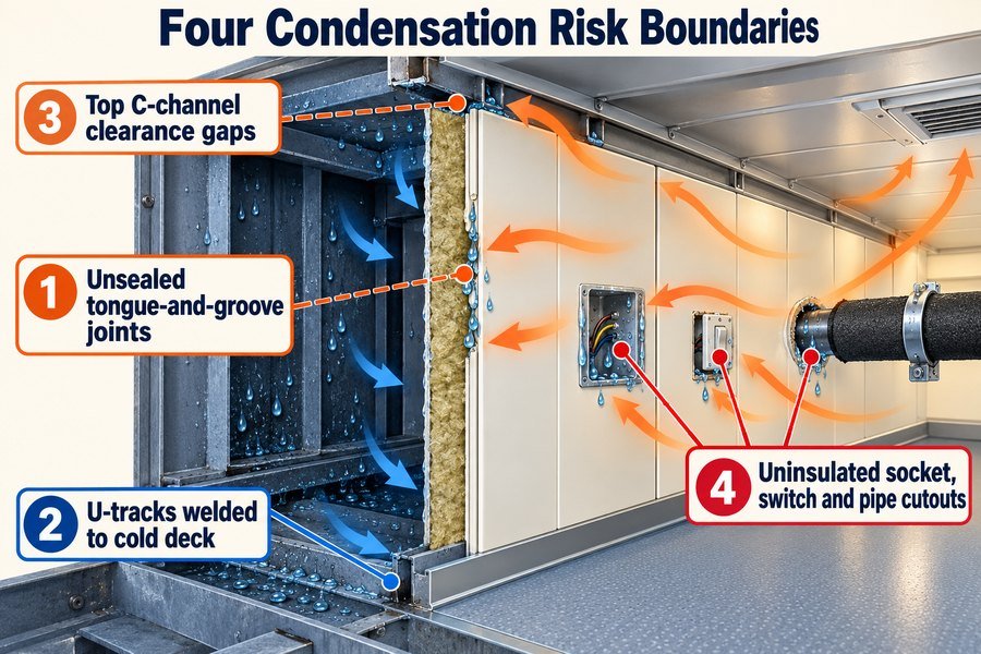
Four structural boundaries carry the highest condensation risk on marine wall panels: unsealed tongue-and-groove vertical panel joints, bottom U-tracks welded directly to steel decks, top ceiling C-channels with clearance gaps, and uninsulated cutouts for electrical sockets, light switches, and HVAC piping penetrations.
Air Leakage at Tongue-and-Groove Panel Joints and Top Ceiling C-Channels
Most condensation behind marine panels is driven by air movement, not simple heat transfer through the rockwool core. Under ISO 7547 ventilation rules, ship cabins maintain a slight positive air pressure of 15 Pa to 30 Pa compared to corridors and hidden voids. This pressure pushes warm, moist cabin air through any tiny gap in the wall system4. The first major leak path is unsealed tongue-and-groove vertical panel joints (or spline joints). During fast shipyard installation, workers often leave a 1mm to 2mm clearance gap between panels. Warm air flows straight through that vertical seam into the cold cavity behind the wall.
The second major air leak happens at top ceiling C-channels with clearance gaps. Installers usually cut wall panels 5mm to 10mm shorter than the ceiling height so they can tilt the panel into the top C-channel. If the installer does not apply an acoustic/vapor sealant bead along the top edge, warm air rises and pours through that 5mm gap into the cold steel deckhead space above the marine ceiling panels.
Thermal and Moisture Failure at Welded Bottom U-Tracks and Electrical Penetrations
The third high-risk boundary is the bottom U-track welded directly to the steel deck. Standard bottom tracks are made from 1.5mm to 2.0mm galvanized steel channels. When welders stitch-weld this track directly onto a cold steel deck plate, the U-track becomes a cold metal trough. Any moisture running down the back of the marine wall panel collects inside the U-track, where it rots the bottom edge of the rockwool core and causes bubbling beneath the decorative PVC film within 6 to 12 months.
The fourth danger zone covers uninsulated cutouts for electrical sockets, light switches, and HVAC piping penetrations5. When electricians cut a 70mm x 70mm hole into a B-15 wall panel to mount a cabin power socket, they pull out a handful of rockwool insulation to make room for the plastic back-box and cables. This leaves an open hole directly into the cold bulkhead cavity. At Magellan Marine, I tell our clients to spend an extra $0.80 per linear meter for closed-cell EPDM rubber gaskets inside panel joints and $1.50 per socket for intumescent acoustic putty pads that block both fire and moist air.
| High-Risk Boundary Location | Typical Dimensional Gap / Spec | Primary Condensation Mechanism | Field Failure Symptom | Recommended Engineering Fix & Cost |
|---|---|---|---|---|
| Tongue-and-Groove Vertical Joints | 1.0mm to 2.0mm assembly tolerance | Positive cabin pressure (15–30 Pa) pushes humid air into void | Rust streaks along vertical panel seams | Factory-fitted EPDM gasket ($0.60–$0.90/m) |
| Bottom Steel U-Tracks | 1.5mm to 2.0mm steel welded to deck | Direct deck thermal bridge + gravity water trap | Peeling PVC film and rusted panel bottom | 3mm PE thermal break tape + drainage holes ($0.50/m) |
| Top Ceiling C-Channels | 5.0mm to 10.0mm installation clearance | Rising warm air convects into cold deckhead void | Water dripping from ceiling edge profiles | Silicone sealant bead + mineral wool stuffing ($0.80/m) |
| Socket, Switch & Pipe Cutouts | 70mm x 70mm box hole / 50mm pipe hole | Removed rockwool core exposes cold rear cavity | Wet electrical boxes and short circuits | Putty pads + EPDM pipe grommets ($1.20–$2.00/each) |
How Do Steel Profiles and Hangers Trigger Condensation Behind Marine Interior Panels?
Metal framing holds your ship cabin together, but it also acts as a highway for cold energy. Uninsulated steel hangers drip water straight onto your new ceiling panels.
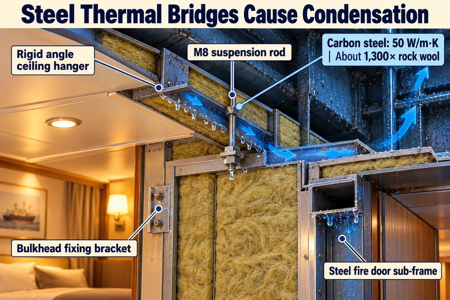
Steel profiles and hangers trigger condensation because carbon steel has a high thermal conductivity of 50 W/m·K—1,300 times higher than rockwool insulation—creating severe thermal bridges across four components: rigid angle steel ceiling hangers, M8 threaded suspension rods, bulkhead fixing brackets, and steel fire door sub-frames.
Thermal Bridging Physics Across Rigid Angle Hangers and M8 Suspension Rods
To understand why metal hardware ruins marine ceilings, you only need to look at thermal conductivity values in ISO 10211 (Thermal bridges in building and marine construction)6. Standard carbon steel has a thermal conductivity of 50 W/m·K. In contrast, marine rockwool insulation has a thermal conductivity of 0.038 W/m·K. That means steel conducts heat and cold 1,300 times faster than rockwool insulation7.
When shipyards suspend marine ceiling panels, they use two main hardware styles: rigid angle steel ceiling hangers (typically 30mm x 30mm x 3mm L-angles welded to deckhead frames) or M8 threaded suspension rods with turnbuckles for lighter B-0/B-15 ceilings. These metal hangers punch directly through the hull insulation to weld onto the structural steel deckhead. If the exterior steel deck sits at 0°C, heat flows rapidly up the steel hanger. Even 300mm below the deckhead, the bottom tip of an uninsulated angle steel hanger or M8 rod sits at 8°C to 11°C8. Since normal cabin air has a dew point of 13°C to 15°C, water droplets form all over the steel hanger and drip onto the back of your marine ceiling panels.
Heat Loss Through Bulkhead Fixing Brackets and Steel Fire Door Sub-Frames
The exact same thermal bridging problem happens horizontally on walls. Installers secure marine wall panels to the ship structure using steel bulkhead fixing brackets spaced every 600mm to 1,200mm vertically. When these steel brackets bolt directly from a cold structural stiffener to the rear C-profile of a wall panel, they create cold spots right on the panel seam.
Even worse are steel fire door sub-frames. A-60 and B-15 marine fire doors use heavy 1.5mm to 3.0mm thick painted or stainless steel frames that bolt or weld directly to the steel bulkhead opening. If the contractor forgets to pack mineral wool into the hollow door frame cavity or omits a thermal break gasket, the entire door frame sweats water onto the cabin carpet. On a project I supported for a European shipyard client, we added 5mm neoprene thermal break pads on all bulkhead brackets and wrapped the top 150mm of every ceiling hanger with 13mm closed-cell nitrile rubber insulation. That simple step cost less than $1.10 per hanger and eliminated ceiling water stains completely.
| Steel Framing Component | Typical Material & Size | Thermal Conductivity (ISO 10211) | Uninsulated Surface Temp (at 0°C Hull) | Condensation Prevention Method |
|---|---|---|---|---|
| Rigid Angle Ceiling Hangers | Carbon steel L-angle, 30x30x3mm | 50.0 W/m·K | 8.5°C to 10.5°C | Wrap top 150mm with 13mm nitrile rubber foam |
| M8 Threaded Suspension Rods | Galvanized steel rod, 8mm diameter | 50.0 W/m·K | 9.5°C to 11.5°C | Use rubber isolator bushings at ceiling C-carrier |
| Bulkhead Fixing Brackets | Slotted steel bracket, 2.0mm thick | 50.0 W/m·K | 9.0°C to 11.0°C | Install 5mm neoprene or polyamide thermal break pad |
| Steel Fire Door Sub-Frames | Pressed steel Z-frame, 1.5mm–3.0mm | 50.0 W/m·K | 7.0°C to 10.0°C | Pack frame hollow with 140 kg/m³ rockwool + gasket |
How Do Breached Hull Vapor Barriers Cause Condensation Behind Marine Lining Panels?
One torn foil layer on the hull turns mineral wool into a soggy sponge. Water drips into your cabin panels for years. You must protect the vapor barrier during outfitting.
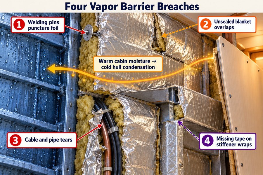
Breached hull vapor barriers cause condensation through four installation defects: welding pins puncturing aluminum foil facing, unsealed overlaps between mineral wool blankets, tears from dragging cables and pipes, and missing foil tape at steel stiffener wraps, letting warm cabin moisture condense on the cold hull.
Vapor Diffusion Through Punctured Aluminum Foil and Unsealed Blanket Overlaps
Before your crew installs decorative marine wall panels, the shipyard covers the steel hull and deckheads with A-60 or thermal mineral wool blankets faced with reinforced aluminum foil. This foil layer is not for decoration; it is the primary vapor barrier. Under ASTM E96 and ISO 12572 testing, intact 30-micron to 50-micron reinforced aluminum foil has a water vapor permeance below 0.02 perms (1.1 ng/Pa·s·m²)9, which blocks almost 100% of moisture diffusion. However, mineral wool behind the foil is completely open to air and vapor10.
The first defect happens when insulation workers impale mineral wool blankets onto 3mm steel welding pins (spaced every 300mm on the hull) and secure them with spring steel speed-clips. Every pin punches a hole in the aluminum foil facing. If workers do not cover every speed-clip with a self-adhesive aluminum foil patch, dozens of vapor leaks open up on every square meter of bulkhead11. The second defect is unsealed overlaps between mineral wool blankets. Blankets must overlap by at least 50mm and be sealed tight. When workers leave loose, unsealed seams, warm cabin humidity passes right between the blankets, hits the cold steel hull behind the wool, and condenses into water.
Moisture Intrusion From Cable Dragging Tears and Unwrapped Steel Stiffeners
The third defect happens after the insulation team leaves the cabin. Electricians and pipefitters work in the narrow space between the hull and the wall framing, and they often create tears from dragging cables and pipes across the aluminum foil facing. A single 100mm tear lets liters of water vapor enter the mineral wool over a winter voyage.
The fourth defect is missing foil tape at steel stiffener wraps. Ship hulls have deep T-bar or bulb-flat steel stiffeners every 600mm to 800mm. Wrapping wool around these complex steel shapes leaves corner joints that quickly pop open if workers skip applying 75mm-wide MED-certified aluminum foil tape. Once hull mineral wool absorbs just 5% moisture by weight, its thermal conductivity doubles from 0.036 W/m·K to over 0.072 W/m·K12. The wet wool loses its insulating power, grows heavy, sags against the back of your marine lining panels, and rusts them from behind. During a site audit I did in China, we required the yard to spend $15 per roll on 75mm MED-approved acrylic-adhesive aluminum tape to patch all pins and stiffeners before closing the walls. That $300 tape investment saved over $12,000 in replacement wall panels.
| Vapor Barrier Defect | Root Cause During Outfitting | Permeance / Moisture Impact (ASTM E96) | Secondary Damage to Marine Panels | Mandatory Quality Check Before Panel Closure |
|---|---|---|---|---|
| Welding Pin Punctures | 3mm pins & speed-clips left uncovered (6–9 pins/m²) | Increases vapor leak rate by 300% to 500% | Rust spots on hull bleeding onto bottom panel tracks | Cover 100% of clips with 100x100mm foil patches |
| Unsealed Blanket Overlaps | Missing 50mm seam overlap or peeled tape | Direct convective vapor bypass to cold hull plate | Soggy wool sags against rear face of wall panels | Enforce 50mm overlap + 75mm wide MED foil tape |
| Cable & Pipe Dragging Tears | Heavy armored cables pulled against foil facing | Rapid localized saturation (wool >5% moisture by weight) | Wet wool doubles K-value (0.072 W/m·K), cooling panel | Patch all tears >10mm with reinforced foil tape |
| Unsealed Stiffener Wraps | Foil tension pulls seams open on T-bar stiffener corners | Cold steel stiffener sweats directly into cabin void | Water drips from stiffener onto ceiling panels | Wrap stiffeners fully and tape all corner miters |
How Is Shipboard Condensation Risk Addressed in Marine Interior Panel Specifications?
Buying cheap panels without clear moisture specs ruins your profit margin on shipyard contracts. Vague purchase orders invite disputes. You can protect your budget with strict technical specifications.
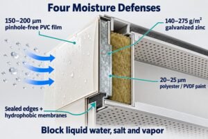
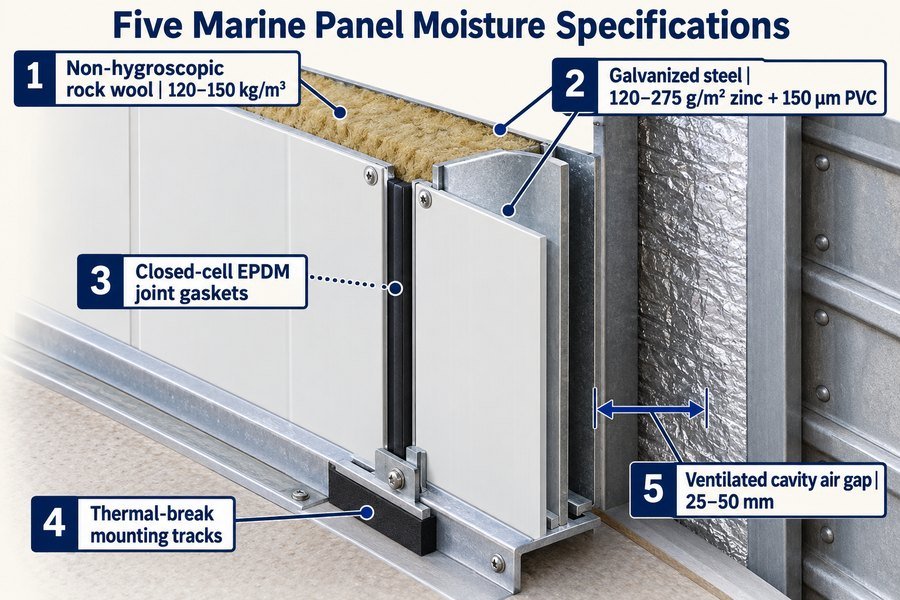
Marine interior panel specifications prevent condensation through five technical requirements: non-hygroscopic rockwool cores (120 to 150 kg/m³ density), galvanized steel sheets (120 to 275 g/m² zinc coating) with 150-micron PVC film, closed-cell EPDM joint gaskets, thermal break mounting tracks, and 25mm to 50mm ventilated cavity air gaps.
Core Density and Galvanized Steel Coating Standards for Moisture Resistance
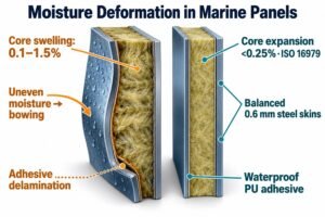
As a procurement officer sourcing marine interior panels from China or Vietnam for European and American shipyards, you may not have time to calculate dew points for every cabin. Instead, you can eliminate condensation callbacks by putting five exact technical lines into your purchase contract. First, specify non-hygroscopic rockwool cores with a density of 120 to 150 kg/m³ for wall panels (and 100 to 120 kg/m³ for ceiling panels), certified under the IMO 2010 FTP Code13. You must require water-repellent rockwool tested to EN 1609 with short-term water absorption below 1.0 kg/m². If moisture ever enters the cavity, non-hygroscopic rockwool sheds the water14 instead of soaking it up like a sponge.
Second, specify the exact steel skin protection. Low-cost domestic factories often use thin electro-galvanized steel with only 20 to 40 g/m² of zinc, which rusts in weeks when damp. Your specification must require hot-dip galvanized steel sheets (0.5mm to 0.7mm thick) with 120 to 275 g/m² zinc coating (EN 10346 Grade Z120 to Z275), laminated with a 150-micron decorative PVC film on the visible side and a 7-micron to 10-micron anti-corrosion epoxy primer on the hidden rear side. At Magellan Marine, upgrading a 25mm B-15 wall panel from Z120 to Z275 zinc coating only increases the FOB price from $23.50/m² to $25.80/m², and it does not add a single day to our standard 20-day production lead time.
Specifying EPDM Joint Gaskets, Thermal Break Tracks, and Cavity Ventilation
Third, require factory-installed closed-cell EPDM joint gaskets along the vertical tongue-and-groove or M-profile joints. These gaskets stop humid cabin air from leaking behind the panels and boost sound insulation by 2 to 3 dB15 at the same time. Fourth, specify thermal break mounting tracks. Ask your supplier to pre-apply a 3mm closed-cell polyethylene or neoprene foam strip to the underside of all bottom steel U-tracks and bulkhead brackets so installers do not have to source tape at the shipyard.
Fifth, ensure your installation drawings call for 25mm to 50mm ventilated cavity air gaps between the aluminum foil face of the hull insulation and the rear steel face of the marine wall panel, in line with IACS and shipyard accommodation standards. This air gap stops wet hull wool from touching your panel and keeps temperatures balanced. When you put these five numbers into your inquiry, Asian suppliers know immediately that you understand marine engineering, and you get European-grade quality at competitive Asian prices.
| Specification Item | Standard Low-Cost Market Spec | Recommended Condensation-Proof Spec | Authoritative Standard / Rule | FOB Price Impact (USD / m²) |
|---|---|---|---|---|
| Rockwool Core Density & Type | 80–100 kg/m³, untreated wool | 120–150 kg/m³, non-hygroscopic (<1.0 kg/m² absorption) | IMO 2010 FTP Code / EN 1609 | +$1.20 to +$1.80 / m² |
| Steel Sheet Zinc Coating | Electro-galvanized (20–40 g/m² zinc) | Hot-dip galvanized Z120 to Z275 (120–275 g/m² zinc) | EN 10346 | +$1.50 to +$2.30 / m² |
| Surface & Rear Film Coating | 100-micron PVC / bare steel back | 150-micron IMO PVC front / 10-micron epoxy rear coat | IMO FTPC Part 5 & Part 2 | +$0.80 to +$1.20 / m² |
| Panel Joint Sealing | Bare metal-to-metal tongue & groove | Pre-fitted closed-cell EPDM joint gasket strip | ISO 7547 air tightness practice | +$0.60 to +$0.90 / m² |
| Track & Cavity Isolation | Direct welded U-track, 0mm gap | 3mm PE thermal break track + 25mm–50mm air gap | ISO 10211 / Shipyard standards | +$0.50 / m² |
Conclusion
Stopping condensation behind marine panels requires controlling cabin dew points, sealing panel joints, insulating steel hangers, protecting hull vapor barriers, and specifying Z120-Z275 galvanized rockwool panels with thermal breaks.
-
"Thermal Comfort Studies", https://www.nist.gov/el/net-zero-energy-residential-test-facility/thermal-comfort-studies. ISO 7547 specifies design conditions for ship accommodation HVAC systems, including winter outside-air, seawater, indoor temperature, and humidity assumptions used for heat-load calculations. Evidence role: definition; source type: institution. Supports: Under ISO 7547 winter rules, the outside air temperature is -20°C, seawater is 0°C, and indoor cabin conditions are 22°C at 50% relative humidity.. Scope note: The source supports the standardized design assumptions, not the article’s subsequent condensation calculations or field example. ↩
-
"CDL.Psychrometrics", https://obc.lbl.gov/specification/cdl/latest/help/CDL_Psychrometrics.html. ASHRAE psychrometric materials show that dew-point temperature is derived from the thermodynamic state of moist air, including dry-bulb temperature and humidity measures such as relative humidity. Evidence role: definition; source type: institution. Supports: Dew point depends on air temperature and relative humidity as represented in ASHRAE psychrometric charts.. Scope note: This supports the psychrometric relationship generally; exact values still depend on the pressure and formula or chart used. ↩
-
"Psychrometric Calculator", https://people.tamu.edu/~i-choudhury/psych.html. Psychrometric calculations for air at 24°C give dew-point temperatures of approximately 12.9°C at 50% relative humidity and 15.8°C at 60% relative humidity, supporting the numerical examples used for the moderate-humidity zone. Evidence role: statistic; source type: education. Supports: At 24°C, 50% and 60% relative humidity correspond to dew points of about 12.9°C and 15.8°C, respectively.. Scope note: The values are approximate and may vary slightly with barometric pressure, rounding method, or psychrometric equation. ↩
-
"Review of Air Barrier Issues", https://web.ornl.gov/sci/buildings/conf-archive/2004%20B9%20papers/091_Bomberg.pdf. Fluid-flow models for building and enclosure leakage show that pressure differences drive airflow through cracks and small openings, providing a physical basis for moisture-bearing air movement through panel joints. Evidence role: mechanism; source type: paper. Supports: Small gaps in a wall system can allow pressure-driven leakage of warm, humid air into hidden cavities.. Scope note: Such models establish the general pressure-leakage mechanism but do not quantify leakage for the specific marine tongue-and-groove joint dimensions in the article. ↩
-
"How to choose the right marine wall panels for marine interior ...", https://magellanmarinetech.com/how-choose-right-marine-wall-panels-for-marine-interior-projects/. Firestopping and building-envelope guidance treats service penetrations as locations requiring sealing or insulation continuity because openings can compromise fire, acoustic, air-leakage, and thermal performance of a rated assembly. Evidence role: expert_consensus; source type: institution. Supports: Uninsulated service penetrations such as sockets, switches, and pipe cutouts are high-risk locations for air leakage, thermal discontinuity, and performance loss in wall assemblies.. Scope note: The support is general to rated wall and envelope penetrations; a ship-classification or marine fire-test source would be needed to confirm requirements for a specific B-15 marine panel system. ↩
-
"An AI-based approach to thermal bridge analysis - PMC", https://pmc.ncbi.nlm.nih.gov/articles/PMC12378188/. ISO 10211 specifies numerical methods for calculating heat flows and surface temperatures at thermal bridges in building construction, supporting its use as a thermal-bridge calculation reference. Evidence role: definition; source type: institution. Supports: ISO 10211 is relevant to the analysis of thermal bridges and surface temperatures.. Scope note: The standard supports thermal-bridge methodology, but it may not directly provide the article’s material-property values or marine-specific installation details. ↩
-
"Thermal Conductivity", http://hyperphysics.phy-astr.gsu.edu/hbase/Tables/thrcn.html. Published material-property references list steel thermal conductivity at roughly 45–60 W/m·K and mineral or rock wool insulation around 0.035–0.045 W/m·K, which supports an order-of-magnitude conductivity ratio of about 1,000–1,500. Evidence role: statistic; source type: education. Supports: Steel has a thermal conductivity roughly 1,300 times higher than rockwool insulation.. Scope note: Exact values vary with steel alloy, insulation density, temperature, moisture content, and test method. ↩
-
"Thermal Bridges", https://web.ornl.gov/sci/buildings/2016/docs/presentations/workshops/workshop-3/Workshop3_Bossche.pdf. Finite-element and standard thermal-bridge analyses show that conductive steel penetrations through insulation can significantly depress interior surface temperatures near the penetration under cold-side boundary conditions. Evidence role: case_reference; source type: paper. Supports: An uninsulated steel hanger or M8 rod connected to a 0°C deckhead can have a cold exposed tip in the approximate 8–11°C range.. Scope note: Such sources would contextualize the temperature range; direct proof of 8–11°C requires a calculation or test using the article’s exact hanger geometry, insulation thickness, and boundary conditions. ↩
-
"Permeability of Common Building Material to Water Vapor", https://www.uaf.edu/ces/publications/database/energy/permeability-water-vapor.php. The source reports water-vapor permeance or resistance values for aluminum foil or foil-faced vapor barriers under ASTM E96, ISO 12572, or equivalent methods, supporting the statement that intact foil has very low vapor permeance. Evidence role: statistic; source type: paper. Supports: Intact 30-micron to 50-micron reinforced aluminum foil has water vapor permeance below 0.02 perms.. Scope note: The source may support the material property of intact foil but not the installed performance of punctured or damaged foil facings. ↩
-
"Moisture Durability with Vapor-Permeable Insulating Sheathing", https://docs.nlr.gov/docs/fy14osti/58062.pdf. The source explains that mineral wool insulation is vapor-permeable and does not function as an air or vapor barrier, supporting the distinction between the foil facing and the fibrous insulation core. Evidence role: definition; source type: institution. Supports: Mineral wool behind the foil is open to air and vapor compared with the foil vapor barrier.. Scope note: The source is likely to describe mineral wool as highly vapor-permeable in general; exact permeability varies by density, binder, facing, and installation condition. ↩
-
"JOTS v37n2 - Impact of Climate and Geographic Location on ...", https://scholar.lib.vt.edu/ejournals/JOTS/v37/v37n2/larson.html. The source documents that penetrations, fasteners, or punctures in vapor-retarder membranes can substantially increase vapor transport through an otherwise low-permeance layer, supporting the mechanism by which uncovered pins create multiple leakage paths. Evidence role: mechanism; source type: research. Supports: Uncovered welding-pin punctures create many vapor leakage paths through the foil facing on each square meter of bulkhead.. Scope note: The source may support the general effect of membrane penetrations rather than the exact number of leaks per square meter in a shipboard installation. ↩
-
"Determination of Thermal Properties of Mineral Wool ... - PMC", https://pmc.ncbi.nlm.nih.gov/articles/PMC10488771/. The source reports the relationship between moisture content and thermal conductivity in mineral wool or fibrous insulation, supporting the claim that absorbed moisture significantly degrades insulating performance. Evidence role: statistic; source type: paper. Supports: Mineral wool with about 5% moisture by weight can experience a large increase, potentially doubling, in thermal conductivity from approximately 0.036 W/m·K to above 0.072 W/m·K.. Scope note: The exact doubling at 5% moisture by weight may depend on mineral-wool density, test temperature, moisture distribution, and measurement method. ↩
-
"What Is the Purpose and Scope of the IMO FTP Code?", https://magellanmarinetech.com/what-purpose-scope-of-imo-ftp-code/. The IMO 2010 FTP Code sets fire test procedures used under SOLAS for shipboard materials and products, including tests relevant to non-combustibility and surface flammability of accommodation materials; it supports the regulatory context but does not prescribe rockwool density ranges. Evidence role: historical_context; source type: institution. Supports: Marine interior panel cores should be certified under the IMO 2010 FTP Code.. Scope note: Supports the maritime fire-testing framework, not the specified 120–150 kg/m³ density requirement. ↩
-
"Water adsorption on surfaces of calcium aluminosilicate ...", https://pmc.ncbi.nlm.nih.gov/articles/PMC11033287/. Research and technical literature on mineral wool insulation describe how hydrophobic treatment and fiber structure can reduce liquid-water uptake and capillary transport; this supports the general mechanism but does not prove that every rockwool product marketed as non-hygroscopic will shed water under all installation conditions. Evidence role: mechanism; source type: paper. Supports: Treated non-hygroscopic rockwool is less prone to retaining liquid water than absorbent insulation materials.. Scope note: Contextual support only; product-specific water repellency still depends on formulation, facing, aging, and installation conditions. ↩
-
"Airborne sound insulation performance of lightweight double ...", https://pmc.ncbi.nlm.nih.gov/articles/PMC11666719/. Building-acoustics research shows that gaps and air leakage through joints can reduce sound transmission loss and that sealing joints can improve measured sound insulation; this supports the mechanism, but the stated 2–3 dB gain would need panel-specific laboratory test data for direct verification. Evidence role: mechanism; source type: paper. Supports: Sealing panel joints with gaskets can improve sound insulation by reducing air leakage.. Scope note: Contextual support only; the exact dB improvement depends on panel geometry, gasket compression, frequency range, and test method. ↩