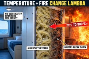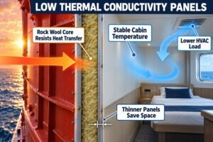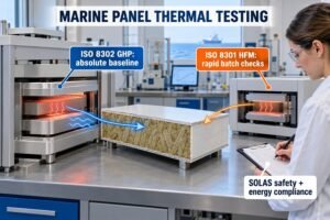
Ship fires destroy lives and cargo. Knowing how fast heat moves through a bulkhead panel is a major safety issue. This helps you select the right interior panels.
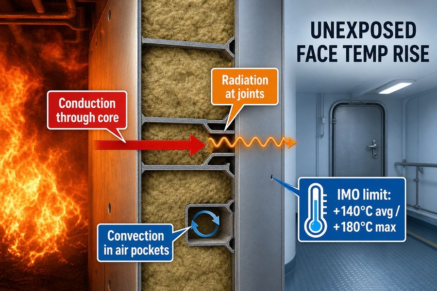
During a ship fire, temperature rises on the unexposed face through conduction across the core, radiation through panel joints, and convection via internal air pockets. The IMO limits this rise to 140°C average or 180°C maximum above ambient to ensure safe evacuation and prevent secondary ignition.
If you only need a quick summary of heat transfer basics for panel purchasing, you can stop reading here. But if you want to know how specific materials block this heat to save costs and meet safety codes, keep reading.
What Core Properties Delay Cold-Side Temperature Rise in Marine Wall Panels?
Choosing wrong panel materials causes failed inspections. I have seen buyers waste money on useless panels. You need to know exactly which core properties block heat transfer effectively.
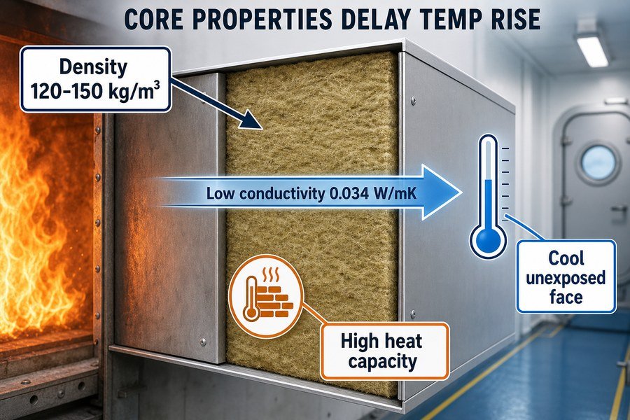
Three main core properties delay cold-side temperature rise: high density (typically 120-150 kg/m³ for rock wool), low thermal conductivity (around 0.034 W/mK), and high specific heat capacity. Together, these three factors slow down heat conduction and keep the unexposed face cool.
High Density in Rock Wool Cores Slows Heat
I always tell buyers that density is the most important factor for marine wall panels. According to the IMO FTP Code Part 3, standard rock wool density should be between 120 and 150 kg/m³ for A-60 class panels1. Density means more mass. When a fire hits a panel, more mass takes much longer to heat up2.
I remember a project where a buyer purchased cheap panels from a small factory in Asia. The factory used 80 kg/m³ rock wool to lower the price. The panel failed the A-60 fire test at the 40-minute mark. The heat passed right through the thin material. The cold side got too hot, and the European shipyard rejected the entire batch. You must always verify the density before you pay the supplier.
Low Thermal Conductivity and High Specific Heat Capacity in Panel Materials
High density alone is not enough. The core must also have low thermal conductivity. Good marine-grade rock wool has a thermal conductivity of about 0.034 W/mK at room temperature3. This very low number means the material naturally stops heat from flowing through it.
Next, we must look at specific heat capacity. This metric measures how much heat energy the core can absorb before its own temperature goes up. Marine rock wool has a specific heat capacity of about 0.84 kJ/kgK4. These two properties work together closely. They absorb the fire's energy and block heat from reaching the unexposed face of the panel. When you purchase panels for strict European shipyards, you must check the lab test reports for these exact three numbers.
| Core Property | Typical Marine Value | Function During a Fire Test |
|---|---|---|
| Density | 120 - 150 kg/m³ | Adds mass to slow down physical heating. |
| Thermal Conductivity | 0.034 W/mK | Stops heat from flowing from hot to cold side. |
| Specific Heat Capacity | 0.84 kJ/kgK | Absorbs heat energy before temperature rises. |
By checking high density, low thermal conductivity, and high specific heat capacity, you ensure the panel will pass inspections. I never buy a panel without verifying all three properties first.
How Does Localized Core Melting Create Hot Spots on a Marine Ceiling Panel?
Hot spots fail your IMO fire tests instantly. This causes huge project delays. Understanding why panels melt locally helps you inspect products before shipping them to the shipyard.
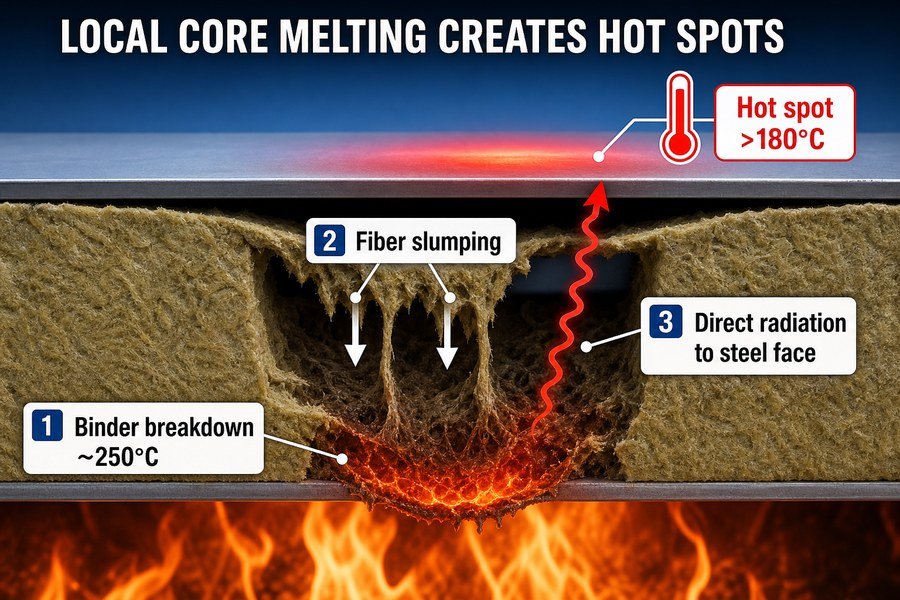
Localized core melting creates hot spots through three stages: binder resin breakdown around 250°C, fiber slumping leaving air gaps, and direct heat radiation hitting the steel face. These three actions ruin panel integrity, creating localized areas exceeding the 180°C maximum limit.
Binder Resin Breakdown at 250°C in Marine Ceiling Panels
The first stage of a hot spot starts with the binder resin. Factories use phenolic resin binders to glue rock wool fibers together. This keeps the core solid. However, this binder breaks down and burns away when the internal temperature reaches about 250°C5.
I have watched many fire tests in the lab. At 250°C, you can actually smell the resin burning off. Once the resin is gone, the rock wool fibers are loose. They have no glue holding them together. This is a very dangerous moment for a ceiling panel. If a factory uses cheap resin, it burns away even faster at 200°C. This ruins the panel early in the test.
Fiber Slumping and Direct Heat Radiation in Ceiling Cores
After the resin burns away, the second stage happens. Gravity pulls the loose rock wool fibers down. This is called fiber slumping. Because a ceiling panel hangs flat, the slumping fibers fall toward the hot side. This leaves an empty air gap near the cold-side steel plate.
The third stage happens immediately after the gap forms. Fire heat radiates directly through this empty air space. The heat hits the unexposed steel face plate directly. The steel gets hot instantly. According to IMO FTP Code Part 3, if any single point on the unexposed face gets hotter than 180°C above the room temperature, the panel fails6. This is exactly how a hot spot forms.
| Melting Stage | Temperature Range | Physical Effect on Ceiling Panel |
|---|---|---|
| 1. Binder Breakdown | 200°C - 250°C | Glue holding fibers together burns away. |
| 2. Fiber Slumping | > 250°C | Loose fibers fall down, creating empty air gaps. |
| 3. Direct Radiation | > 300°C | Heat hits the cold-side steel, causing hot spots. |
These three stages destroy the ceiling panel from the inside out. You must buy panels with high-quality, high-temperature resin to stop this chain reaction.
How Does the IMO Curve Dictate Marine Interior Panel Heat Saturation?
Failing to follow the IMO fire curve leads to rejected panels. This wastes your procurement budget. You must understand how this curve tests your panel's heat saturation limit.
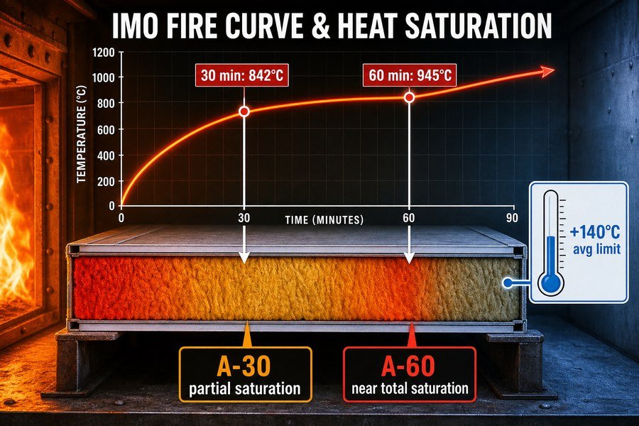
The IMO standard fire curve dictates heat saturation by forcing panels to withstand 842°C at 30 minutes and 945°C at 60 minutes. This rapid, continuous two-step temperature increase tests the panel's ability to resist total heat saturation over specific A-30 and A-60 timeframes.
Panel Heat Saturation During the 842°C at 30 Minutes Stage
The IMO FTP Code uses the ISO 834 standard fire curve. This curve is very aggressive. In the first 30 minutes, the furnace temperature rises rapidly to 842°C. I always tell my clients that this first stage is brutal. An A-30 marine panel must survive this exact time and temperature.
During these 30 minutes, heat slowly pushes into the rock wool core. The outer layers get hot, but the inner layers try to stay cool. This is the start of heat saturation. If the panel is poorly made, the core absorbs too much heat too fast. The heat reaches the cold side before 30 minutes. The panel fails its A-30 rating.
Extreme Heat Saturation at the 945°C at 60 Minutes Stage
If the panel is tested for an A-60 rating, it must stay in the furnace for 60 minutes. At this point, the IMO curve pushes the furnace temperature to 945°C. This is the second step. At this extreme temperature, the entire rock wool core is fighting total heat saturation.
Total saturation means the core can no longer hold any more heat energy. The core is full. Once it is full, it pushes all the new heat directly to the unexposed face. The cold side temperature will shoot up past the 140°C average limit7. Good panels delay this total saturation until exactly after 60 minutes.
| IMO Test Time | Furnace Temperature | Saturation Status for Panels |
|---|---|---|
| 0 Minutes | 20°C (Ambient) | No heat saturation. |
| 30 Minutes | 842°C | Partial saturation (Tests A-30 panels). |
| 60 Minutes | 945°C | Near total saturation (Tests A-60 panels). |
You must ensure your suppliers have official test reports showing they passed these two exact time and temperature steps. This proves the panel handles heat saturation properly.
What Material Failure Triggers a Thermal Breakthrough in a Marine Ceiling Panel?
A sudden temperature spike ruins a fire test. This means your supplier cut corners. Knowing the exact material failures helps you hold your suppliers accountable for quality.
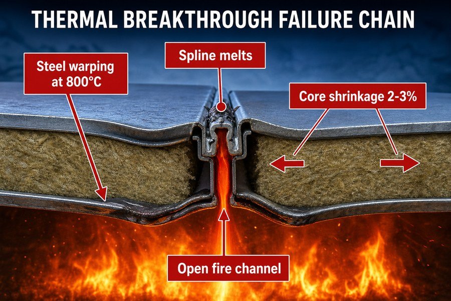
Thermal breakthrough in marine ceiling panels is triggered by three failures: steel face plate warping from thermal expansion, internal joint spline melting, and core fiber shrinkage. These three failures create open channels for fire, bypassing the insulation completely.
Steel Face Plate Warping and Joint Spline Melting in Ceiling Panels
Thermal breakthrough means the fire completely defeats the panel. The first failure that causes this is steel face plate warping. At 800°C, normal galvanized steel expands greatly.8 Because ceiling panels are bolted tightly to the ship's deck, the expanding steel has nowhere to go. The steel buckles and warps, pulling the panel joints apart.
The second failure happens right after. When the joints pull apart, the internal joint splines are exposed to direct fire. These splines connect the panels. If the factory used thin metal or cheap plastic splines, they melt instantly. I saw a cheap ceiling panel fail in 15 minutes because the spline melted. This opened a huge gap between the panels.
Core Fiber Shrinkage Leading to Complete Thermal Breakthrough
The third failure is core fiber shrinkage. Even good rock wool shrinks when it gets too hot. At 900°C, a standard rock wool core will shrink by about 2% to 3%.9 In a 2-meter long panel, a 3% shrinkage creates a 60mm gap inside the panel.
When the steel warps, the spline melts, and the core shrinks, you have a complete thermal breakthrough. Fire and hot gases flow directly through the open gaps to the unexposed side. The insulation does nothing. To stop this, high-quality panels use ceramic splines and expansion joints. These parts absorb the stress and keep the fire out.
| Failure Type | Cause of Failure | Resulting Damage to Ceiling Panel |
|---|---|---|
| Steel Warping | Thermal expansion at 800°C. | Pulls panel joints open forcefully. |
| Spline Melting | Direct fire exposure on cheap material. | Destroys the connection between two panels. |
| Fiber Shrinkage | Extreme heat at 900°C. | Creates large internal empty gaps. |
By understanding face plate warping, spline melting, and fiber shrinkage, you can inspect the supplier's structural drawings. Always look for strong splines and proper expansion gaps.
Is Thickness the Only Way to Delay Temperature Rise in Marine Wall Panels?
Many buyers think thicker panels are always better. This is a costly mistake. You can save money and space by using smart materials instead of just adding thickness.
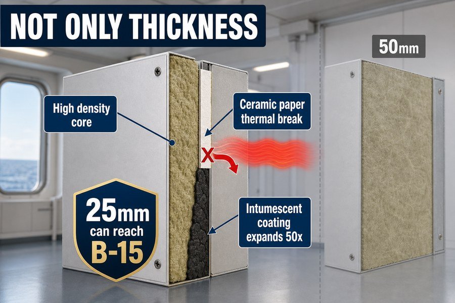
Thickness is not the only way; temperature rise is also delayed by three alternative methods: increasing core density, using ceramic paper thermal breaks, and applying intumescent coatings. These three methods allow a thinner 25mm panel to achieve B-15 ratings just like a thicker 50mm panel.
Increasing Core Density and Using Ceramic Paper Thermal Breaks
Shipyards in Europe hate losing cabin space. A 50mm panel takes up twice as much space as a 25mm panel. You do not need to rely on thickness. The first alternative method is increasing core density. A 25mm panel packed with 150 kg/m³ rock wool will block heat much better than a 50mm panel with only 80 kg/m³ rock wool. Density does the hard work.
The second method is using ceramic paper thermal breaks. Heat travels very fast through the steel edges of a panel joint.10 By adding a 1mm or 2mm layer of ceramic fiber paper inside the joint profile, you cut off the heat path. This thin paper acts as a wall. It stops the heat cold.
Applying Intumescent Coatings on Marine Wall Panels
The third method is applying intumescent coatings inside the panel. Factories paint this special coating on the inside of the steel plates. When the temperature hits 200°C, the intumescent paint reacts. It swells and expands up to 50 times its original thickness.
This expansion creates a thick, black carbon char layer. This char is an amazing insulator. I highly recommend buying panels that use this technology. By combining high density, ceramic paper breaks, and intumescent paint, a thin 25mm panel easily passes the B-15 fire test. You save space, shipping costs, and money, making your European shipyard clients very happy.
| Method to Delay Heat | How It Works | Typical Application |
|---|---|---|
| Increase Density | Adds mass without adding thickness. | 25mm B-15 cabin partitions. |
| Ceramic Paper | Breaks the steel-to-steel heat bridge. | Panel joint profiles. |
| Intumescent Coating | Expands at 200°C to form an insulating char. | Inside steel face plates. |
You do not need thick 50mm panels everywhere. Using higher density, ceramic thermal breaks, and smart coatings gets the job done better.
How Are Early Heat-Transfer Vulnerabilities Detected at Marine Wall Panel Joints?
Joint failures are the biggest risk in marine panels. Spotting them late causes massive installation rework. You must know how to detect these joint weak points early.
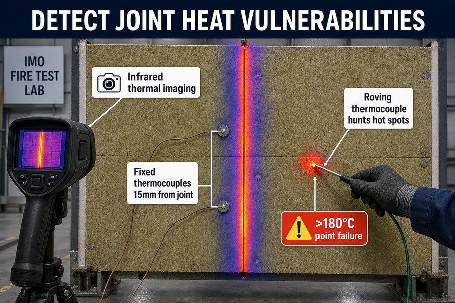
Early heat-transfer vulnerabilities at panel joints are detected using three methods during IMO tests: applying infrared thermal imaging cameras, placing fixed surface thermocouples exactly 15mm from the joint edge, and using the roving thermocouple to hunt for unpredicted hot spots.
Using Infrared Cameras and Fixed Thermocouples at Panel Joints
I spend a lot of time in testing labs. The easiest way to spot a failing joint is by using the first method: an infrared thermal imaging camera11. The inspector stands back and points the camera at the unexposed face. If heat is leaking through a panel joint, the camera shows a bright red or white line on the screen.
Once the camera spots the heat, the inspector relies on the second method. The IMO FTP Code Part 3 requires labs to attach fixed surface thermocouples near the joints before the test starts. The rules state these must be placed exactly 15mm away from the joint line. These fixed sensors record the temperature data every minute. If a joint leaks heat, these sensors will catch the temperature rising too fast.
Deploying the Roving Thermocouple to Find Unpredicted Hot Spots
The third and most dangerous method for suppliers is the roving thermocouple. The fixed sensors only measure specific spots. But fire is unpredictable. If the inspector sees a strange hot patch with the infrared camera, they will pick up a handheld roving thermocouple.
The inspector walks up to the hot panel and presses the roving thermocouple directly onto the suspected weak spot. If that specific spot is over 180°C above the ambient temperature, the panel fails the test immediately. I once watched an inspector fail a $5,000 panel test because the roving thermocouple found a tiny gap that leaked heat at the top corner of a joint.
| Detection Method | Location Used | IMO Testing Purpose |
|---|---|---|
| Infrared Camera | Stand-off distance. | Visually maps out overall heat leaks. |
| Fixed Thermocouples | Exactly 15mm from joint edge. | Records continuous data for the lab report. |
| Roving Thermocouple | Any suspected hot spot. | Hunts for unpredicted point failures > 180°C. |
By using infrared cameras, fixed sensors, and the roving thermocouple, inspectors ensure the joints are perfectly safe. You should ask your suppliers for videos of their panels surviving these three detection methods.
Conclusion
Understanding core density, failure triggers, and IMO test rules helps you buy the right marine interior panels. This knowledge prevents costly rework and builds trust with major shipyard clients.
-
"What Is the Purpose and Scope of the IMO FTP Code?", https://magellanmarinetech.com/what-purpose-scope-of-imo-ftp-code/. The IMO FTP Code Part 3 establishes the laboratory fire-test method and A-class division criteria used for A-60 ratings, while certified panel approvals or test reports document the tested insulation configuration; this supports the regulatory context but does not by itself prove a universal 120–150 kg/m³ rock-wool density requirement. Evidence role: definition; source type: institution. Supports: The article attributes a 120–150 kg/m³ rock-wool density range to the IMO FTP Code Part 3 for A-60 class panels.. Scope note: Contextual support only unless paired with an approval certificate or test report that specifies the rock-wool density range. ↩
-
"Material Thermal Properties Database - FireBID", http://www.firebid.umd.edu/material-database.php. Heat-transfer and thermodynamics references derive the relation Q = m c ΔT, showing that, for the same material and heat input, a larger mass requires more energy to reach the same temperature rise; this explains the thermal-inertia mechanism but does not alone establish an A-60 fire rating. Evidence role: mechanism; source type: education. Supports: More mass in a panel core can slow temperature rise under heat exposure.. Scope note: Panel geometry, facings, joints, moisture, density distribution, and fire exposure conditions also affect heating rate. ↩
-
"Determination of Thermal Properties of Mineral Wool Required for ...", https://pmc.ncbi.nlm.nih.gov/articles/PMC10488771/. Independent material-property references commonly report mineral or rock wool insulation thermal conductivity values in the approximate 0.03–0.04 W/m·K range near room temperature, supporting the stated order of magnitude for 0.034 W/m·K. Evidence role: statistic; source type: research. Supports: Marine-grade rock wool can have thermal conductivity of about 0.034 W/mK at room temperature.. Scope note: Thermal conductivity varies with product formulation, density, mean temperature, moisture, and test standard, so the value should be treated as typical rather than universal. ↩
-
"Determination of Thermal Properties of Mineral Wool Required for ...", https://pmc.ncbi.nlm.nih.gov/articles/PMC10488771/. Material-property references for stone wool or mineral wool list specific heat capacities near 0.8–0.85 kJ/kg·K, supporting the stated value of about 0.84 kJ/kg·K as a typical property. Evidence role: statistic; source type: paper. Supports: Marine rock wool has a specific heat capacity of about 0.84 kJ/kgK.. Scope note: The exact heat capacity can vary with mineral composition, binder content, temperature, and measurement method. ↩
-
"Exploring the Thermal Degradation of Bakelite - PMC - NIH", https://pmc.ncbi.nlm.nih.gov/articles/PMC12390329/. Thermogravimetric studies of phenolic resin and mineral-wool binder systems report substantial thermal decomposition and mass loss in the approximate 200–300°C range, supporting the claim that organic binder integrity can be lost before the mineral fibers themselves fail; the evidence is material-specific and does not prove the exact threshold for every commercial ceiling panel. Evidence role: mechanism; source type: paper. Supports: Phenolic or organic binders in rock-wool ceiling cores can thermally degrade at around 250°C, weakening the bonded fiber structure.. Scope note: Thermal degradation temperature varies with resin formulation, additives, oxygen availability, heating rate, and panel construction. ↩
-
"What Is the Purpose and Scope of the IMO FTP Code?", https://magellanmarinetech.com/what-purpose-scope-of-imo-ftp-code/. The IMO Fire Test Procedures Code Part 3 specifies temperature-rise criteria for fire-resisting divisions, including a maximum unexposed-face temperature rise for individual points, supporting the stated pass/fail threshold; the criterion applies within the defined FTP Code test context and classification scheme. Evidence role: definition; source type: institution. Supports: Under IMO FTP Code Part 3, a marine ceiling or division can fail the insulation criterion if a single point on the unexposed face exceeds the allowed temperature rise, stated here as 180°C above ambient.. Scope note: The threshold should be verified against the exact FTP Code edition and the relevant division class being discussed. ↩
-
"What Is the Purpose and Scope of the IMO FTP Code?", https://magellanmarinetech.com/what-purpose-scope-of-imo-ftp-code/. The IMO FTP Code criteria for A-class divisions limit the average temperature rise on the unexposed face to no more than 140°C above the initial temperature, with additional limits for individual measurement points. Evidence role: definition; source type: institution. Supports: A-class marine panel testing uses a 140°C average unexposed-face temperature-rise limit.. Scope note: This supports the regulatory pass/fail temperature-rise criterion, not the article’s causal explanation that saturation will necessarily make the cold-side temperature rise rapidly. ↩
-
"Thermal buckling and postbuckling of columns accounting ...", https://web.mst.edu/vbirman/papers/ThermalBuckling_2022.pdf. Engineering fire-design references for structural steel quantify substantial thermal elongation at elevated temperatures, including around 800°C, which supports the mechanism that restrained steel sheets can develop compressive stresses and buckle under fire exposure. Evidence role: mechanism; source type: government. Supports: Galvanized steel face plates exposed to about 800°C undergo significant thermal expansion, and restraint can contribute to buckling or warping.. Scope note: The evidence supports the thermal-expansion mechanism generally; it may not directly test the specific ceiling-panel geometry or galvanized face-plate thickness described in the article. ↩
-
"Industrial Thermal Insulation Properties above Sintering Temperatures", https://pmc.ncbi.nlm.nih.gov/articles/PMC8398813/. High-temperature testing and material data for mineral or stone wool insulation report dimensional changes and shrinkage under severe heat exposure, which can contextualize a 2–3% shrinkage estimate near 900°C for some rock-wool products. Evidence role: statistic; source type: paper. Supports: A rock-wool insulation core can shrink by roughly 2% to 3% when exposed to temperatures near 900°C.. Scope note: Shrinkage varies by manufacturer, density, binder content, loading, and test standard, so a source may support this as a plausible range rather than a universal value for every rock-wool core. ↩
-
"Methods for improving the thermal performance of thermal bridges of ...", https://pmc.ncbi.nlm.nih.gov/articles/PMC11651610/. Thermal-bridging studies of steel-framed assemblies show that steel members, because of their high thermal conductivity, can create preferential heat-flow paths through otherwise insulated constructions. Evidence role: mechanism; source type: paper. Supports: Steel edges in a panel joint can act as fast heat-transfer paths.. Scope note: This supports the general heat-bridge mechanism, but does not directly test the specific marine panel joint profile described in the article. ↩
-
"[PDF] Development of Thermal - Envelope Design Guidelines", https://nvlpubs.nist.gov/nistpubs/Legacy/IR/nistir4416.pdf. A neutral source on infrared thermography can support that thermal cameras detect emitted infrared radiation and display surface-temperature patterns, which can reveal localized hot areas on an unexposed face during testing. Evidence role: mechanism; source type: encyclopedia. Supports: An infrared thermal imaging camera can be used to spot heat leaking through a panel joint by showing localized hot areas.. Scope note: This supports the operating principle of thermal imaging, not the specific visual color palette or pass/fail outcome of any IMO test. ↩