
Choosing marine wall panels feels simple until a minor thickness error halts your shipyard project. Incorrect sizes cause failed inspections and wasted money. Let us fix this before you buy.
Incorrect marine accommodation panel thickness creates four major risks: structural deflection from thin panels, increased deadweight from overdesign, reduced usable cabin interior space, and edge crushing at fixing points. Both oversized and undersized panels cause installation failures, leading to delayed shipyard deliveries and costly replacements.
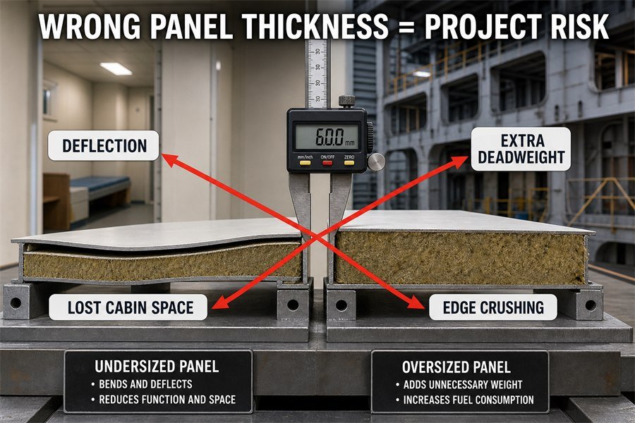
You might think you can stop reading here because a few millimeters of wall thickness seems like a minor detail. I have seen many buyers lose their entire project profit because they ignored these exact rules and trusted the factory blindly. If you do not read the rest of this guide, you will likely make the same expensive mistakes on your next container order.
What Happens When an Accommodation Wall Panel Is Too Thin for Its Fastening Span?
You order cheaper, thinner panels to save budget, but they rattle during installation. Thin panels fail under ship vibrations, costing you more to replace them. Here is the solution.
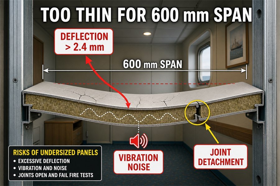
When a marine wall panel is too thin for its fastening span, three things happen: severe structural deflection under load, acoustic failure from excessive vibration, and joint detachment. This means the 25mm or 30mm panel cannot bridge a standard 600mm span, failing SOLAS integrity tests.
Understanding Structural Deflection in Thin Marine Panels
When you design a ship cabin, you must match the wall thickness to the distance between the steel supports. This distance is the fastening span. A standard B-15 marine wall panel is usually 50mm thick. This 50mm thickness gives the wall enough strength to stay straight. If you try to save money and use a 25mm or 30mm panel for a standard 600mm span, you will face severe structural deflection. Deflection means the wall bends in the middle.
According to general marine outfitting standards, wall deflection should not exceed 1/250 of the span length under a standard 25 kg/m2 wind or air pressure load. For a 600mm span, the maximum allowed bending is 2.4mm. A 25mm panel is too weak. It might deflect 5mm or more1. This heavy bending causes the PVC surface film to stretch and crack over time. The shipyard inspector will see the curved walls and reject the entire deck.
Acoustic Failure and Joint Detachment from Vibration
The problems do not stop at bending. Thin panels cause acoustic failure. A ship engine creates constant vibration. A 50mm rockwool panel absorbs this energy well. A 30mm panel vibrates like a drum. I had a client in 2018 who used 30mm panels on a 600mm span. The noise level inside the cabin reached 65 dB. This failed the International Maritime Organization (IMO) limit of 60 dB for standard crew cabins.
Also, this constant shaking leads to joint detachment. Marine panels connect using a tongue-and-groove system. When the thin wall shakes back and forth, the joints pull apart. The fire seal breaks. You then fail the SOLAS fire integrity test. You must replace all the panels.
| Panel Thickness | Fastening Span | Deflection Risk | Acoustic Performance | Joint Stability |
|---|---|---|---|---|
| 50mm (Standard) | 600mm | Low (<2.4mm) | Pass (under 60 dB) | Stable |
| 30mm | 600mm | High (>4.0mm) | Fail (over 60 dB) | High Risk of Detachment |
| 25mm | 600mm | Severe (>5.0mm) | Fail (over 65 dB) | Guaranteed Detachment |
How Does Overdesigning Panel Thickness Negatively Impact Vessel Deadweight?
You choose the thickest panels, thinking thicker means better quality. But heavy walls eat up the ship's cargo capacity. This mistake ruins the vessel's earning potential. Let us analyze this.
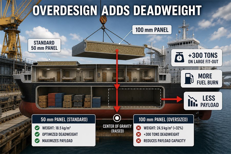
Overdesigning panel thickness negatively impacts vessel deadweight in three ways: it increases total fuel consumption, reduces maximum cargo payload capacity, and alters the ship's vertical center of gravity. Moving from a standard 50mm panel to an unnecessary 100mm panel adds tons of dead steel weight.
Increased Total Fuel Consumption from Heavy Wall Panels
Ship owners hate extra weight. Every kilogram matters. When you buy interior materials, you must think about the whole ship. A standard 50mm rockwool core B-15 panel weighs about 18.5 kg/m2. This calculation uses a standard 120 kg/m3 rockwool density and a 0.6mm galvanized steel skin. If you overdesign and specify a 100mm panel just to feel safer, the weight jumps to about 24.5 kg/m2.
If you are fitting out a large cruise ship or a ferry with 50,000 square meters of wall panels, that extra 6 kg/m2 adds up fast. You just added 300 metric tons of deadweight to the ship. According to naval architecture rules, pushing an extra 300 tons through the water requires more engine power.2 This increases total fuel consumption. The ship might burn 1.5 to 2 extra tons of marine diesel oil every day.3 At current fuel prices, that wastes over a thousand dollars daily.
Reduction in Cargo Payload Capacity and Changed Center of Gravity
Because the ship now carries 300 tons of extra wall panels, it must carry less cargo. The ship owner loses money on every trip. This causes a direct reduction in cargo payload capacity.4 The shipyard will blame you for this commercial loss.
Also, you must think about where these walls go. Most accommodation blocks are on the upper decks. Adding hundreds of tons high up on the ship alters the vertical center of gravity (VCG). A higher VCG makes the ship top-heavy.5 The ship will roll more in rough seas. In the worst cases, the ship might fail its mandatory stability incline test. The shipyard would have to add solid iron ballast to the bottom of the ship, wasting even more fuel and cargo space.
| Panel Specification | Weight per m2 | Total Weight (50,000 m2) | Impact on Fuel Consumption | Impact on Payload |
|---|---|---|---|---|
| 50mm Panel (Standard) | 18.5 kg | 925 Metric Tons | Baseline | Baseline |
| 75mm Panel | 21.5 kg | 1,075 Metric Tons | Moderate Increase | Loses 150 Tons |
| 100mm Panel | 24.5 kg | 1,225 Metric Tons | High Increase | Loses 300 Tons |
How Does Excessive Panel Thickness Reduce Usable Cabin Interior Volume?
Thick marine walls squeeze the space inside ship cabins. Your shipyard client measures the room, finds it too small, and stops your payment. Here is how to protect your space.
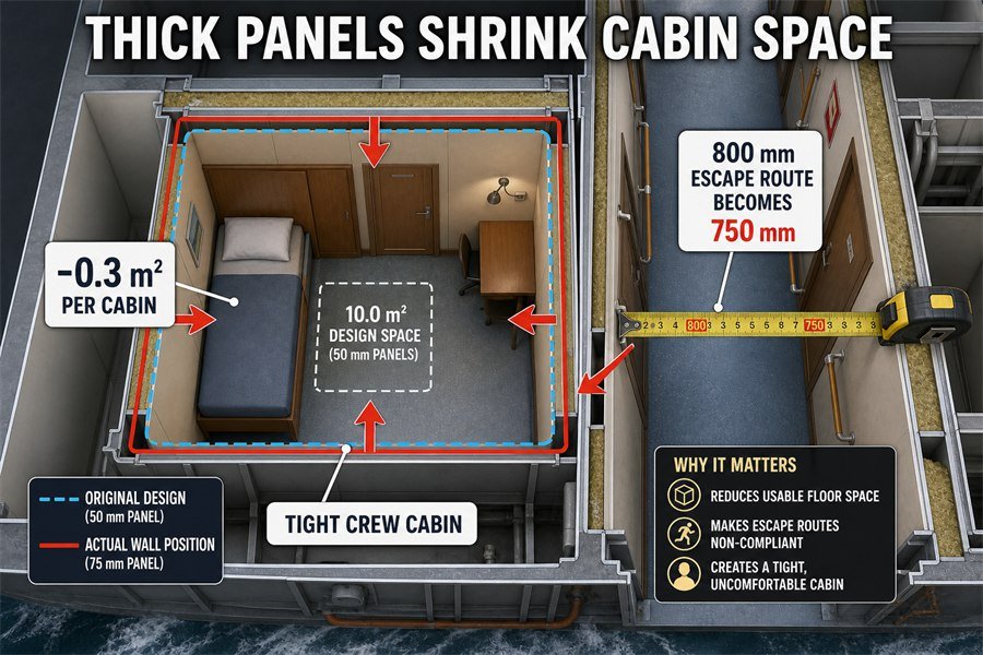
Excessive panel thickness reduces usable cabin interior volume by causing three major issues: lost floor space, non-compliant narrow passage widths, and a tight cabin feel for crew. Adding 25mm to every wall shrinks a standard 10-square-meter cabin significantly, failing maritime labor convention space rules.
Lost Floor Space in Standard Marine Cabins
Space on a ship is very expensive. Ship designers calculate every millimeter. The Maritime Labour Convention (MLC 2006) has strict rules about space. It states that a single-occupancy seafarer cabin on a ship over 3,000 gross tons must have a minimum floor area of 5.5 square meters. Many modern ship designs target a 10-square-meter gross space to add furniture and a bathroom.
If you use a 75mm thick panel instead of the specified 50mm panel, you add 25mm to each wall. Imagine a cabin that is 3 meters by 3.3 meters. If all four inner walls push inward by 25mm, you lose a lot of space. You lose about 0.3 square meters of usable floor area per cabin. This creates a tight cabin feel for the crew. On a medium vessel with 500 cabins, you lose 150 square meters of total interior space. That is the size of 15 entire cabins completely wiped out by thick walls.
Non-Compliant Narrow Passage Widths and Crew Comfort
Excessive thickness also destroys the ship's safety layout. Standard public corridors on a ship must maintain specific clear widths for emergency escape routes6. Usually, the fire plan requires an 800mm clear passage width. If you install panels that are too thick, they push into the corridor.
The corridor might shrink from 800mm to 750mm. This results in non-compliant narrow passage widths. When the classification society inspector walks the ship with a tape measure, they will check these escape routes. If the route is only 750mm wide, they will refuse to issue the safety certificate. You will have to tear down all the corridor walls and buy new, thinner panels. This ruins your project timeline and destroys your profit margin.
| Area of Impact | 50mm Panel Design | 75mm Panel Reality | Result of Excessive Thickness |
|---|---|---|---|
| Cabin Floor Area | 10.0 sq meters | 9.7 sq meters | Fails crew comfort standards |
| Corridor Escape Route | 800mm clear width | 750mm clear width | Fails safety inspection |
| Total Space (500 Cabins) | 5,000 sq meters | 4,850 sq meters | Loses 150 sq meters of volume |
What Thickness Errors Cause Panel Edge Crushing at Fixing Points?
You push a thick panel into a narrow floor track, and the metal edge bends. Ruined panels look terrible and fail fire tests. Fixing this wastes time and materials. Let us prevent this damage.
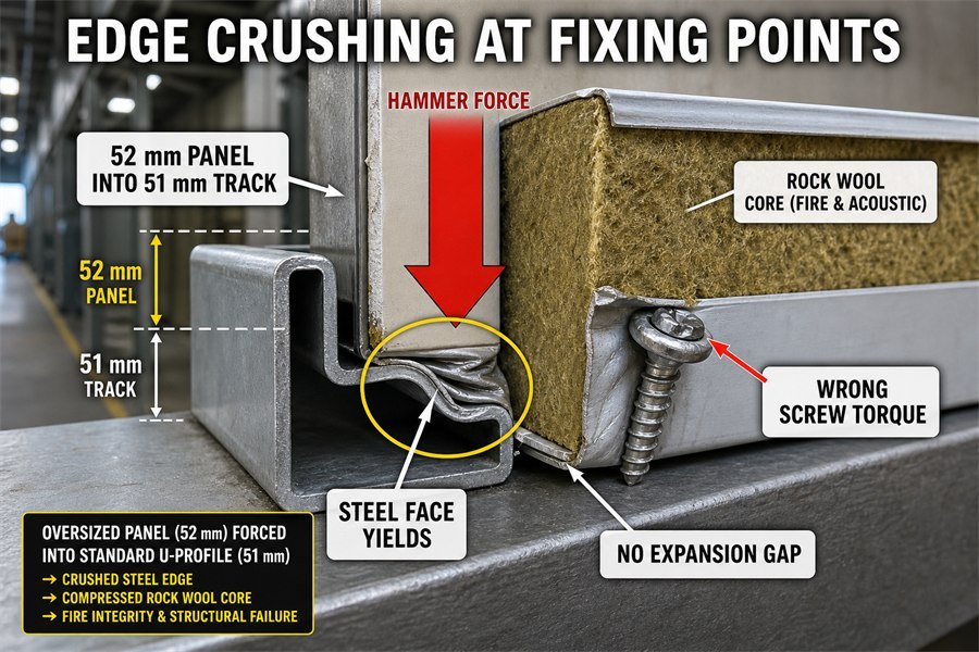
Panel edge crushing at fixing points is caused by three thickness errors: forcing oversized panels into standard U-profiles, using wrong screw torque on thin skins, and restricting thermal expansion space. When a 52mm panel is jammed into a 50mm base track, the steel face yields and crushes.
Forcing Oversized Marine Panels into Standard U-Profiles
Marine wall panels sit inside metal tracks. We call the bottom track a base U-profile. The factory bends this U-profile precisely to hold a specific panel. The inner gap of a standard U-profile is usually 51mm.7 This allows a 1mm tolerance for a 50mm panel to slide in easily.
If your supplier has poor quality control, they might send you a panel with a 52mm thickness. When the shipyard workers try to install it, the panel does not fit. Workers do not want to stop their job, so they will force oversized panels into the track with heavy rubber hammers. This force crushes the 0.6mm galvanized steel face at the bottom edge. Inside the panel, the rockwool core gets compressed from a 120 kg/m3 density to a 140 kg/m3 density at the base. This breaks the fire integrity of the wall.8
Incorrect Screw Torque and Restricting Thermal Expansion Space
Edge crushing also happens from the tools we use. If the factory uses a steel skin that is too thin, like 0.4mm instead of the standard 0.6mm, the edge becomes very weak. When workers use electric drill guns to fix self-tapping screws, they apply torque. Standard 0.6mm steel handles 3 to 4 Nm of torque well.9 If you use the wrong screw torque of 5 Nm on a thin 0.4mm skin, the screw head crushes right through the metal edge.
Also, a panel that is too thick fits too tightly inside the side profiles. It leaves zero gap for movement. Steel expands when it gets hot. A standard steel panel expands about 1.2mm per meter during a 100°C temperature change10. By restricting thermal expansion space, the panel has nowhere to grow during a fire or in a hot engine room. The edge pushes against the hard steel track and crushes itself under its own pressure.
| Thickness Error Type | Mechanical Cause | Physical Result on Panel Edge | Solution |
|---|---|---|---|
| Oversized Panel (52mm) | Hammered into 51mm track | Steel skin yields and bends | Reject panels outside +0.5mm tolerance |
| Undersized Skin (0.4mm) | 5 Nm screw torque applied | Screw crushes through metal | Verify 0.6mm skin thickness before buying |
| Zero Expansion Gap | Metal expands 1.2mm/m | Edge buckles against hard track | Maintain 1mm clearance in all profiles |
How Is Thickness Verified Against a Marine Accommodation Panel Data Sheet?
Trusting the label without checking the real panel leads to massive installation failures. You find out too late that the panels are wrong. You must measure them yourself using the right tools.
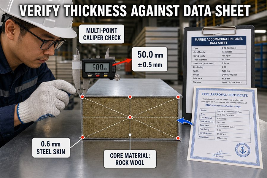
Thickness is verified against a marine accommodation panel data sheet through three key steps: conducting multi-point caliper checks on the steel skin, confirming the rockwool core density thickness, and matching these results with the Type Approval Certificate. Measurements must stay within the standard ±0.5mm factory tolerance.
Conducting Multi-Point Caliper Checks on Steel Skins
When a container of wall panels arrives at your warehouse from China or Vietnam, do not just read the paper packing list. You need to inspect the physical goods immediately. You must use a digital vernier caliper. According to ISO 2768-m, general tolerances for these industrial panels should be strictly controlled. A reliable factory maintains a ±0.5mm tolerance on the total thickness of a 50mm panel.
First, conduct multi-point caliper checks. Measure the total thickness at all four corners and the center of the panel. The caliper should read between 49.5mm and 50.5mm. Second, check the steel skin itself. The manufacturer data sheet might say 0.6mm galvanized steel. Use a micrometer on the raw metal edge. If your tool shows 0.45mm or 0.5mm, the factory cheated to save material costs. This thin skin will cause the structural failures we discussed earlier.
Confirming Core Density Thickness and Matching Type Approval Certificates
The inside of the panel is just as important as the outside. You must confirm the rockwool core density thickness. If you can inspect a cut panel or an unsealed edge, measure the rockwool block. The core must match the exact fire test report.
Marine materials depend heavily on paper documentation. You must match your physical measurements with the Type Approval Certificate from classification societies like DNV, ABS, or Lloyd's Register. If the DNV certificate says the A-60 rated panel must have a 50mm core at a 150 kg/m3 density, your physical check must prove this. If the factory put a 45mm core inside to save money, the fire rating is completely void. The shipyard will reject the panels, and they will not pay your company.
| Verification Step | Tool Required | Standard Target Value | Acceptable Tolerance |
|---|---|---|---|
| Total Panel Thickness | Digital Vernier Caliper | 50.0 mm | ± 0.5 mm |
| Steel Skin Thickness | Metal Micrometer | 0.6 mm | ± 0.05 mm |
| Rockwool Core Thickness | Measuring Tape / Caliper | 50.0 mm (varies by rating) | ± 1.0 mm |
| Documentation Match | DNV / ABS Certificate | Matches physical check | Zero deviation allowed |
Conclusion
Incorrect marine panel thickness ruins structural integrity, wastes ship fuel, shrinks cabin spaces, and causes severe installation damage. Always verify exact measurements against data sheets to secure your shipyard profits and safety.
-
"[PDF] Virtually every aircraft has some sandwich structure Replaces skin ...", https://www.usna.edu/Users/mecheng/pjoyce/composites/Short_Course_2003/13_PAX_Short_Course_Sandwich-Constructions.pdf. A structural mechanics source on sandwich or composite panel bending can support the general relationship between reduced panel thickness and increased mid-span deflection under transverse load; unless the source tests the same 25 mm panel construction, it provides contextual support rather than direct proof of a 5 mm deflection value. Evidence role: mechanism; source type: paper. Supports: A 25 mm panel over a 600 mm span can deflect substantially more than a thicker panel and may exceed acceptable deflection limits.. Scope note: Direct support for the exact 5 mm figure would require test data or a calculation for the same panel materials, core, skins, span, and load. ↩
-
"[PDF] Chapter 7 Resistance and Powering of Ships - USNA", https://www.usna.edu/NAOE/_files/documents/Courses/EN400/02.07%20Chapter%207.pdf. Standard naval-architecture references describe ship resistance and required propulsive power as functions of displacement, draft, hull form, and speed; added displacement generally increases the power needed to maintain a given service speed. Evidence role: mechanism; source type: education. Supports: Pushing an extra 300 tons through the water requires more engine power.. Scope note: This supports the physical relationship qualitatively, but it does not by itself quantify the effect of an added 300 metric tons for a specific hull. ↩
-
"Data Fusion and Machine Learning for Ship Fuel Consumption ...", https://arxiv.org/html/2509.11750v1. Studies of ship fuel consumption commonly model fuel use as dependent on required propulsion power, displacement or loading condition, and operating speed, providing context for estimating additional daily fuel burn from added weight. Evidence role: statistic; source type: paper. Supports: An added 300 tons of panel weight could increase daily marine diesel consumption by about 1.5 to 2 tons.. Scope note: Such sources can justify the method and order-of-magnitude reasoning, but the exact 1.5–2 tons per day figure would require vessel-specific speed, hull, engine, and route assumptions. ↩
-
"Deadweight tonnage - Wikipedia", https://en.wikipedia.org/wiki/Deadweight_tonnage. Maritime definitions of deadweight capacity treat cargo, fuel, stores, ballast, passengers, and other carried weights as components of the same allowable load; therefore, increased lightship or outfitting weight reduces available payload when the vessel’s deadweight limit is fixed. Evidence role: definition; source type: institution. Supports: Extra permanent panel weight reduces the cargo payload capacity available to the owner.. Scope note: The exact commercial payload loss depends on the vessel’s loading condition, statutory limits, and whether design margins are available. ↩
-
"[PDF] Chapter 2 - Review of Intact Statical Stability - USNA", https://www.usna.edu/NAOE/_files/documents/Courses/EN455/EN455_Chapter2.pdf. Ship-stability guidance explains that raising the vertical centre of gravity reduces metacentric height and transverse stability, which is the technical basis for describing a vessel as more top-heavy. Evidence role: mechanism; source type: government. Supports: Adding weight high in the ship raises VCG and makes the vessel more top-heavy by reducing stability margins.. Scope note: This supports the stability mechanism generally, but whether a particular vessel becomes unsafe depends on its full stability booklet and loading condition. ↩
-
"46 CFR 177.500 -- Means of escape. - eCFR", https://www.ecfr.gov/current/title-46/chapter-I/subchapter-T/part-177/subpart-E/section-177.500. IMO fire-safety regulations and related interpretations require ships to provide regulated means of escape from accommodation and service spaces, including dimensional requirements for escape routes; this supports the need to preserve clear corridor widths, although the applicable numerical width depends on ship type and regulatory regime. Evidence role: definition; source type: institution. Supports: Standard public corridors on a ship must maintain specific clear widths for emergency escape routes.. Scope note: The source may establish regulated escape-route dimensions generally rather than the exact 800 mm figure used in the article. ↩
-
"[PDF] National Security Multi-Mission Vessel - Maritime Administration", https://www.maritime.dot.gov/sites/marad.dot.gov/files/docs/national-defense/office-ship-operations/rrf/2576/nsmv-outline-specification.pdf. A classification-society rule, shipyard standard, or manufacturer-independent marine accommodation specification should document the nominal profile gap used with 50 mm wall panels; if the source only lists a representative system, it supports this as an industry example rather than a universal standard. Evidence role: general_support; source type: institution. Supports: A standard marine base U-profile commonly has an inner gap of about 51 mm for a 50 mm wall panel.. Scope note: Marine panel profile dimensions can vary by system, supplier, class notation, and project specification. ↩
-
"[PDF] comdtpub p16700.4 - ROSA P", https://rosap.ntl.bts.gov/view/dot/63887/dot_63887_DS1.pdf. IMO FTP Code materials or classification-society fire-test guidance can support that fire-rated marine bulkhead assemblies are certified as tested systems and that changes to joints, edges, facings, or insulation can compromise the demonstrated fire integrity; such evidence would support the principle but may not directly prove failure from the stated 120-to-140 kg/m³ compression scenario. Evidence role: expert_consensus; source type: institution. Supports: Crushing or compressing the edge of a fire-rated marine wall panel can compromise the wall’s certified fire integrity.. Scope note: The cited source may establish that alterations can invalidate or compromise a tested fire-rated assembly, not that this exact compression amount always breaks fire integrity. ↩
-
"[PDF] Installation Torque Tables for Noncritical Applications", https://ntrs.nasa.gov/api/citations/20170003491/downloads/20170003491.pdf. A mechanical-engineering study, fastener standard, or technical handbook on self-tapping screws in thin steel sheet can support typical tightening torque ranges and failure modes for sheet-metal fasteners; the evidence should be treated as contextual unless it tests the same 0.6 mm galvanized steel skin and screw geometry. Evidence role: mechanism; source type: paper. Supports: A 0.6 mm steel skin can tolerate roughly 3–4 Nm of self-tapping screw torque without edge crushing under typical conditions.. Scope note: Torque capacity depends on screw diameter, thread form, washer/head geometry, steel grade, coating, hole preparation, and installation speed. ↩
-
"[PDF] Thermal Expansion - Rice University", https://www.owlnet.rice.edu/~msci301/ThermalExpansion.pdf. Reference data for carbon steel’s linear thermal expansion coefficient, approximately 12 × 10⁻⁶/K near room temperature, supports the calculation that a 1 m steel member lengthens by about 1.2 mm for a 100°C temperature rise. Evidence role: mechanism; source type: education. Supports: A standard steel panel expands about 1.2 mm per meter for a 100°C temperature change.. Scope note: The coefficient varies with alloy, temperature range, and constraint conditions, so the value is an engineering approximation. ↩