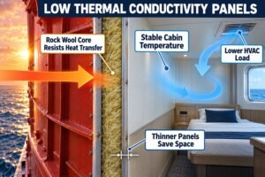
Ship retrofits are stressful. Low ceilings can ruin your design and cause inspection failures. Let us look at how height limits affect your marine ceiling panel choices.
Ceiling height limits restrict retrofit marine ceiling panel choices by dictating the maximum panel thickness, suspension system depth, and void clearance needed for pipes and cables, ensuring the final installation complies with ILO/MLC minimum headroom requirements of 1980mm.
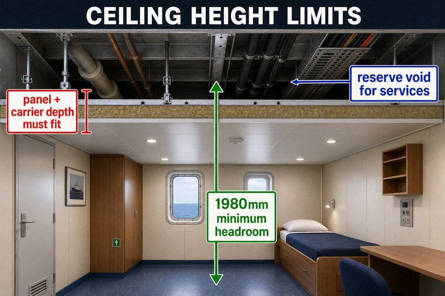
You might think any thin panel works, but legal compliance and hidden systems make it tricky. Let us break down the exact rules and clearances you need to know.
What Minimum Ceiling Height Ensures ILO/MLC Compliance With New Retrofit Ceiling Panels?
Failing an inspection costs time and money. If your new panels sit too low, the cabin fails MLC rules. Let us look at the minimum height you need.
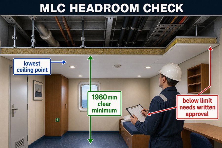
To ensure ILO/MLC compliance with new retrofit ceiling panels, the absolute minimum clear ceiling height must be 1980mm (77.9 inches) from the finished deck to the lowest point of the ceiling panel in all seafarer accommodations, though competent authorities may permit limited reductions in certain areas.
Understanding the ILO/MLC 1980mm Headroom Requirement
When I worked at the marine outfitting factory, I saw many buyers struggle with regulations. The most important rule for ceiling height comes from the Maritime Labour Convention (MLC) 2006. Under Title 3 of this convention, the standard clear headroom in seafarer sleeping rooms and living spaces must be at least 1980mm1. This is exactly 77.9 inches. You must measure this distance from the top of the finished floor covering to the lowest point of the ceiling panel above2.
You cannot ignore this number. If you buy a ceiling panel that hangs too low and makes the room 1950mm high, the ship will fail its class survey. You will have to tear down the entire ceiling and buy new materials. This causes huge project delays. Therefore, before you buy any marine ceiling panel, you must measure the bare steel room first. You must subtract the height of your new flooring. Then, you can see how much space is left to reach the 1980mm mark.
Exceptions and Reductions Permitted by Flag States
The 1980mm rule is very strict. However, the MLC 2006 does allow some small exceptions. A competent authority, like the ship's Flag State, can approve a lower ceiling in specific parts of a room. This is usually allowed if the lower ceiling does not cause discomfort to the crew. For example, a ceiling might drop to 1900mm in a small corner or over a desk.
I always tell my clients to get this approval in writing first. Never assume the inspector will allow a low ceiling. Corridor ceilings can sometimes be slightly lower, but sleeping areas must meet the 1980mm standard. When you plan your interior decoration project, always map out these exception areas.
| Space on Ship | Standard Minimum Height (MLC 2006) | Allowed Exceptions (with Approval) |
|---|---|---|
| Main Sleeping Rooms | 1980mm | None in main walking areas |
| Corners of Cabins | 1980mm | Down to 1900mm (depends on Flag) |
| Bathrooms / Sanitary | 1980mm | Down to 1900mm (depends on Flag) |
| Walkways / Corridors | 1980mm | Down to 1900mm (depends on Flag) |
What Is the Maximum Retrofit Ceiling Panel Thickness to Maintain Class-Approved Cabin Headroom?
Thick fire panels eat up precious space. You need a panel that stops fire but leaves enough headroom. Here is how thick your panels can be.
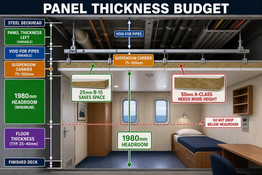
The maximum retrofit ceiling panel thickness to maintain class-approved cabin headroom typically ranges from 25mm to 50mm, with 25mm standard for B-0 or B-15 ratings and up to 50mm for A-class areas, depending on the available deck-to-deck height minus the 1980mm minimum requirement and void space.
Calculating Available Thickness Based on Deck-to-Deck Height
Finding the right panel thickness is a basic math problem. I help my clients calculate this every week. First, measure the total bare steel deck-to-deck height. Let us say it is 2200mm. Next, subtract the legal 1980mm headroom3. You have 220mm left. Then, subtract the floor thickness, which is usually around 40mm. Now you have 180mm.
Finally, you must subtract the void space for pipes and cables above the ceiling. If this void space needs 130mm, you only have 50mm left. This means your maximum ceiling panel thickness is 50mm. If you buy a panel thicker than 50mm, you will break the 1980mm rule. This calculation is the most critical step before you place an order with a factory in China or Vietnam.
Fire Ratings (B-15 vs A-60) Impact on Marine Panel Thickness
The fire rating you need will change the thickness of the panel. For standard cabin ceilings, you usually need a B-0 or B-15 fire rating. These panels are typically 25mm thick. A 25mm marine ceiling panel is great for retrofits because it saves a lot of space. It gives you more room for air ducts above.
However, some areas of the ship need an A-class fire rating. For example, engine room boundaries need A-30 or A-60 ratings4. To stop a fire for 60 minutes, the rock wool core inside the panel must be thicker. These panels are usually 50mm thick. You must balance this 50mm thickness against your total room height. If you use a 50mm panel, you lose an extra 25mm of room height compared to a B-15 panel.
| Fire Class Rating | Common Panel Thickness | Core Material | Best Use Case in Retrofits |
|---|---|---|---|
| C-Class | 15mm - 20mm | Honeycomb / Light Wool | Spaces with no fire risk |
| B-0 / B-15 | 25mm | High-density Rockwool | Standard crew cabins |
| A-30 / A-60 | 50mm | High-density Rockwool | High fire risk boundaries |
How to Fit New Marine Ceiling Panels Under Existing Pipe Runs in Retrofits?
Old ships have messy pipes. Rerouting them is too expensive. You must find ways to install your ceiling right under them.
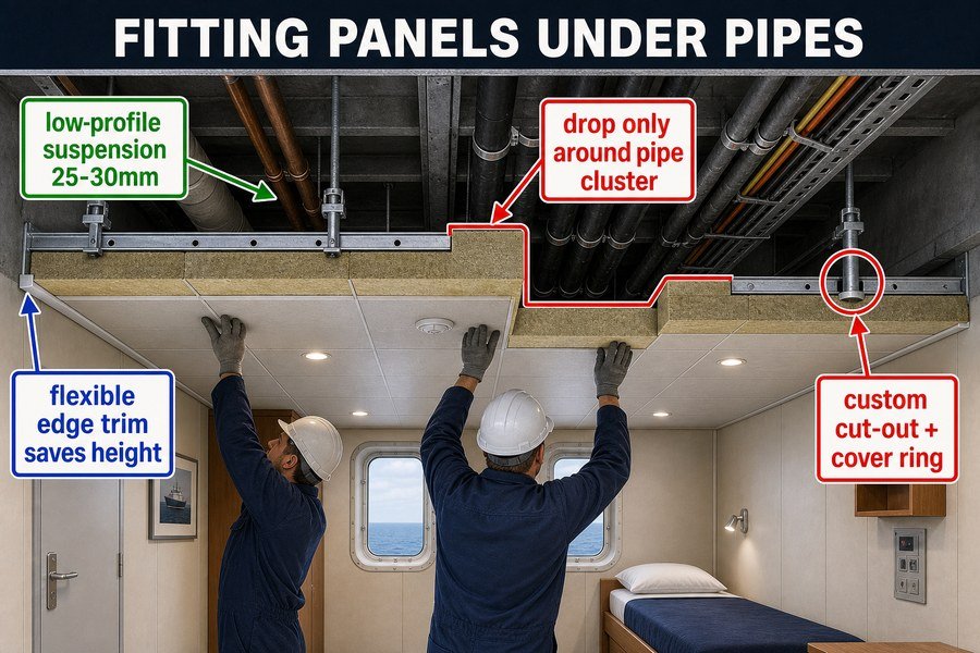
To fit new marine ceiling panels under existing pipe runs in retrofits, you must use low-profile suspension systems, apply custom cut-outs for vertical pipes, install dropped ceiling sections (bulkheads) around major pipe clusters, and use flexible edge trims to secure panels directly beneath lowest pipe flanges.
Using Low-Profile Suspension Systems and Flexible Edge Trims
Old pipes in ships hang low. You cannot move them easily. The best way to save space is by using a low-profile suspension system. Standard ceiling carriers in new ships need about 50mm of space above the panel5. In a retrofit, you do not have 50mm. I advise my clients to buy low-profile C-channel carriers. These only need 25mm to 30mm of space6. This keeps the panel tight against the bottom of the pipes.
Also, you must secure the edges of the ceiling panels. When pipes run very close to the wall, standard wall angles do not fit. You must use flexible edge trims. These trims can be modified to sit right under the lowest pipe flanges. This secures the ceiling panel without lowering the entire room height.
Creating Dropped Ceilings and Cut-Outs Around Major Pipes
Sometimes, a huge pipe cluster hangs too low to hide behind a flat ceiling. If you lower the whole ceiling to hide it, the room fails the 1980mm rule. The solution is to create a dropped ceiling section, also known as a ceiling bulkhead. You keep the main room ceiling at 1980mm or higher. Then, you step the ceiling down just in the small area where the big pipes are. This hides the pipes but keeps the main room tall.
For vertical pipes going through the ceiling, you need custom cut-outs. You must measure the exact diameter of the pipe. Then, cut a matching hole in the ceiling panel at the factory or on the ship. We often add a steel cover ring around the cut-out to make it look clean and keep the fire rating safe.
| Installation Method | Space Saved | Required Tools | Best Used For |
|---|---|---|---|
| Low-Profile Suspension | 20mm - 25mm | Standard carrier clips | Flat ceilings near pipes |
| Flexible Edge Trims | 10mm - 15mm | Snips, rivets | Wall edges under low pipes |
| Dropped Ceiling Sections | 100mm - 200mm | Custom L-profiles | Large pipe clusters |
| Custom Panel Cut-Outs | N/A | Hole saw, steel rings | Vertical pipe crossings |
What Void Clearance Is Required for Retrofit Ceiling Panels and Existing Cable Trays?
Cables get hot and need air. Squashing your ceiling against cable trays is a massive fire risk. Let us check the proper clearances.
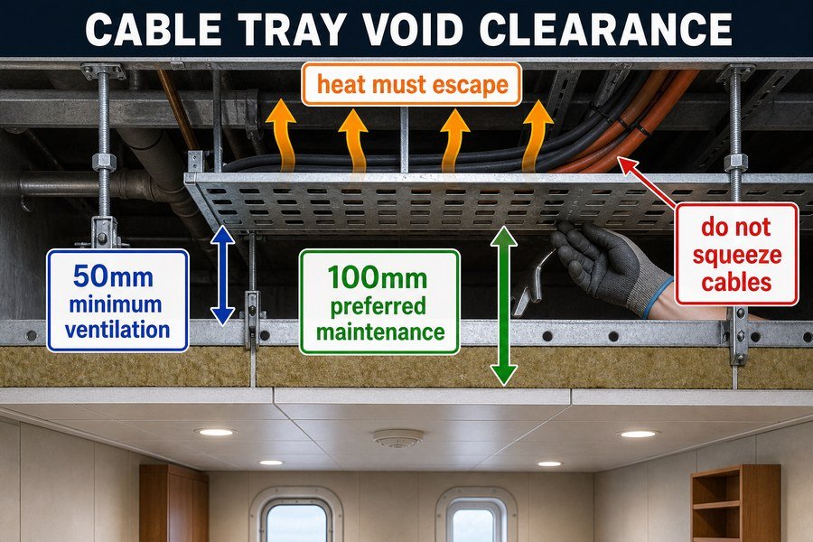
The minimum void clearance required between retrofit ceiling panels and existing cable trays is 50mm to 100mm, providing 50mm for basic ventilation and heat dissipation per IEC standards, while 100mm is often necessary to allow access for maintenance and the physical installation of the ceiling suspension carriers.
The IEC 60092 Rules for 50mm Heat Dissipation Clearance
Ship electrical cables carry heavy loads like 220V or 440V. They generate a lot of heat. If you block this heat, the cables can melt and start a fire. The International Electrotechnical Commission (IEC) sets rules for ships under the IEC 60092 standard. This standard states that cables need open air around them to cool down.
In my experience, you must leave a minimum void clearance of 50mm7 between the top of your new ceiling panel and the bottom of the cable tray. This 50mm gap allows hot air to escape. If you push the ceiling panel directly against the cables to save room height, the ship inspector will fail your project. Always tell your installation team to check the 50mm gap across the whole room.
Why 100mm Void Clearance is Needed for Maintenance and Carrier Installation
While 50mm is the legal minimum for heat, it is rarely enough for actual work. I always suggest a 100mm void clearance if the room height allows it. Why? Because workers need space for physical installation. To hang a marine ceiling panel, workers must push their hands above the panel to lock the suspension carriers and Z-profiles. Human hands and tools need at least 100mm of space to move.8
Also, ships need maintenance. Crew members might need to pull new wires or check old cables in the future. If the gap is only 50mm, they cannot reach the cables. They would have to break the ceiling panels. By planning a 100mm void clearance, you make the installation faster and the future maintenance much easier.
| Clearance Type | Minimum Distance | Primary Reason | Standard / Reference |
|---|---|---|---|
| Ventilation Gap | 50mm | Heat dissipation for cables | IEC 60092 standard |
| Installation Gap | 100mm | Hand access for suspension | Practical shipyard limit |
| Maintenance Gap | 100mm+ | Room to pull new wires | Ship owner preference |
Why Do Thick Suspended Marine Ceiling Panels Conflict With Original Deck Head Heights?
Older vessels were built with lower decks. Trying to force modern, thick ceiling panels into these old spaces causes huge problems.
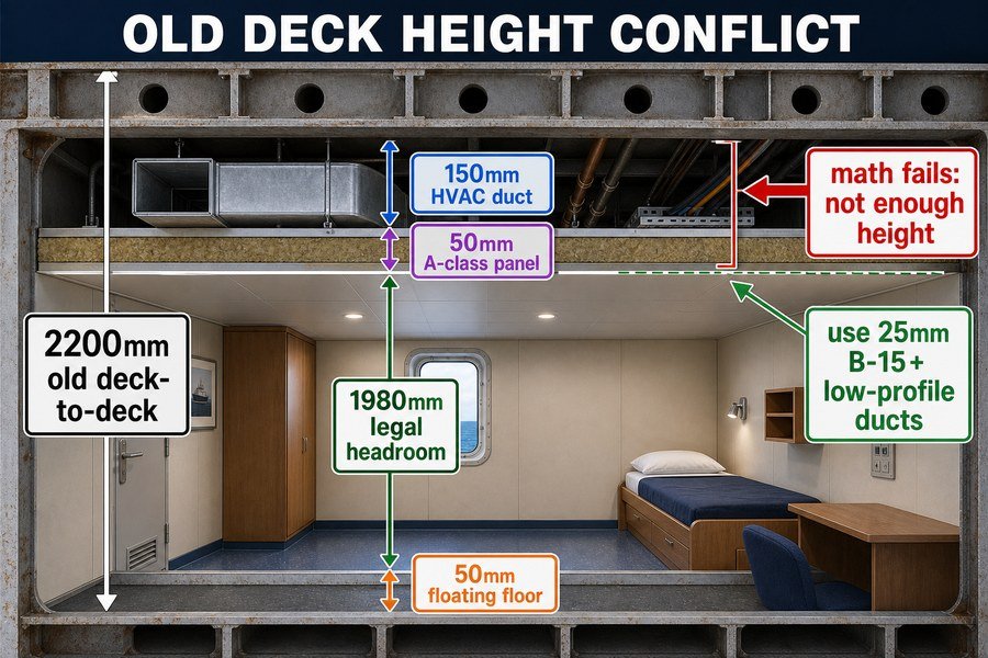
Thick suspended marine ceiling panels conflict with original deck head heights because older ships were designed with deck-to-deck heights around 2200mm, leaving insufficient space to accommodate modern 50mm thick A-class panels, 150mm HVAC ducts, floating floors, and still achieve the modern 1980mm legal headroom requirement.
Historical 2200mm Deck Designs vs 1980mm Clear Headroom Rules
When we supply panels for old ships built in the 1980s or 1990s, we face a major problem. Historical ship design used much lower deck-to-deck heights. A common steel deck height back then was only 2100mm or 2200mm. At that time, regulations were not as strict.
Today, modern regulations like the MLC 2006 demand a clear 1980mm headroom. This clash between old steel design and new legal rules makes your job very hard. If you only have 2200mm of total steel space, and you must keep 1980mm for the crew, you only have 220mm of working space left. You must fit the floor, the ceiling, and everything in between inside this tiny 220mm gap.
How 50mm Panels, Floating Floors, and 150mm HVAC Ducts Consume Space
Let us look at how fast that 220mm gap disappears. First, you add a modern floating floor for noise reduction. This floor takes up 50mm. Now you only have 170mm left. Next, you must install modern HVAC air ducts above the ceiling. These ducts are usually 150mm thick. Now you only have 20mm left.
If you try to install a thick 50mm A-class marine ceiling panel, you are 30mm short. The math does not work. This is the core conflict. To fix this, you must buy thinner panels, like 25mm B-15 panels, and use low-profile square HVAC ducts instead of round ones. Every single millimeter matters when you buy materials for old ship retrofits.
| Ship Component | Typical Thickness / Height Needed | Impact on 2200mm Steel Deck Gap |
|---|---|---|
| Modern Floating Floor | 50mm | Leaves 170mm remaining |
| HVAC Ducts and Pipes | 150mm | Leaves 20mm remaining |
| A-Class Ceiling Panel | 50mm | Fails by 30mm |
| B-15 Ceiling Panel | 25mm | Fails by 5mm (Needs flat ducts) |
Conclusion
Ceiling height limits demand precise calculation of the ILO 1980mm rule, panel thickness, and void clearances. Proper low-profile marine ceiling panels ensure your retrofit project passes class inspections smoothly.
-
"Accommodation of Crews (Supplementary Provisions) Convention ...", https://en.wikipedia.org/wiki/Accommodation_of_Crews_(Supplementary_Provisions)_Convention,_1970. The ILO convention text should be cited to verify the applicable minimum headroom requirement for seafarer accommodation under international maritime labour standards. Evidence role: definition; source type: institution. Supports: The standard clear headroom in seafarer sleeping rooms and living spaces must be at least 1980mm.. Scope note: MLC 2006 Standard A3.1 is often cited as requiring 203 cm where full and free movement is necessary; a 1980 mm figure may relate to earlier ILO accommodation standards, transitional rules, or flag-state interpretations. ↩
-
"[PDF] Proposed new Regulations on safety in passenger spaces", https://www.eftasurv.int/cms/sites/default/files/documents/gopro/%28eng%29%20Forslag%20til%20forskrift%20om%20tryggleik%20i%20passasjeromr%C3%A5de.pdf. A maritime accommodation inspection or design standard can support the method of treating clear headroom as the unobstructed vertical distance from the finished floor level to the lowest overhead obstruction. Evidence role: definition; source type: institution. Supports: The headroom distance should be measured from the top of the finished floor covering to the lowest point of the ceiling panel above.. Scope note: Such sources may define general measurement practice rather than restating this exact wording for every type of ceiling panel installation. ↩
-
"[PDF] Proposed new Regulations on safety in passenger spaces", https://www.eftasurv.int/cms/sites/default/files/documents/gopro/%28eng%29%20Forslag%20til%20forskrift%20om%20tryggleik%20i%20passasjeromr%C3%A5de.pdf. Maritime accommodation standards specify minimum clear-headroom requirements for seafarer spaces, supporting the need to reserve a legally required clear height before calculating allowable ceiling build-up; the precise minimum may vary by flag state, vessel category, and permitted exemptions. Evidence role: general_support; source type: government. Supports: A required legal headroom allowance must be subtracted when calculating maximum marine ceiling panel thickness.. Scope note: The source may support minimum headroom regulation generally rather than the article’s exact 1980 mm value in every jurisdiction. ↩
-
"46 CFR Part 116 Subpart D -- Fire Protection - eCFR", https://www.ecfr.gov/current/title-46/chapter-I/subchapter-K/part-116/subpart-D. IMO/SOLAS fire-safety rules define A-class divisions and time-rated insulation criteria such as A-30 and A-60, supporting the claim that higher-risk ship boundaries may require time-rated fire-resisting construction; application to a specific engine-room boundary depends on the vessel’s regulatory category and approved fire-control plan. Evidence role: definition; source type: institution. Supports: Some ship areas, such as engine-room boundaries, may require A-class fire ratings such as A-30 or A-60.. Scope note: The source defines the rating system and regulatory context, but it does not by itself prove that every engine-room boundary requires A-30 or A-60 construction. ↩
-
"[PDF] IR 25-2: Suspended Lay-In Panel Ceiling: 2019 CBC - DGS.ca.gov", https://www.dgs.ca.gov/-/media/Divisions/DSA/Publications/interpretations_of_regs/IR_25-2-19.pdf. A class-society accommodation-outfitting guide or approved marine ceiling installation manual documents typical suspended-ceiling carrier build-up depths and supports the use of approximately 50 mm as a conventional clearance allowance. Evidence role: general_support; source type: institution. Supports: Standard ceiling carriers in new ships need about 50mm of space above the panel.. Scope note: Carrier depth varies by ceiling system, manufacturer, fire rating, and installation detail; the source would contextualize the figure rather than establish a universal rule. ↩
-
"[PDF] IR 25-2: Suspended Lay-In Panel Ceiling: 2019 CBC - DGS.ca.gov", https://www.dgs.ca.gov/-/media/Divisions/DSA/Publications/interpretations_of_regs/IR_25-2-19.pdf. Technical installation data for low-profile marine C-channel ceiling carriers supports that some low-profile suspension systems can be installed with roughly 25–30 mm of overhead clearance. Evidence role: general_support; source type: institution. Supports: Low-profile C-channel carriers only need 25mm to 30mm of space.. Scope note: This support is product- and approval-specific; it would show that such low-profile systems exist, not that every low-profile C-channel carrier meets this clearance range. ↩
-
"(PDF) Electrical installations in ships – Part 352: Choice and ...", https://www.academia.edu/28714945/Electrical_installations_in_ships_Part_352_Choice_and_installation_of_electrical_cables. An IEC 60092 clause or classification-society electrical-installation rule would support whether marine cable installations require a specified clearance for ventilation and heat dissipation, including any 50 mm separation requirement from adjacent structures. Evidence role: expert_consensus; source type: institution. Supports: Marine ceiling installations must leave a minimum 50 mm void clearance between the ceiling panel and cable tray for cable heat dissipation.. Scope note: Public summaries of IEC 60092 may support the ventilation principle but may not reproduce the exact dimensional requirement because IEC standards are often paywalled. ↩
-
"[PDF] Ergonomics and Design A Reference Guide", https://ehs.oregonstate.edu/sites/ehs.oregonstate.edu/files/pdf/ergo/ergonomicsanddesignreferenceguidewhitepaper.pdf. An ergonomics or anthropometry source would support the approximate clearance needed for hand access and tool manipulation in confined spaces, providing contextual basis for a 100 mm installation void. Evidence role: general_support; source type: research. Supports: A 100 mm ceiling void is needed to give workers enough space for hand access and tool movement during marine ceiling installation.. Scope note: Such sources can support human-access clearance requirements generally, but they may not directly establish a marine-ceiling-specific 100 mm rule. ↩