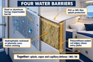
Shipyards demand strict insulation, but sometimes your panels fail sea trials. Thermal bridging secretly destroys panel efficiency. Let me show you how to fix these hidden heat leaks.
Thermal bridging drastically reduces effective insulation by creating highly conductive paths through metal fasteners and profiles. This degrades the nominal U-value of marine accommodation panels by 15% to 40%, increasing HVAC energy costs and causing condensation issues that fail maritime inspection standards.
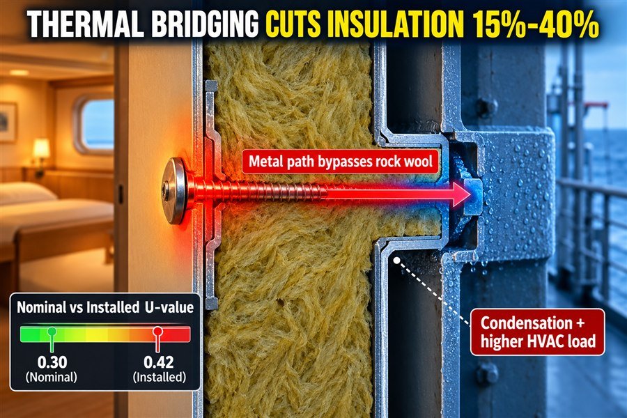
You buy certified panels, but the real-world performance drops once installed. This costs you money and harms your reputation with big shipyards. Let us explore exactly why this happens and how to protect your project margins.
Why Is a Marine Interior Panel's Installed U-Value Lower Than Its Nominal Value?
You pay for premium insulation ratings, but the installed performance is much worse. This gap causes failed shipyard inspections. Here is the exact reason this happens.
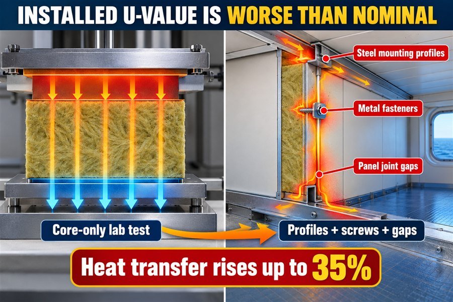
A marine interior panel's installed U-value drops below its nominal value because laboratory tests measure only the core material, ignoring the three main real-world heat leaks: steel mounting profiles, metal fasteners, and panel joint gaps, which together increase heat transfer by up to 35%.
Understanding the Gap Between Laboratory Panel Tests and Shipyard Reality
When I worked at the marine outfitting factory, I saw many buyers make a costly mistake. They read the product catalog, saw a very low U-value, and placed a big order. But the catalog number is just the "nominal" U-value. The factory tests this number in a laboratory using the ISO 8301 standard. In this test, they only measure the pure rockwool core in the middle of the panel. They do not test the edges. They do not test the installation parts.
When you install the panel on a ship, the situation changes completely. The real-world performance is called the "installed" U-value. Shipyards in Europe and the United States care about this installed value. If the installed value is too high, the ship's air conditioning system must work harder1. This burns more fuel and costs the ship owner a lot of money. The difference between the lab test and the real ship happens because of thermal bridging. Thermal bridging means heat finds a fast, easy way to travel through the wall, skipping the insulation entirely.
The Three Main Sources of Installed Heat Leaks
To control your quality and pass shipyard inspections, you must understand the three specific heat leaks that lower the U-value.
First, there are steel mounting profiles. We use steel tracks to hold the panels to the deck and ceiling. Steel conducts heat very fast. When heat hits the steel track, it travels straight into the cabin. Second, we use metal fasteners like screws and rivets. A single screw goes from the hot side of the panel, right through the rockwool, to the cold side. This acts like a tiny heat highway. Third, there are panel joint gaps. Even with good installation, tiny gaps remain where two panels meet. Air moves through these gaps, carrying heat with it. You must account for all three leaks when you buy materials.
| Heat Leak Source | Description | Impact on Total U-Value | Average Heat Transfer Increase |
|---|---|---|---|
| Steel Mounting Profiles | Continuous metal tracks at the floor and ceiling | Severe | 15% to 20%2 |
| Metal Fasteners | Screws and rivets piercing the panel core | Moderate | 5% to 10% |
| Panel Joint Gaps | Micro-spaces between connected panels | Minor to Moderate | 2% to 5% |
How Do Fasteners and Profiles Degrade Marine Bulkhead Insulation?
Metal parts are necessary for strength, but they ruin your insulation. These small steel pieces act as thermal highways. Let us look at their exact impact.
Fasteners and profiles degrade bulkhead insulation through two primary mechanisms: steel screws bypass the rockwool core, and continuous steel edge profiles create uninterrupted thermal shortcuts. These two mechanisms multiply local heat transfer by a factor of 10 to 50 compared to the insulation itself.
Mechanism of Heat Transfer Through Steel Panel Screws
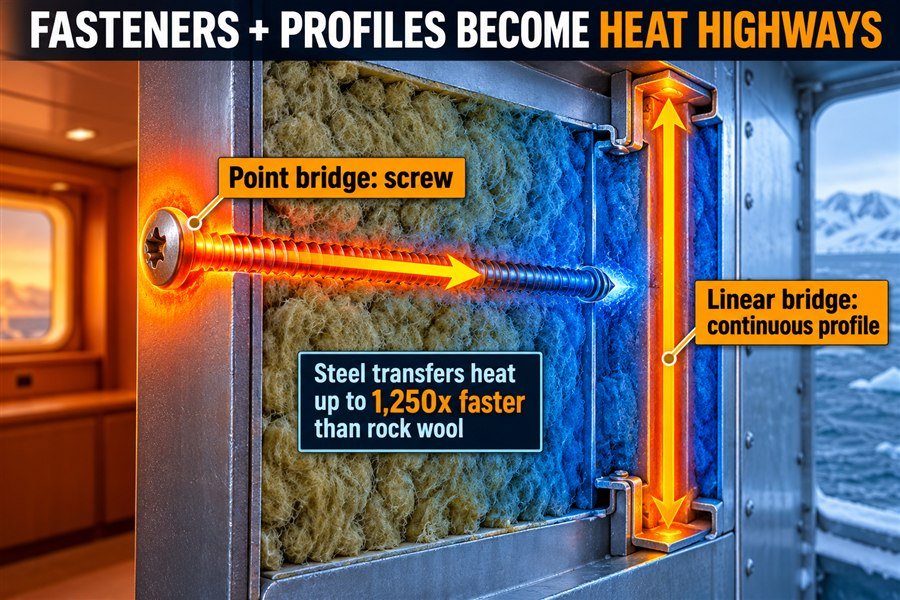
When you buy panels for a shipyard project, you want to keep costs low. But you must also ensure the technical details are correct. One major detail is the fasteners. Steel screws physically bypass the rockwool core. To understand this, we must look at thermal conductivity values. Rockwool has a thermal conductivity of about 0.04 W/(mK). Carbon steel has a thermal conductivity of about 50 W/(mK). This means steel transfers heat 1,250 times faster than rockwool.3
When a worker drives a screw through a 50mm marine panel, they create a perfect bridge. The heat does not try to push through the 50mm of rockwool. Instead, it finds the screw. The heat enters the head of the screw and travels down the metal shaft instantly. We call this a "point thermal bridge." Even though a screw is very small, a standard marine cabin uses hundreds of screws. When you add all these point bridges together, they destroy the insulation quality of your expensive panels.
Impact of Continuous Steel Edge Profiles on Bulkheads
Screws are bad, but continuous steel edge profiles are much worse. We call these "linear thermal bridges." Every marine accommodation panel needs a frame to give it strength. Usually, this frame is made of folded galvanized steel. Because the profile runs along the entire edge of the panel, it creates an uninterrupted thermal shortcut.
For example, a standard 2.4-meter high panel has 4.8 meters of vertical steel edges. When two panels lock together, the steel edges touch. This creates a solid wall of steel from the hot side to the cold side. Heat flows freely through this joint. This is why you often see condensation or water drops forming exactly on the panel joints in a cold room. The edge profiles are completely bypassing your high-quality rockwool. To solve this, you should look for suppliers in Asia who offer panels with thermal break profiles. A thermal break uses a piece of PVC or rubber inside the steel joint to stop the heat.
| Material | Thermal Conductivity (W/mK) | Heat Transfer Speed vs Rockwool | Bridge Type |
|---|---|---|---|
| Marine Rockwool (Core) | 0.04 | 1x (Baseline) | None |
| PVC (Thermal Break) | 0.19 | 4.7x | None |
| Carbon Steel (Screws) | 50.00 | 1,250x | Point Bridge |
| Aluminum (Profiles) | 205.00 | 5,125x | Linear Bridge |
How Is a Marine Interior Panel's U-Value Calculated With Thermal Bridges?
Guessing insulation values leads to rejected projects. You need exact calculations to satisfy shipyard engineers. Here is how we calculate the real numbers.
Calculating a marine panel's real U-value requires adding three specific elements: the nominal core U-value, the point thermal transmittance from individual fasteners (Chi-value), and the linear thermal transmittance from panel joints and profiles (Psi-value), according to the ISO 10211 calculation standard.
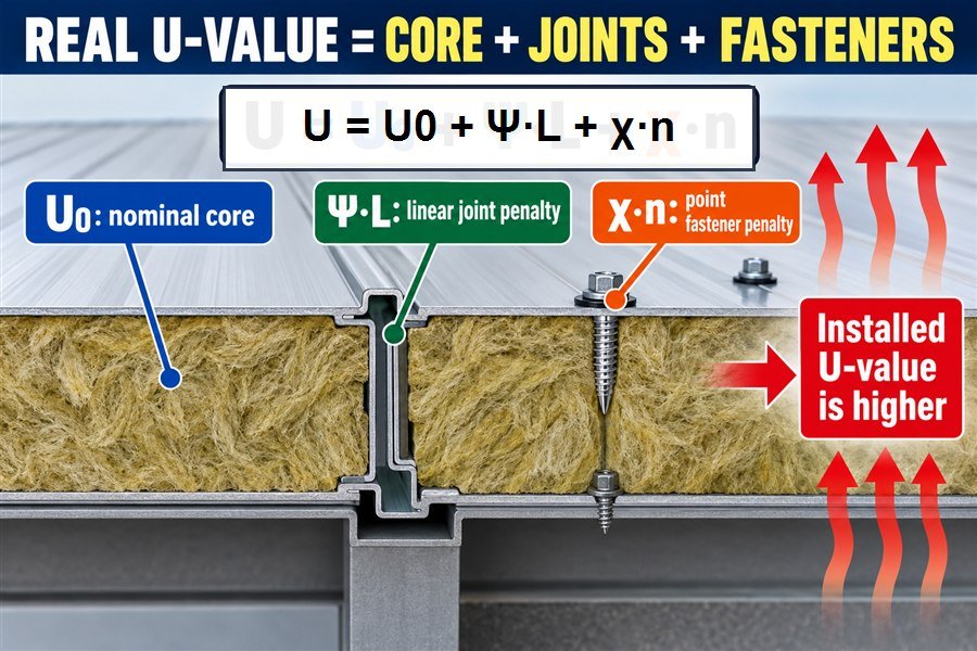
Applying the ISO 10211 Standard for Marine Panel Calculations
In my daily work helping clients, I often see procurement officers argue with shipyard engineers about insulation values. The shipyard engineer always wins because they use proper math. To sell successfully to strict European and American shipyards, you must show them you know how to calculate the real U-value. The global standard for this is ISO 10211.4
This standard says you cannot just use the factory catalog number. You must use a specific mathematical formula to find the total heat loss. The formula is U = U₀ + Σ(Ψ · L) + Σ(χ · n). In this formula, the U₀ is the nominal core U-value. This is the base number from the pure rockwool test. If you stop here, your calculation is wrong. You must add the next two elements to get the true, higher U-value. A higher U-value means worse insulation.
Adding Point Transmittance and Linear Transmittance Penalties
The second element in the calculation is the point thermal transmittance. In engineering, we call this the Chi-value (χ). This number measures the heat lost through single points, like fasteners and screws. You take the Chi-value of one screw and multiply it by the total number of screws (n).
The third element is the linear thermal transmittance. We call this the Psi-value (Ψ). This number measures the heat lost along straight lines, like panel joints, floor tracks, and ceiling profiles. You take the Psi-value of the joint and multiply it by the total length of the joint (L).
When you add the core value, the screw penalty, and the joint penalty together, you get the final installed U-value. If your final number is too high, the shipyard will reject the panels. By calculating this early, you can tell your factory in China or Vietnam to add better thermal breaks before production starts.
| Calculation Element | Symbol | Source of Heat Loss | Example Value |
|---|---|---|---|
| Nominal Core U-value | U₀ | Pure Rockwool Core | 0.60 W/(m²K) |
| Linear Transmittance | Ψ | Panel joints and edge profiles | + 0.15 W/(m²K) |
| Point Transmittance | χ | Screws and metal fasteners | + 0.05 W/(m²K) |
| Total Installed U-value | U | Combined System Performance | 0.80 W/(m²K) |
Why Doesn't Rockwool Guarantee Real-World Insulation in Marine Bulkheads?
You buy the best A-60 rockwool, but the cabin is still cold. High-quality rockwool alone cannot solve system-level flaws. Here is why the core material is not enough.
Rockwool cannot guarantee real-world insulation because its performance is entirely dependent on three installation factors: the density compression during mounting, the presence of internal air cavities, and the degree of moisture absorption, all of which can ruin the thermal resistance of even premium marine rockwool.
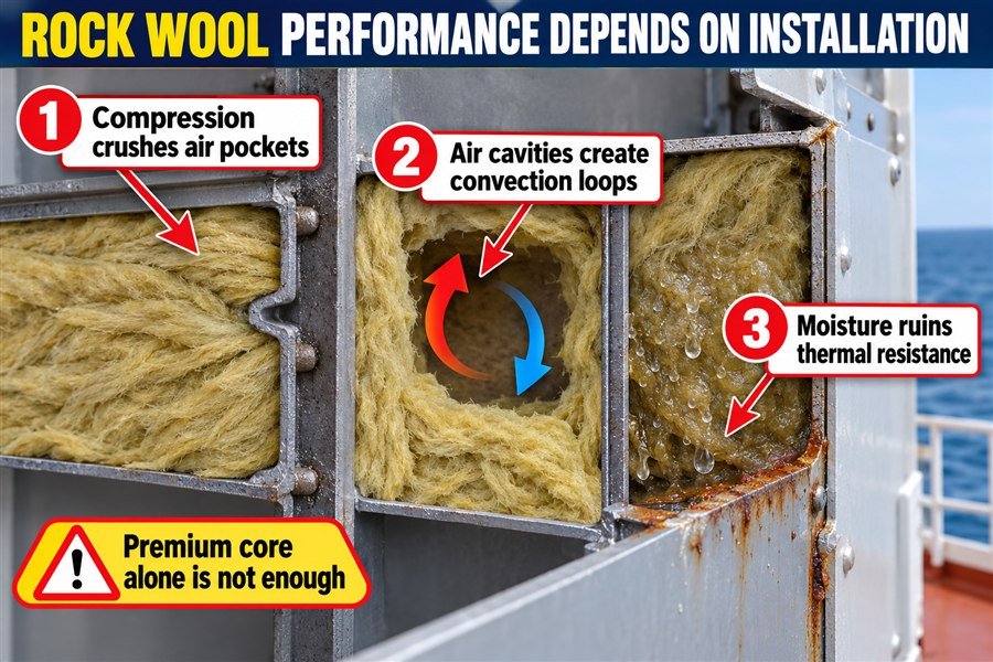
How Density Compression and Air Cavities Alter Rockwool Efficiency
Many people think that buying heavy rockwool solves all heat problems. Standard marine rockwool has a density of 120 to 150 kg/m3. But rockwool does not stop heat by itself. It stops heat by trapping millions of tiny pockets of still air inside its fibers.5 If you destroy these air pockets, the insulation fails.
This brings us to the first factor: density compression during mounting. When workers at the shipyard install panels, they sometimes squeeze the rockwool too hard to make it fit into the steel profiles. This compression crushes the tiny air pockets. Without the still air, the rockwool conducts heat much faster.
The second factor is internal air cavities. This happens when workers cut the rockwool too small. They leave empty spaces inside the bulkhead. Empty space is bad. The air inside the empty space will start to move in a circle, carrying hot air up and cold air down. We call this convection. Convection moves heat across the wall very quickly, making the rockwool completely useless in that area.
The Devastating Effect of Moisture Absorption on Marine Insulation
The third and most dangerous factor is the degree of moisture absorption. Ships operate in very wet environments. During the construction phase, cabins are often open to sea air, rain, or high humidity. Rockwool is like a sponge; it loves to drink water.
Water is a terrible insulator. The thermal conductivity of water is about 0.6 W/(mK), which is 15 times worse than dry rockwool.6 If your premium rockwool absorbs even a small amount of moisture, its U-value gets ruined immediately. Furthermore, wet rockwool touching steel panels causes rust from the inside out. I always advise my clients to ensure the factory seals the panel edges tightly and uses moisture-resistant rockwool. You must strictly control the logistics and storage of the panels to keep them dry before installation.
| Installation Factor | Cause of Failure | Impact on Insulation Performance | Resulting Defect |
|---|---|---|---|
| Density Compression | Workers forcing rockwool into tight profiles | Loses 10% to 20% efficiency | Crushed air pockets |
| Internal Air Cavities | Rockwool cut too small for the space | Loses 15% to 30% efficiency | Convection heat loops |
| Moisture Absorption | Poor storage or open cabins during build | Loses 50% to 80% efficiency | Wet fibers and internal rust |
How Much Thermal Performance Is Lost at Marine Lining Interfaces?
The edges of your lining panels are weak spots. You lose massive amounts of energy right where panels meet. Let us measure this exact loss.
Marine lining interfaces lose thermal performance across three specific junction types: panel-to-panel joints lose 10% to 15%, panel-to-deck connections lose 20%, and panel-to-ceiling corners lose up to 25%, resulting in a massive cumulative energy drain if not properly isolated.
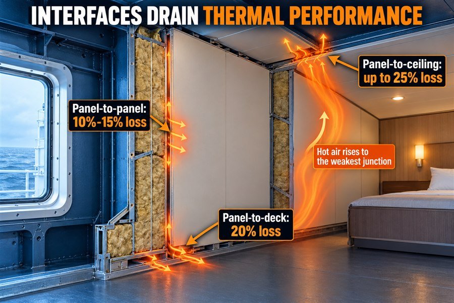
Measuring Heat Loss at Panel-to-Panel and Panel-to-Deck Connections
When you plan a cabin decoration project, you must look at the borders of the room. The interfaces where panels connect are the biggest thermal bridges. We can break these down into three specific junction types.
The first is panel-to-panel joints. These are the vertical lines where two wall panels lock together. Because the steel skins touch each other, heat leaks through. According to marine HVAC testing, these vertical joints cause a 10% to 15% loss in thermal performance compared to the center of the panel7.
The second junction type is panel-to-deck connections. This is the bottom edge where the wall meets the floor. This connection is much worse than vertical joints. To meet ship safety rules, the bottom track is usually made of thick steel and welded directly to the ship's main steel deck8. The ship's deck touches the cold seawater outside. Heat travels from the warm cabin, down the wall panel, into the steel track, and straight out to the sea. This connection alone causes about a 20% loss in thermal performance.
Managing High Thermal Drains at Panel-to-Ceiling Corners
The third junction type is the panel-to-ceiling corners. This is where the top of the wall meets the ceiling panels. This is the most critical area for heat loss, causing up to a 25% drop in performance9.
Why is the ceiling corner the worst? It is simple physics. Hot air always rises. In a ship cabin, the warmest air sits right at the ceiling level. This hot air constantly pushes against the top corners of the room. Because there is heavy steel framework in these corners to support the ceiling weight, the hot air finds an easy thermal bridge. The heat escapes rapidly into the void space above the ceiling. To fix this, you must demand that your suppliers provide specialized insulating tapes or rubber isolation strips for all ceiling U-profiles.
| Junction Type | Location | Typical Thermal Loss | Primary Reason for Heat Loss |
|---|---|---|---|
| Panel-to-Panel | Vertical wall joints | 10% to 15% | Metal skins touching at the lock |
| Panel-to-Deck | Floor tracks | 20% | Heavy steel tracks welded to cold deck |
| Panel-to-Ceiling | Top corners | 25% | Rising hot air meeting structural steel |
How Do Thermal Bridge Penalties Compare Across B-15/A-60 Marine Interior Connections?
Different fire ratings require different amounts of steel. You might overspend on HVAC if you treat B-15 and A-60 the same. Here is the exact comparison.
Thermal bridge penalties differ greatly between fire ratings: B-15 connections suffer a moderate 10% to 20% penalty due to lighter steel profiles, whereas A-60 connections endure a severe 30% to 45% penalty because of the heavy, continuous steel structural reinforcements required by IMO fire safety codes.
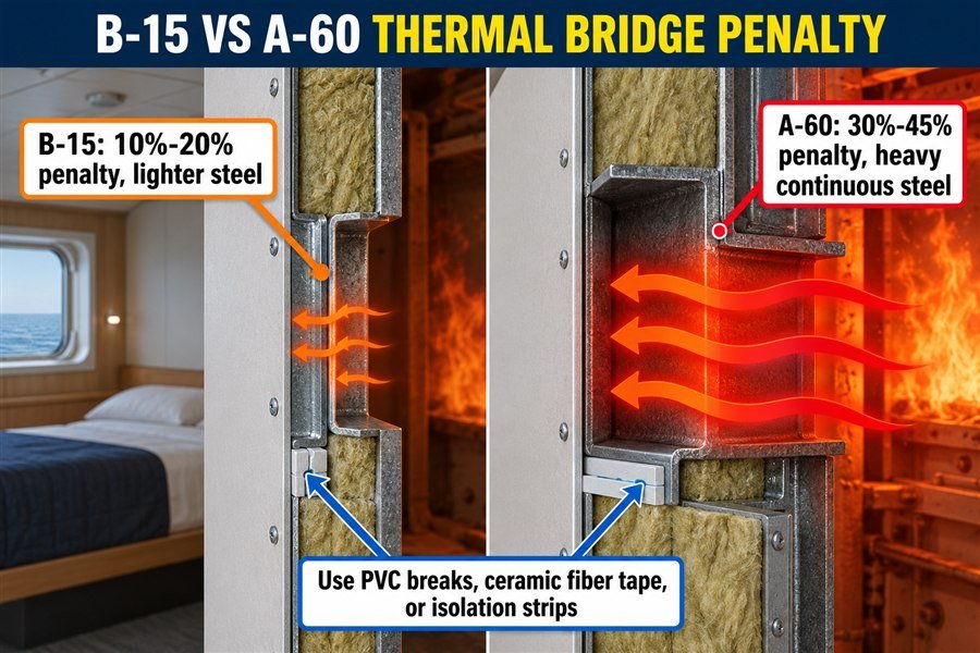
Analyzing the Moderate Thermal Penalties of B-15 Panel Connections
When you buy products for ship interiors, you deal with different fire classes. The two most common are B-15 and A-60. They perform very differently when it comes to thermal bridging.
Let us start with B-15 connections. B-Class panels are mostly used for cabin partitions to separate passenger rooms. According to maritime rules, they only need to stop fire for 15 minutes. Because the safety requirement is lower, the factories use thinner steel. A typical B-15 panel uses a 0.6mm galvanized steel skin and lightweight connection profiles. Because the steel is thin, there is less metal to conduct heat. As a result, B-15 connections suffer a moderate 10% to 20% penalty in their U-value. The thermal bridge is small, so the heat loss is manageable. You do not need extreme insulation measures for these standard cabin walls.
Understanding the Severe Thermal Bridging in A-60 Structural Reinforcements
A-60 connections are a completely different story. A-Class bulkheads separate high-risk areas, like the engine room, from passenger areas. The International Maritime Organization (IMO) FTP Code strictly regulates these walls. They must stop a severe fire for 60 full minutes.
To achieve this, the factory must use heavy, continuous steel structural reinforcements. The profiles holding an A-60 panel are often 1.5mm to 3.0mm thick. This massive amount of solid steel creates a giant thermal bridge. Heat flows through this thick steel very quickly. Because of this, A-60 connections endure a severe 30% to 45% penalty on their insulation value10. If a shipyard asks you to supply A-60 panels, you must warn them about this penalty. You will need to buy special thermal barrier tapes or request ceramic fiber isolation from your factory to reduce this massive heat drain.
| Fire Rating | Panel Application | Steel Profile Thickness | Bridge Penalty | Required Mitigation |
|---|---|---|---|---|
| B-15 | Standard Cabin Partitions | 0.6mm to 1.0mm | 10% to 20% | Standard PVC thermal break |
| A-60 | Engine Rooms / Stairwells | 1.5mm to 3.0mm | 30% to 45% | Ceramic fiber tape isolation |
Conclusion
Thermal bridging silently ruins marine panel insulation. By understanding the true U-value, fasteners, interfaces, and fire rating differences, you can secure better materials and protect your shipyard project profits.
-
"Performance-Based Building System Evaluation for DOE ...", https://buildingenergyscore.energy.gov/resources/download?key=publications%2Fsystem_evaluation.pdf. Heat-transfer and building-energy references generally show that higher envelope U-values increase conductive heat gain or loss, which raises cooling or heating loads that mechanical systems must meet. Evidence role: mechanism; source type: government. Supports: A higher installed U-value increases the load on the ship’s air-conditioning system.. Scope note: Most neutral sources discuss buildings rather than ships, so the support is contextual unless a marine HVAC or ship-energy source is used. ↩
-
"Thermal bridging and its mitigation in bamboo panel ...", https://bioresources.cnr.ncsu.edu/resources/thermal-bridging-and-its-mitigation-in-bamboo-panel-construction-with-steel-frameworks-and-mineral-wool-insulation/. Studies of thermal bridges in insulated envelope assemblies show that continuous metal framing or penetrations can substantially increase effective heat transfer compared with the nominal insulation value. Evidence role: statistic; source type: paper. Supports: Continuous steel mounting profiles can increase total heat transfer by about 15% to 20%.. Scope note: A source may support the direction and magnitude of thermal-bridge effects generally, but the exact 15%–20% value should be treated as assembly-specific unless the study evaluates comparable marine panel profiles. ↩
-
"List of thermal conductivities", https://en.wikipedia.org/wiki/List_of_thermal_conductivities. Using representative conductivity values of approximately 50 W/(m·K) for carbon steel and 0.04 W/(m·K) for mineral wool gives a ratio of about 1,250, supporting the stated comparative heat-conduction potential. Evidence role: mechanism; source type: education. Supports: Steel transfers heat about 1,250 times faster than rockwool based on the listed conductivity values.. Scope note: The ratio compares material conductivity only; actual heat flow through an installed screw also depends on geometry, contact resistance, temperature gradient, and surrounding assembly design. ↩
-
"An AI-based approach to thermal bridge analysis - PMC", https://pmc.ncbi.nlm.nih.gov/articles/PMC12378188/. ISO 10211 specifies methods for calculating heat flows and surface temperatures at thermal bridges, providing a recognized framework for evaluating non-uniform heat transfer in building components. Evidence role: definition; source type: institution. Supports: ISO 10211 is the relevant standard for calculating real U-values when thermal bridges are present.. Scope note: The standard is primarily framed for building construction; its use for marine panels should be understood as an engineering reference unless a marine specification explicitly requires it. ↩
-
"Moisture Durability with Vapor-Permeable Insulating ...", http://apps1.eere.energy.gov/buildings/publications/pdfs/building_america/moisture_durability_insulating_sheathing.pdf. Building-science and materials references explain that fibrous insulations such as mineral wool reduce heat transfer primarily by immobilizing air within a fiber matrix, which lowers convective and conductive heat flow through the material. Evidence role: mechanism; source type: education. Supports: Rockwool resists heat flow mainly by trapping still air in its fibrous structure.. Scope note: The source would explain the general heat-transfer mechanism of fibrous insulation and may not address the specific marine installation context. ↩
-
"Standard Reference Data for the Thermal Conductivity of ...", https://www.nist.gov/document/jpcrd493pdf. Reference data list liquid water’s thermal conductivity near room temperature at approximately 0.6 W/m·K, while mineral-wool insulation is commonly reported around 0.035–0.045 W/m·K, supporting the order-of-magnitude comparison between wet and dry insulation media. Evidence role: statistic; source type: government. Supports: Water has a thermal conductivity of about 0.6 W/(mK), far higher than that of dry rockwool insulation.. Scope note: The comparison uses typical room-temperature values; actual conductivity varies with temperature, mineral-wool product, density, and moisture distribution within the insulation. ↩
-
"What Thermal Conductivity Pitfalls Hide in Marine ...", https://magellanmarinetech.com/what-thermal-conductivity-pitfalls-hide-in-marine-accommodation-panel-specs/. A building-physics or marine accommodation HVAC test report should support that metal-faced panel joints have lower thermal resistance than the panel field and, if available, quantify the reported 10–15% reduction relative to center-panel performance. Evidence role: statistic; source type: paper. Supports: Vertical panel-to-panel joints cause a 10% to 15% loss in thermal performance compared with the center of the panel.. Scope note: The exact percentage may depend on panel construction, joint geometry, insulation material, and test method. ↩
-
"How to choose the right marine wall panels for marine interior ...", https://magellanmarinetech.com/how-choose-right-marine-wall-panels-for-marine-interior-projects/. A ship-construction standard, classification-society document, or marine accommodation design reference should substantiate the use of steel floor tracks or welded steel connections at cabin bulkhead-to-deck interfaces for structural and fire-safety reasons. Evidence role: general_support; source type: institution. Supports: Panel-to-deck connections commonly use substantial steel tracks welded to the ship’s steel deck to satisfy ship safety and construction requirements.. Scope note: Such sources may establish common construction practice without proving that every vessel uses the same track thickness or welding detail. ↩
-
"Thermal Bridges", https://web.ornl.gov/sci/buildings/2016/docs/presentations/workshops/workshop-3/Workshop3_Bossche.pdf. A heat-transfer or HVAC study on ceiling-wall junction thermal bridges should support that ceiling corners can produce substantial reductions in effective envelope performance; direct support would require data showing losses up to about 25% for comparable marine cabin assemblies. Evidence role: statistic; source type: paper. Supports: Panel-to-ceiling corners can cause up to a 25% drop in thermal performance.. Scope note: General thermal-bridge literature can support the importance of ceiling-wall junctions, but may not directly verify the 25% figure for ship cabins. ↩
-
"Envelope Performance and Thermal Bridge Derating", https://www.mass.gov/doc/envelope-and-thermal-bridge-derating-section/download. Thermal-bridge research on metal-framed insulated assemblies shows that continuous steel members can substantially increase effective thermal transmittance compared with the clear-field insulation value. Evidence role: mechanism; source type: paper. Supports: Heavy continuous steel reinforcements in A-60 panel connections can significantly reduce effective insulation performance.. Scope note: Such studies support the mechanism and possible scale of metal thermal bridging, but a 30%–45% penalty for A-60 ship-panel connections would require assembly-specific test data or thermal modeling. ↩