Cold spots on ship walls ruin passenger comfort and cause fast rusting. I see many buyers ignore panel connections. You must evaluate thermal bridging to protect your ship's interior quality.
To evaluate thermal bridging in marine accommodation panels, you must inspect joining profiles, insulation gaps, and metal-to-metal contacts. Evaluating these elements requires checking detailed cross-section drawings, calculating the effective U-value difference, and verifying the physical installation of thermal breaks between the cold steel deck and the warm cabin interior.
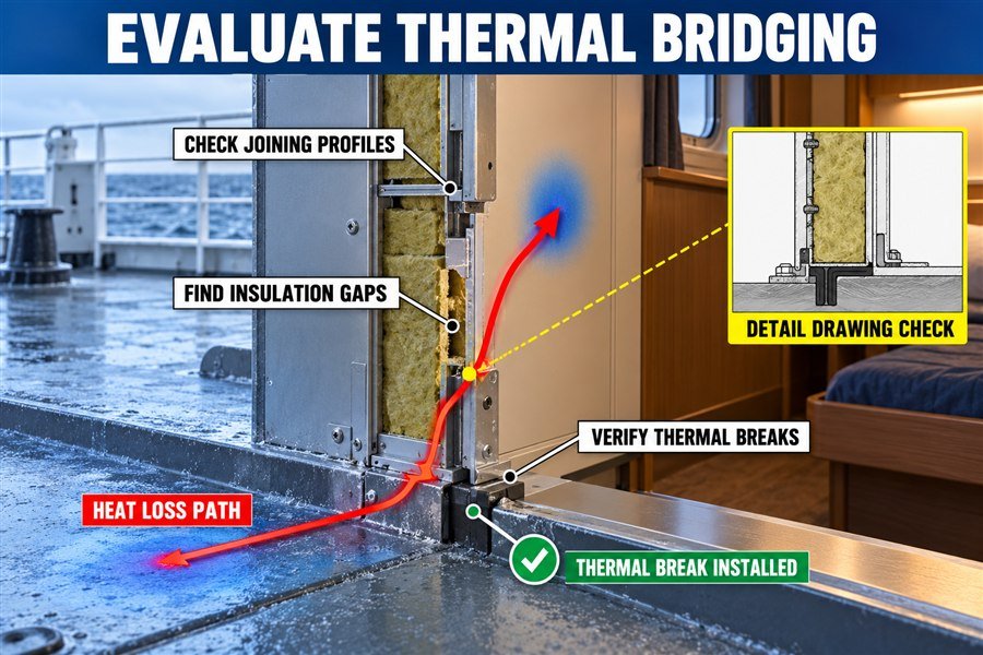
I will walk you through the exact steps to check your interior outfitting panels so you can stop heat loss and control your project budget.
Which Drawings Reveal Thermal Bridging Risks in Marine Interior Panels?
Missing thermal details on drawings leads to expensive shipyard rework. You cannot guess how panels connect. You need the right drawings to spot thermal bridges before you buy.
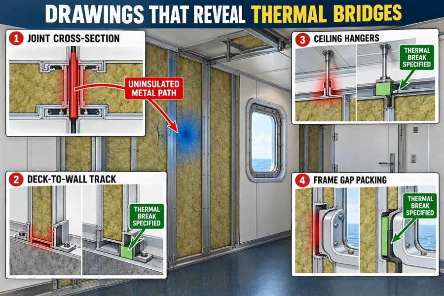
Four specific drawings reveal thermal bridging risks in marine interior panels: cross-sectional joint details showing panel connections, deck-to-wall interface plans detailing base tracks, ceiling suspension plans showing metal hangers, and window/door frame sections highlighting steel boundaries. You must review all four to identify uninsulated metal paths.
Analyzing Cross-Sectional Joint and Deck-to-Wall Interface Drawings
I always ask suppliers for cross-sectional joint details first. These drawings show exactly how two marine wall panels connect. A standard 50mm rockwool panel might have an excellent thermal rating. However, if the joint uses a solid steel spline without a PVC thermal break, heat will rush right through that metal. According to ISO 7547 standards for marine HVAC calculations, a solid steel bridge can increase local heat transfer by over 300%1. You must find the PVC thermal block in the drawing. Next, I check the deck-to-wall interface plans. These plans show the base tracks. The ship's steel deck gets very cold during winter voyages. If the panel sits directly in a galvanized steel bottom profile (usually 1.2mm thick) without a 3mm to 5mm rubber or ceramic tape barrier, the cold transfers straight up the panel face. Condensation will quickly form here. This destroys the panel's surface film.
Examining Ceiling Suspension Plans and Frame Sections
Then, I move on to ceiling suspension plans. A marine ceiling panel hangs from the deck above using metal hangers. These hangers act as heat highways2. The drawings must show a thermal break, like a 5mm thick rubber isolation pad, between the hanger bracket and the ship's steel structure. If the drawing just shows direct welding or direct bolting, you have a massive thermal bypass. I reject those designs immediately. Finally, I review the window and door frame sections. A B-15 marine fire door or a heavy window frame is set into a rigid steel boundary. The gap between the door frame and the wall panel is a prime risk area. I look for drawings that specify stuffing the 10mm to 15mm gap with 110 kg/m3 density rockwool3. A drawing that leaves this gap empty is a major failure.
| Drawing Type | What It Shows | Thermal Bridge Risk | Required Specification |
|---|---|---|---|
| Cross-Sectional Joint Detail | Panel-to-panel connection | Solid steel spline conducting heat | Rigid PVC thermal break block |
| Deck-to-Wall Interface | Panel sitting in base track | Cold deck touching steel track | 3mm to 5mm rubber/ceramic tape |
| Ceiling Suspension Plan | Hanger brackets | Metal hanger bolted to cold deck | 5mm thick rubber isolation pad |
| Window/Door Frame Section | Gap between panel and frame | Empty void causing cold drafts | 110 kg/m3 density rockwool packing |
How to Assess Effective vs. Nominal Marine Interior Insulation?
Suppliers often quote amazing insulation numbers, but real-world ship cabins still feel cold. Buying based on nominal numbers causes comfort failures. You must calculate the actual effective insulation value.
To assess effective versus nominal marine interior insulation, you must compare the core material's stated U-value against the installed panel's U-value, factoring in three specific losses: structural framing penetrations, panel joint heat leaks, and moisture accumulation. Combining these three factors gives you the true effective insulation performance.
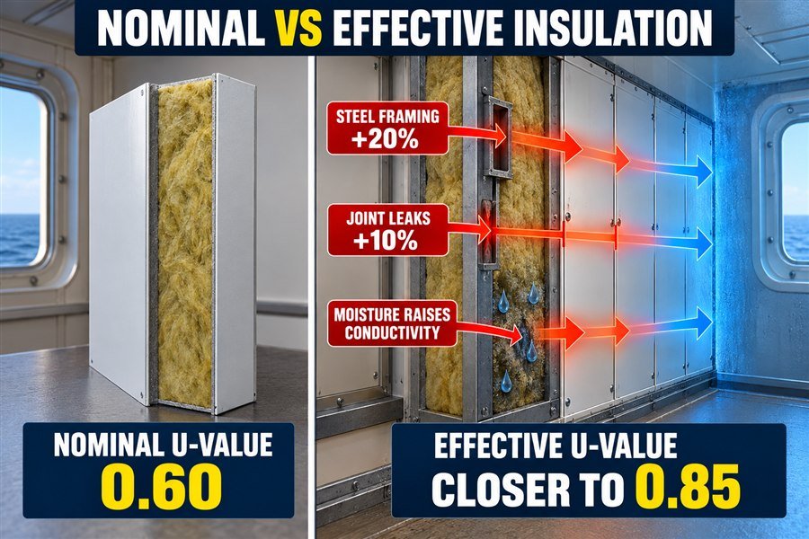
Calculating Losses from Structural Framing Penetrations and Panel Joints
I learned early on that a nominal U-value is just a laboratory number. A supplier might quote a nominal U-value of 0.60 W/(m2·K) for a 50mm marine wall panel. However, the effective U-value is always worse. You must factor in structural framing penetrations. Panels are held by steel profiles. The Society of Naval Architects and Marine Engineers (SNAME) notes that metal framing can reduce overall insulation effectiveness by 15% to 20%. I always add this 20% penalty to the nominal value. Next, I calculate panel joint heat leaks. A typical cabin uses many 600mm wide panels. Every 600mm, there is a joint. If these joints lack proper thermal breaks, they act as cooling fins. A standard 2.4-meter high panel will have 2.4 meters of joint edge. I estimate that poor joint design degrades the panel's thermal performance by another 10%4. You cannot ignore these joints when sizing your HVAC system.
Adjusting for Moisture Accumulation Over Time
Finally, I adjust for moisture accumulation. Marine environments are very humid. Even with good vapor barriers, some moisture enters the rockwool core over time. According to ASHRAE marine guidelines, just a 1% increase in moisture content by volume can increase the thermal conductivity of rockwool by up to 5%. Over a 5-year period, this means your effective insulation value gets much worse. When I buy marine ceiling panels or wall panels from Asia, I ask for the water absorption test report. The core material should absorb less than 1 kg/m2 of water. When you combine the framing losses, joint leaks, and moisture factors, a panel with a nominal U-value of 0.60 W/(m2·K) often has an effective U-value closer to 0.85 W/(m2·K). I use this higher number to guarantee passenger comfort.
| Loss Factor | Source of Heat Leak | Impact on Nominal U-Value | How to Mitigate |
|---|---|---|---|
| Framing Penetrations | Steel profiles and tracks | 15% to 20% penalty | Use thermal isolation pads at mounts |
| Panel Joints | 600mm panel connections | 10% penalty | Use PVC thermal breaks in splines |
| Moisture Accumulation | Humidity entering rockwool | Up to 5% penalty per 1% moisture | Specify water absorption < 1 kg/m2 |
Which Structural Drawings Confirm Marine Interior Insulation Continuity?
A small gap in insulation causes huge condensation problems on a ship. Guessing about insulation coverage is a costly mistake. You need specific structural drawings to prove absolute continuity.
Three structural drawings confirm marine interior insulation continuity: bulkhead intersection drawings showing continuous mineral wool packing, deck penetration details indicating insulated pipe collars, and corner detail plans revealing overlapping insulation layers. Reviewing these three specific structural drawings ensures no bare steel is exposed to warm cabin air.
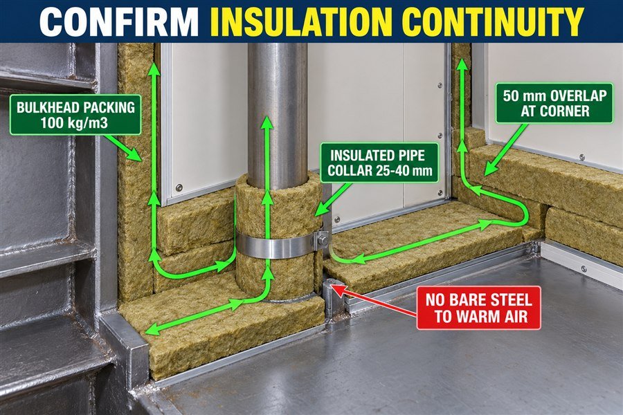
Verifying Bulkhead Intersection Drawings and Deck Penetration Details
I rely heavily on structural drawings to stop cold spots. The first drawing you must demand is the bulkhead intersection drawing. This shows where interior panels meet the main steel ship structure. You want to see continuous mineral wool packing at these T-joints. The International Maritime Organization (IMO) SOLAS regulations require fire integrity here, but I also look for thermal integrity. The drawing must specify packing the gap with 100 kg/m3 rockwool5. If it just shows an empty void, the cold steel will chill the cabin air. The second crucial document is the deck penetration detail drawing. Pipes and cables must pass through the steel deck and into the cabin ceiling space. The drawing must indicate insulated pipe collars. A bare steel pipe acts like a refrigerator coil. I expect to see 25mm to 40mm thick flexible elastomeric foam or rockwool wrapped around the pipe for at least 300mm above the deck level6.
Checking Corner Detail Plans for Overlapping Layers
The third vital drawing is the corner detail plan. Corners are notoriously bad for thermal bridging7 because the geometry forces panels to pull apart slightly. The corner detail plan must reveal overlapping insulation layers. I look for drawings that show a 90-degree steel inner corner piece backed by a continuous L-shaped rockwool batt. The rockwool should extend past the joint line by at least 50mm. I once dealt with a shipyard that skipped this detail. They just pushed two panels together at a corner without overlap. Within three months, condensation ruined the PVC film on the panels. To prevent this, your procurement team must ask the panel supplier to provide these three structural drawings before signing any contract. These details separate good suppliers from bad ones.
| Structural Drawing | Focus Area | Essential Detail to Find | Risk if Missing |
|---|---|---|---|
| Bulkhead Intersection | Panels meeting ship steel | 100 kg/m3 rockwool packing | Severe cold spots at walls |
| Deck Penetration | Pipes crossing the deck | 25mm to 40mm thick foam collars | Condensation dripping from pipes |
| Corner Detail Plan | 90-degree room corners | 50mm overlapping rockwool batts | Peeling PVC film in corners |
What Are Red Flags for Thermal Bypass in Marine Ceilings?
Cold drafts from the ceiling destroy the luxury feel of any ship cabin. Many buyers miss hidden ceiling flaws. You must spot thermal bypass red flags before installation begins.
Four major red flags indicate thermal bypass in marine ceilings: uninsulated light fixture housings, direct steel-to-steel hanger connections, missing perimeter edge sealing, and gaps around HVAC ventilation grilles. Spotting these four issues during the procurement and mock-up phase prevents massive heat loss through the cabin roof.
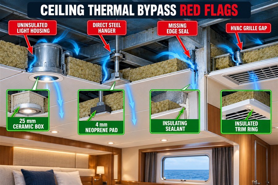
Identifying Uninsulated Light Housings and Direct Steel Hanger Connections
Ceiling spaces on ships are full of cold air because the steel deck above is exposed to the outside weather.8 The first red flag I look for is uninsulated light fixture housings. When you cut a hole in a marine ceiling panel for a downlight, you destroy the thermal barrier.9 I check the supplier's catalog to see if they offer insulated backing boxes for lights. These boxes must cover the back of the light with at least 25mm of ceramic wool. Without them, cabin heat flows straight up into the void. The second red flag is direct steel-to-steel hanger connections. Marine ceiling panels hang from galvanized steel suspension grids. If the hanger wire connects directly to the cold steel deck and directly to the ceiling panel rail, it creates a fast thermal bridge.10 The hanger system must include a rubber vibration and thermal isolator, usually a 4mm thick neoprene pad, to break the metal connection.
Spotting Missing Perimeter Sealing and HVAC Grille Gaps
The third red flag is missing perimeter edge sealing. Where the ceiling panel meets the wall panel, there is often a 5mm to 10mm tolerance gap. If the installation manual does not require filling this gap with a fire-rated, thermally insulating silicone sealant, cold air will wash down the walls. I always ensure my purchasing contracts include the correct sealant. The final red flag is gaps around HVAC ventilation grilles. The metal ductwork brings air into the cabin, but the space between the duct and the cut ceiling panel is a major leak point. A reliable supplier will provide custom-fit insulated trim rings. If I see a mock-up cabin where I can slide a piece of paper between the HVAC grille and the ceiling panel, I know severe thermal bypass is happening.11
| Ceiling Red Flag | Location | Consequence of Failure | Required Fix |
|---|---|---|---|
| Uninsulated Light Housings | Recessed downlights | Heat escapes up into ceiling void | 25mm ceramic wool backing boxes |
| Direct Steel Hangers | Suspension grid mounts | Cold transfers down from deck | 4mm thick neoprene isolation pads |
| Missing Perimeter Sealing | Ceiling-to-wall joints | Cold drafts wash down the walls | Fire-rated insulating silicone sealant |
| HVAC Grille Gaps | Air conditioning vents | Conditioned air leaks into voids | Custom-fit insulated trim rings |
How to Check Metal Interfaces for Thermal and Fire Integrity in Marine Interior Panels?
Metal joints can melt in a fire and freeze in the winter. Ignoring these interfaces puts passenger safety and comfort at huge risk. You must inspect metal connections rigorously.
To check metal interfaces for thermal and fire integrity in marine interior panels, you must evaluate three critical factors: the presence of intumescent strips for fire sealing, the use of PVC or rubber thermal break profiles, and the certification of heat-resistant steel fasteners. All three ensure complete joint performance.
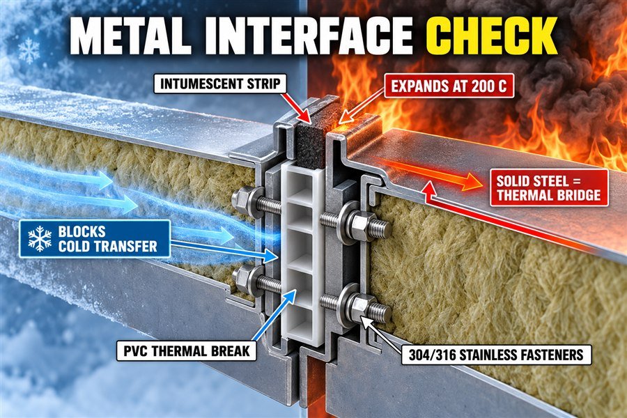
Evaluating Intumescent Strips and PVC Thermal Break Profiles
Metal interfaces are the weakest points in any marine outfitting system. I start by checking for the presence of intumescent strips. A marine fire door or a B-15 wall panel joint uses metal profiles. Under SOLAS fire testing (IMO FTP Code Part 3), the metal will warp at high temperatures. The interface must have a 2mm thick intumescent strip hidden in the joint. At 200°C, this strip expands to 10 times its size.12 This seals the gap against smoke and fire. I always ask the supplier for a close-up photo of the joint profile to confirm this strip exists. Next, I check for the use of PVC or rubber thermal break profiles. A common metal H-profile used to join two panels conducts heat very quickly13. A high-quality profile consists of two steel halves joined by a rigid PVC center block. This PVC block stops the cold from passing from one side to the other. If a supplier only offers solid one-piece steel profiles, I know the thermal integrity will fail.
Verifying Certification of Heat-Resistant Fasteners
Finally, I verify the certification of heat-resistant steel fasteners. The screws and rivets that hold the metal interfaces together must withstand both extreme cold and extreme heat. I check the material certificates. The fasteners should be made of 304 or 316 grade stainless steel14, not cheap zinc-plated carbon steel. Zinc-plated screws will rust quickly due to the condensation caused by thermal bridging. Also, in a fire, standard screws can shear off, causing the panel to collapse. I always require the supplier to list the fastener specifications on their Type Approval certificate. By checking the intumescent strips, the PVC thermal breaks, and the stainless steel fasteners, I can guarantee that the metal interface is completely secure.
| Interface Component | Thermal Function | Fire Function | Material Specification |
|---|---|---|---|
| Intumescent Strip | Fills minor tolerance gaps | Expands at 200°C to block smoke | 2mm thick expanding graphite |
| Thermal Break Profile | Stops cold transfer across joint | Maintains joint structure | Rigid PVC center block |
| Fasteners | Prevents rust from condensation | Holds panels together under extreme heat | 304 or 316 grade stainless steel |
How to Verify a Marine Interior Supplier Addresses Thermal Bridging?
Many suppliers talk about high quality but deliver poorly designed panels. Trusting sales pitches leads to failed inspections. You must use a strict verification process to qualify your suppliers.
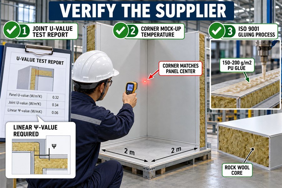
To verify a marine interior supplier addresses thermal bridging, you must execute three verification steps: demand a certified laboratory U-value test report for the panel joint, request a physical mock-up inspection of corner connections, and review the supplier's ISO 9001 quality manual regarding insulation core gluing processes.
Demanding Certified U-Value Test Reports and Physical Mock-Ups
When I buy from new factories in Asia, I do not just listen to the sales team. I follow a strict process. First, I demand a certified laboratory U-value test report specifically for the panel joint. Many suppliers will give you a test report for the center of the panel. That is useless for thermal bridging. I insist on an EN ISO 10456 or equivalent thermal test report that measures heat flow across the joined connection of two panels. The test result should clearly state the linear thermal transmittance (Ψ-value) of the joint. Second, I request a physical mock-up inspection of corner connections. Drawings are good, but seeing is believing. I ask the factory to build a 2-meter by 2-meter corner room. I bring an infrared thermometer to the factory. If they use a proper thermal break, the corner surface temperature should be identical to the center of the panel. If it is 2°C or 3°C colder, they have a thermal bridge problem.15
Reviewing the ISO 9001 Quality Manual for Gluing Processes
Third, I review the supplier's ISO 9001 quality manual regarding insulation core gluing processes. Thermal bridging can happen inside the panel if the rockwool core separates from the steel skin. This leaves an air gap where cold air circulates.16 The quality manual must state exactly how much polyurethane (PU) glue they use. The industry standard is 150 grams to 200 grams of PU glue per square meter. The manual must also define the pressing time, usually 20 to 30 minutes at a specific temperature. If the supplier cannot show me this written procedure, I know their quality control is weak. By checking the joint test report, inspecting the physical mock-up, and verifying the gluing process, I protect my company from buying cheap, defective marine panels.
| Verification Step | Action Required | Target Outcome |
|---|---|---|
| U-Value Test Report | Request EN ISO 10456 joint test | Obtain linear thermal transmittance (Ψ-value) |
| Physical Mock-Up | Measure corner temp with infrared | Corner temp matches panel center temp |
| ISO 9001 Manual Review | Check PU gluing procedures | Confirm 150-200 grams/m2 glue application |
Conclusion
By rigorously evaluating drawings, calculating effective insulation values, and verifying supplier mock-ups, you eliminate thermal bridging in marine panels, ensuring absolute comfort and long-term durability for every ship interior project.
-
"Methods for improving the thermal performance of ... - PMC - NIH", https://pmc.ncbi.nlm.nih.gov/articles/PMC11651610/. A finite-element or experimental thermal-bridge study showing that steel connectors through insulated assemblies can increase local heat flow several-fold would support the stated order of magnitude for comparable geometries. Evidence role: statistic; source type: paper. Supports: A solid steel bridge in an insulated marine wall joint can increase local heat transfer by over 300%.. Scope note: This would not prove that ISO 7547 itself gives the 300% figure, and the percentage may vary with spline size, insulation thickness, and boundary temperatures. ↩
-
"Status of NIST Thermal Insulation Reference - Materials", https://tsapps.nist.gov/publication/get_pdf.cfm?pub_id=861640. Reference data on thermal conductivity showing that steel conducts heat far more readily than mineral wool, rubber, or air would support the characterization of uninterrupted metal ceiling hangers as conductive thermal bridges. Evidence role: mechanism; source type: research. Supports: Metal ceiling hangers can create thermal bridges between the cold deck structure and the ceiling panel system.. Scope note: Material-property data support the heat-transfer mechanism but do not quantify heat loss for the exact hanger geometry described. ↩
-
"Door class B-15 - LUBMOR - PDF Catalogs | Documentation", https://pdf.nauticexpo.com/pdf/lubmor/door-class-b-15/31292-64611.html. Marine fire-test or classification documentation for B-15 door or bulkhead assemblies specifying mineral-wool packing around frame gaps would support the claim that dense rockwool is used to preserve fire and insulation performance at openings. Evidence role: case_reference; source type: institution. Supports: A 10 mm to 15 mm gap around a B-15 marine door or window frame may need specified dense rockwool packing, such as 110 kg/m3, to avoid performance failure.. Scope note: The exact 110 kg/m3 density is likely assembly- or approval-specific and should not be treated as a universal B-15 requirement unless the cited approval states it directly. ↩
-
"BUILDING RESEARCH TRANSLATION Weak thermal ...", https://www.govinfo.gov/content/pkg/GOVPUB-C13-68587dc9b5c1c38a21bbd6630b097cbb/pdf/GOVPUB-C13-68587dc9b5c1c38a21bbd6630b097cbb.pdf. Research on sandwich-panel and building-envelope joints shows that joints and splines can create linear thermal bridges that increase heat flow beyond the nominal panel U-value. Evidence role: mechanism; source type: paper. Supports: Poorly designed panel joints can degrade panel thermal performance by about 10%.. Scope note: A source may support the mechanism of joint-related thermal bridging, while the specific 10% degradation should be treated as design-specific unless directly measured for the same panel geometry. ↩
-
"60 (number)", https://en.wikipedia.org/wiki/60_(number). Marine fire-insulation approvals and classification documentation commonly identify mineral-wool insulation by density and thickness as part of an approved bulkhead or deck construction, supporting the need to specify a defined rockwool density in such details. Evidence role: general_support; source type: institution. Supports: Bulkhead intersection details should specify packing gaps with 100 kg/m3 rockwool rather than leaving an undefined void.. Scope note: This would support the practice of specifying density, but it may not prove that 100 kg/m3 is mandatory for every bulkhead intersection or every thermal-bridging condition. ↩
-
"Field Applications of Mechanical Insulation", https://smartenergy.illinois.edu/wp-content/uploads/2023/11/Field-Applications-of-Mechanical-Insulation.pdf. Mechanical-insulation guidance for condensation control treats pipe-insulation thickness as dependent on surface temperature, ambient humidity, and insulation properties, supporting the need for insulated collars on cold metal penetrations. Evidence role: mechanism; source type: institution. Supports: Deck penetration details should show insulated pipe collars, with 25-40 mm insulation extending at least 300 mm above deck level.. Scope note: Such guidance supports the condensation-control rationale, but the exact 25-40 mm thickness and 300 mm extension may need project-specific calculation or approval rather than a universal rule. ↩
-
"Statistical modelling of heat transfer for thermal bridges ...", https://www.sciencedirect.com/science/article/abs/pii/S0378778805000071. Thermal-bridge research describes corners as two- or three-dimensional heat-flow regions where heat loss and low interior surface temperatures can differ from flat assemblies, supporting the claim that corners are vulnerable thermal-bridge locations. Evidence role: mechanism; source type: paper. Supports: Corners are especially prone to thermal bridging because their geometry creates multidimensional heat flow and lower interior surface temperatures.. Scope note: Most thermal-bridge literature is based on buildings; it provides a transferable heat-transfer mechanism rather than direct evidence from ship cabin panel systems. ↩
-
"Moisture Control Guidance for Building Design, ...", https://www.epa.gov/sites/default/files/2014-08/documents/moisture-control.pdf. Guidance on ship accommodation insulation describes steel boundary surfaces exposed to external air or weather as requiring thermal insulation to limit heat transfer and condensation risk, supporting the premise that uninsulated deck-adjacent spaces can be cold. Evidence role: general_support; source type: institution. Supports: Ceiling voids below exposed steel decks on ships can be cold because the steel structure conducts heat to the external environment.. Scope note: The source would support the building-physics context rather than verify that all ship ceiling voids are cold in every vessel or climate. ↩
-
"Measure Guideline: Air Sealing Attics in Multifamily Buildings", https://www1.eere.energy.gov/buildings/publications/pdfs/building_america/measure_guide_air_sealing_attics.pdf. Building-envelope and insulation guidance identifies recessed luminaires and other ceiling penetrations as interruptions in insulation and air barriers that can increase heat loss or air leakage, which is analogous to the downlight opening described here. Evidence role: mechanism; source type: government. Supports: A recessed downlight opening can interrupt the continuity of a ceiling's thermal or air barrier.. Scope note: Most available neutral sources discuss buildings rather than marine ceiling panels, so the evidence is best used by analogy unless a marine-specific source is found. ↩
-
"NEW MATERIALS AND CONCEPTS TO REDUCE ...", https://web.ornl.gov/sci/buildings/conf-archive/1985%20B3%20papers/054.pdf. Technical references on thermal bridging explain that continuous metal elements penetrating or bypassing insulation provide high-conductivity heat-flow paths, supporting the claim that a direct steel hanger connection can act as a thermal bridge. Evidence role: mechanism; source type: education. Supports: A direct metal connection between a cold steel deck and an interior ceiling rail can create a thermal bridge.. Scope note: The source may describe thermal bridges in general construction rather than the exact shipboard hanger assembly. ↩
-
"Job Aid 19-1: Seal Ducts With Mastic", https://www.energy.gov/sites/default/files/2022-06/job-aid-19-1_seal-ducts-with-mastic.pdf. Air-sealing guidance for HVAC registers and ceiling penetrations notes that gaps around ducts, grilles, and other penetrations can permit leakage between conditioned spaces and cavities, supporting the conclusion that visible grille gaps indicate an air-bypass path. Evidence role: mechanism; source type: government. Supports: A visible gap around an HVAC grille can create an air leakage or thermal bypass path between the cabin and ceiling void.. Scope note: The evidence would support the presence and mechanism of bypass leakage, not quantify it as 'severe' without measurements from the specific mock-up. ↩
-
"The effect of 150μm expandable graphite on char ...", https://www.academia.edu/14476451/The_effect_of_150%CE%BCm_expandable_graphite_on_char_expansion_of_intumescent_fire_retardant_coating. Studies and technical references on expandable graphite intumescent materials report expansion beginning around 180-220°C and large volume increases during heating, which is consistent with the stated expansion behavior. Evidence role: mechanism; source type: paper. Supports: Expanding graphite intumescent strips can begin expanding at about 200°C and may increase many times in volume.. Scope note: Expansion temperature and ratio vary by graphite grade, binder, loading, and test method, so the source would contextualize rather than universally prove the exact 10× value. ↩
-
"properties of selected materials at cryogenic temperatures", https://tsapps.nist.gov/publication/get_pdf.cfm?pub_id=913059. Thermal-conductivity data show that steel has a much higher thermal conductivity than plastics such as rigid PVC, supporting the general assertion that an uninterrupted steel profile can act as a thermal bridge. Evidence role: mechanism; source type: research. Supports: A solid steel joining profile transfers heat more readily than a profile interrupted by a low-conductivity plastic thermal break.. Scope note: Material conductivity data do not by themselves prove the thermal performance of a specific H-profile assembly, which depends on geometry, contact conditions, and installation details. ↩
-
"Guide to the Selection and Use of High Performance ...", https://www.nrc.gov/docs/ML0334/ML033490048.pdf. Corrosion-resistance references for stainless steels describe grades 304 and 316 as austenitic stainless steels with substantially better general corrosion resistance than zinc-coated carbon steel, with 316 offering improved chloride resistance due to molybdenum. Evidence role: expert_consensus; source type: education. Supports: 304 or 316 stainless steel fasteners are more suitable than zinc-plated carbon steel where condensation and marine corrosion are concerns.. Scope note: This supports material selection for corrosion resistance in moist or marine-adjacent conditions, but actual fastener life also depends on coating quality, galvanic coupling, temperature, and maintenance. ↩
-
"Methods for improving the thermal performance of ... - PMC - NIH", https://pmc.ncbi.nlm.nih.gov/articles/PMC11651610/. Infrared thermography literature explains that thermal bridges often appear as localized surface-temperature anomalies, so a colder corner than the adjacent panel center can be evidence of a thermal bridge under stable test conditions. Evidence role: mechanism; source type: paper. Supports: A noticeably colder corner surface can indicate a thermal bridge problem.. Scope note: A universal 2-3°C diagnostic threshold may not be established; interpretation depends on ambient conditions, emissivity, moisture, and temperature gradient. ↩
-
"Buckling of Sandwich Composites; Effects of Core?Skin ...", https://www.academia.edu/122015505/Buckling_of_Sandwich_Composites_Effects_of_Core_Skin_Debonding_and_Core_Density. Research on sandwich panels and insulated building components shows that core-skin debonding or air voids can alter heat-transfer paths and reduce thermal performance, providing a physical basis for treating delamination as a thermal-risk defect. Evidence role: mechanism; source type: paper. Supports: Core separation from the steel skin can create air gaps that worsen thermal performance inside an insulated panel.. Scope note: The evidence is likely to be general to sandwich panels or insulated assemblies and may not address the exact marine rockwool panel configuration described in the article. ↩