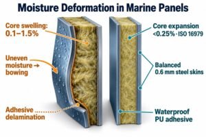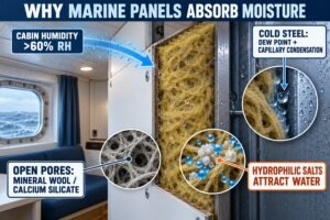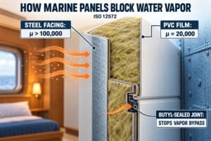
Cabin moisture ruins expensive marine wall panels and ceiling systems before a vessel even finishes sea trials. Delaminated PVC film and rusted steel sheets destroy your project margins fast.
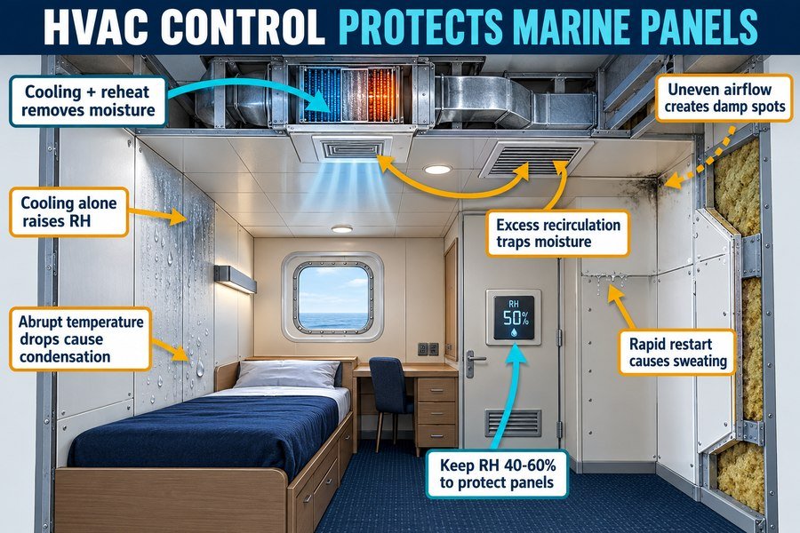
Shipboard HVAC operation shapes humidity around marine interior panels through six core operational factors: central cooling-and-reheat moisture control, sensible-only cooling without dehumidification, abrupt cabin temperature drops, uneven air diffuser distribution, excessive cabin air recirculation, and rapid post-idle system startup. Keeping relative humidity between 40% and 60% prevents panel degradation.
I started my career on the shop floor of a marine outfitting factory, and I now work as a marine outfitting specialist at Magellan Marine. Many ship interior contractors call me when they see water droplets, rust stains, or peeling PVC films on new B-15 cabin bulkheads. They often blame the panel adhesive or the steel mill first. However, my field inspections show that the real culprit is usually how the shipboard HVAC system handles moisture inside the accommodation block. When you source marine wall panels, ceiling panels, and fire doors from factories in Asia for European or American shipyard projects, you need to understand how onboard air conditioning interacts with your materials. Read on to learn how HVAC operation affects cabin humidity so you can specify the right panel coatings and avoid expensive warranty claims.
How Does Ship HVAC Control Regulate Moisture on Marine Accommodation Panels?
High sea humidity attacks cabin bulkheads every single day. Without strict moisture control, wet air seeps into mineral wool cores, corrodes galvanized steel skins, and ruins your handover schedule.
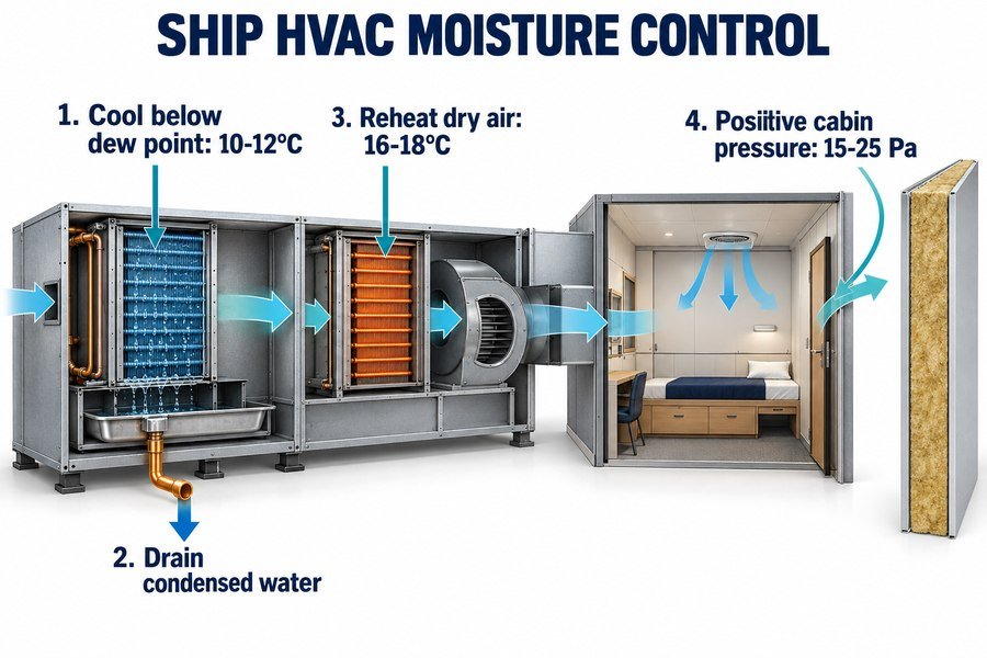
Ship HVAC control regulates moisture on marine accommodation panels through four sequential processes: cooling outside supply air below its dew point (10°C to 12°C), draining condensed water at the central air handling unit, reheating dry air to 16°C to 18°C, and maintaining positive cabin air pressure (15 to 25 Pa).
Sub-Dew-Point Cooling and Condensate Drainage at the Central Air Handling Unit
Marine HVAC systems cannot simply blow cooled sea air straight into crew cabins. According to ISO 7547 and ASHRAE Standard 26 for shipboard air conditioning, outside design air in tropical zones often sits at 35°C with 70% relative humidity1. That outside air holds about 25 grams of water vapor per kilogram of dry air2. To protect marine accommodation panels, the central air handling unit (AHU) first pulls this wet outside air across a chilled water coil or direct expansion coil. The coil cools the air below its dew point to a temperature between 10°C and 12°C. At this cold temperature, the air cannot hold its extra moisture. About 15 to 17 grams of water per kilogram of air condenses into liquid water on the coil fins.
Next, the central AHU collects this liquid water in a sloped stainless steel drain pan and discharges it overboard through trap drains. Last year, I helped a client who was outfitting a offshore support vessel in Southeast Asia. His installation team noticed wet rockwool edges along the bottom tracks of their B-15 wall panels. When I inspected the central AHU room, I saw that the condensate drain traps were clogged with construction dust. Water was overflowing the pan and getting sucked straight into the main supply ducts. Once the shipyard cleaned the drain lines and set the coil temperature to 11°C, the cabin air dried out within six hours.
Supply Air Reheating and Positive Cabin Pressure Control for Marine Wall Panels
After the cooling coil strips the water out of the air, the air is dry, but it is far too cold to blow directly onto marine ceiling panels. If 11°C air hits a steel ceiling panel, the panel surface gets cold and sweats inside the plenum. Because of this risk, the HVAC system runs the third process, which is supply air reheating. A hot water coil or electric reheat element warms the dry supply air up to a safe delivery temperature of 16°C to 18°C. When this air enters the cabin and warms up to the ISO 7547 design indoor temperature of 22°C to 24°C, its relative humidity stabilizes between 45% and 55%3.
The fourth process is maintaining positive cabin air pressure. The supply fans push slightly more air into the accommodation spaces than the exhaust fans remove. This balance creates a positive pressure of 15 to 25 Pascals (Pa) inside the cabins compared to the outside deck. Positive pressure stops unconditioned, salty sea air from sneaking through exterior A-60 watertight doors or corridor gaps and condensing on your interior panels.
| HVAC Moisture Control Process | Target Engineering Value | Authoritative Standard | Direct Impact on Marine Accommodation Panels |
|---|---|---|---|
| 1. Sub-Dew-Point Cooling | 10°C to 12°C coil leaving air temperature | ISO 7547 / ASHRAE Standard 26 | Condenses 15 to 17 g/kg of water vapor before air reaches cabin panels |
| 2. Central Condensate Drainage | 3° to 5° pan slope with 50 mm water seal trap | ASHRAE Shipboard HVAC Guide | Prevents liquid water carryover into supply ducts and ceiling plenums |
| 3. Supply Air Reheating | 16°C to 18°C supply duct delivery temperature | ISO 7547 Section 6 | Keeps diffuser air warm enough to prevent cold-spot sweating on ceiling steel |
| 4. Positive Cabin Pressurization | +15 Pa to +25 Pa relative to weather deck | SOLAS II-2 / DNV Rules | Blocks humid outside marine air from infiltrating panel joints and fire doors |
Why Does Cooling Cabins Without Dehumidification Raise Humidity on Marine Interior Panels?
Crew members love turning down cabin thermostats in tropical waters. If the chiller only lowers air temperature without removing water vapor, your cabin walls quickly turn into wet sponges.
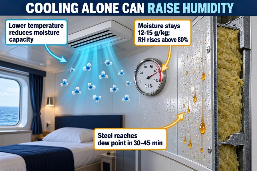
Cooling cabins without dehumidification raises humidity on marine interior panels for three thermodynamic reasons: lower air temperatures reduce the air's moisture-holding capacity, constant absolute humidity (12 to 15 g/kg) drives relative humidity above 80%, and cooled PVC-coated steel skins reach the local dew point within 30 to 45 minutes.
Reduced Air Moisture Capacity and Rising Relative Humidity Under Constant Absolute Moisture
Many procurement officers and project managers assume that colder air is always drier air. When I worked at the panel factory, I used to think the same thing until an HVAC engineer showed me a standard ASHRAE psychrometric chart. Air acts like a sponge, and its ability to hold water depends entirely on its temperature. At 27°C, one kilogram of dry air can hold up to 22.8 grams of water vapor at 100% saturation. When you cool that same kilogram of air down to 18°C, it can only hold 13.0 grams of water vapor.
If a ship uses local fan coil units (FCUs) with chilled water running at 14°C instead of 7°C, the unit performs sensible-only cooling4. It lowers the dry-bulb temperature of the cabin, but it never gets cold enough to condense water out of the air. Because no water leaves the room, the absolute humidity stays locked at 12 to 15 grams of moisture per kilogram of air. As the cabin temperature drops from 26°C down to 19°C while holding 13 grams of moisture, the relative humidity jumps from 60% to over 90%. Every 1°C drop in air temperature without dehumidification increases cabin relative humidity by roughly 4% to 5%.
Dew Point Contact on PVC-Coated Galvanized Steel Marine Interior Panels
When cabin relative humidity climbs above 80%, your marine interior panels face immediate physical danger. Standard B-15 marine wall panels and B-0 ceiling panels use 0.5 mm to 0.7 mm galvanized steel sheets covered with a 0.15 mm decorative PVC film. Steel has a high thermal conductivity of 50 W/(m·K).5 When sensible cooling lowers the cabin air temperature, the thin steel skins of the wall and ceiling panels cool down fast.
Within 30 to 45 minutes of sensible-only cooling, the PVC-coated steel surface temperature drops to match the local dew point temperature, which sits around 17°C to 19°C in a humid cabin. Water vapor in the room instantly condenses into microscopic droplets across the decorative PVC surface and inside the tongue-and-groove joints. Two years ago, I visited a cruise ship refurbishment project where the contractor installed local split-system coolers during port outfitting. They cooled the cabins to 18°C without running the central dehumidifier. Within two weeks, moisture wicked into the unprotected shear edges of 120 wall panels, causing white zinc rust under the PVC film. Turning up the chilled water valve to fail-safe dehumidification mode solved the issue, but replacing those damaged panels cost the contractor $18,000 in material and labor.
| Cooling Operating Mode | Chilled Water Supply Temp | Absolute Cabin Moisture | Resulting Cabin Relative Humidity | Effect on 0.6 mm Galvanized Steel Panels (ISO 7547 Reference) |
|---|---|---|---|---|
| Sensible-Only Cooling (Faulty) | 13°C to 15°C | Remains high at 12 to 15 g/kg | 80% to 95% RH | Panel skin hits dew point in 30 to 45 minutes; water beads on PVC film and rusts cut edges |
| Dehumidified Cooling (Standard) | 6°C to 7°C | Reduced to 7 to 9 g/kg | 45% to 55% RH | Panel skin stays 5°C to 7°C above dew point; rockwool core and steel joints remain completely dry |
| Over-Cooled Sensible Mode | 12°C with high fan speed | 14 g/kg (trapped moisture) | Over 95% RH (Saturation) | Water runs down wall panels into floor C-channels, rotting mineral wool insulation within 48 hours |
How Do Abrupt Cabin Temperature Changes Trigger Condensation on Marine Interior Panels?
Rapid thermostat drops in humid ports shock your cabin interiors. Cold air hits warm steel bulkheads, and water beads form across ceiling joints before anyone notices the damage.
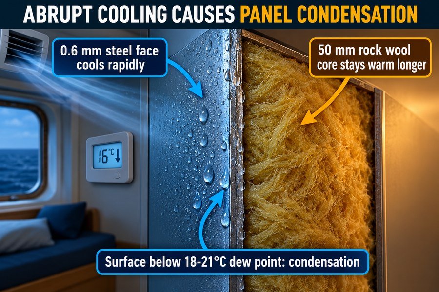
Abrupt cabin temperature changes trigger condensation on marine interior panels through three thermal mechanisms: rapid cooling of the 0.6 mm galvanized steel face sheet, thermal lag inside the 50 mm rockwool insulation core, and a surface temperature drop below the cabin air dew point (typically 18°C to 21°C).
Rapid Cooling of Galvanized Steel Face Sheets Versus Thermal Lag in Rockwool Cores
A marine composite wall panel is made of two very different materials glued together with polyurethane or epoxy adhesive. The outer layers are 0.6 mm galvanized steel sheets, and the inner core is high-density mineral wool (rockwool) with a density of 140 kg/m³ to 160 kg/m³ to meet IMO MSC.307(88) FTP Code fire ratings6. These two materials react to sudden temperature shifts at completely different speeds.
Steel has a high thermal conductivity of 50 W/(m·K)7 and very low thermal mass because it is only 0.6 mm thick. In contrast, the 25 mm or 50 mm rockwool core has a very low thermal conductivity of 0.035 to 0.040 W/(m·K)8. When an officer enters a warm cabin at 28°C and drops the HVAC setpoint straight down to 18°C, cold supply air floods the room. The exposed 0.6 mm steel face sheet loses heat almost immediately, cooling down at a rate of 0.4°C to 0.6°C per minute. Meanwhile, the thick 50 mm rockwool core and the air cavity behind the panel experience thermal lag. They stay warm at 26°C to 28°C for up to two hours. This creates a sharp temperature gradient right across the glue line between the cold steel sheet and the warm insulation core.
Surface Dew Point Drops on Marine Wall Panels and B-15 Fire Doors
Because the steel face sheet cools down much faster than the cabin air can be dehumidified, the panel surface temperature drops below the room's dew point temperature, which typically sits between 18°C and 21°C in humid maritime climates9. Before the HVAC return duct can cycle the room air out to remove water vapor, the cold steel sheet acts like a cold soda can taken out of a refrigerator.
Water condenses on both sides of the cabin side steel skin. On the room side, you see fogging on low-gloss PVC films. On the back side facing the warm rockwool core, warm moisture vapor trapped inside the porous rockwool migrates toward the cold steel skin and condenses right on the polyurethane glue layer. According to Lloyd's Register and DNV interior outfitting guidelines, cyclic wetting of panel adhesives can reduce peel strength by 30% to 50% over 12 months10. I always tell my clients to order wall panels with at least a 60 g/m² to 80 g/m² zinc coating on both the front and back steel surfaces, plus a 5-micron epoxy back-coat. That extra back-coat costs only $0.80 more per square meter in Chinese factories, but it prevents internal adhesive delamination when crew members shock the cabin thermostat.
| Panel Component Layer | Material Specification (IMO FTP Code) | Thermal Conductivity | Temperature After 15-Min Abrupt Cooling (28°C to 18°C Setpoint) | Condensation Risk Level |
|---|---|---|---|---|
| Cabin-Side Steel Skin | 0.6 mm galvanized steel + 0.15 mm PVC film | 50.0 W/(m·K) | Drops rapidly to 17.5°C | High risk; drops below 18°C–21°C dew point and forms surface sweat |
| Adhesive Bond Line | Two-component polyurethane glue (80–120 g/m²) | 0.20 W/(m·K) | Sits at 18.0°C transition zone | Severe risk; interstitial vapor condenses at glue boundary and weakens bond |
| Rockwool Insulation Core | 50 mm mineral wool (150 kg/m³ density) | 0.038 W/(m·K) | Lags behind at 26.5°C | Moderate risk; holds warm humid air pockets that migrate toward cold steel |
| Bulkhead-Side Back Sheet | 0.5 mm galvanized steel with epoxy back-coat | 50.0 W/(m·K) | Remains warm at 27.0°C | Low risk during cabin cooling, but high risk if hull steel is cold |
Why Does Uneven HVAC Airflow Create Humidity Hotspots on Marine Interior Panels?
Poorly balanced ceiling diffusers blast freezing air onto one bulkhead while leaving cabin corners stagnant. Soon, black mold and blistering PVC film ruin specific panels across the deck.
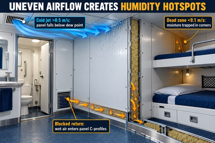
Uneven HVAC airflow creates humidity hotspots on marine interior panels via three aerodynamic faults: high-velocity cold air impingement (over 0.5 m/s) cooling ceiling panels below the dew point, stagnant dead zones (under 0.1 m/s) trapping moisture in corners, and blocked return vents forcing wet air into panel C-profiles.
Cold Air Impingement on Marine Ceiling Panels and Stagnant Corner Dead Zones
ISO 7547 specifies that air velocity in the occupied zone of a ship cabin should stay between 0.15 m/s and 0.35 m/s, and never exceed 0.5 m/s. However, when shipyard HVAC technicians skip proper air balancing during commissioning, airflow inside the cabin becomes uneven. The first aerodynamic fault is high-velocity cold air impingement11. If a ceiling swirl diffuser has broken vanes or an over-opened damper, it throws a concentrated jet of 15°C supply air sideways across the marine ceiling panels or straight down onto an adjacent B-15 wall panel at velocities over 0.5 m/s. This cold jet chills that specific 1-square-meter patch of steel panel down to 16°C. Whenever a crew member opens the cabin door or steps out of the shower, warm cabin air hits that cold 16°C panel patch and condenses immediately.
At the exact same time, bad diffuser placement creates the second aerodynamic fault: stagnant dead zones. Behind bunk beds, wardrobes, or corner bulkheads, air velocity drops below 0.1 m/s. Because dry supply air never sweeps through these corners, local relative humidity climbs 15% to 20% higher than the center of the room12. I inspected a bulk carrier in Nantong where every single cabin had peeling corner profiles behind the crew desks. My anemometer showed 0.8 m/s airflow right under the ceiling diffuser and 0.02 m/s in the desk corner. Adjusting the diffuser dampers took 10 minutes per cabin and stopped the corner mold completely.
Blocked Return Air Vents and Moisture Infiltration into Floor C-Profiles
The third aerodynamic fault happens at the exhaust path. In a standard marine cabin, dry air enters from the ceiling diffuser, picks up moisture from the room, and exits through a door transfer grille or a sanitary exhaust fan in the wet unit. According to ASHRAE Standard 26, the bathroom exhaust fan must pull 50 to 85 m³/h of air continuously to keep moisture moving out of the living space.
Sometimes, interior installation teams accidentally block the lower transfer grille on a marine fire door, or crew members tape over the noisy bathroom exhaust vent. When the return path is blocked, the supply fan over-pressurizes the cabin above 40 Pa. That trapped, moisture-laden air has nowhere to go, so pressure forces it through the 1 mm expansion gaps between marine wall panels and down into the galvanized steel floor C-profiles13. Once wet air enters the cold floor channel resting on the steel deck, it condenses into standing water. Within three to six months, the bottom 50 mm of the wall panel rusts through.
| Airflow Fault Category | Measured Air Velocity / Pressure | Affected Outfitting Zone | Physical Damage to Marine Interior Panels | Corrective Commissioning Action |
|---|---|---|---|---|
| 1. High-Velocity Cold Impingement | Greater than 0.5 m/s at panel surface | Ceiling panels around diffuser and upper wall panels | Localized sub-dew-point cooling, water streaking, and PVC film blistering | Adjust diffuser throw blades to 15°–30° horizontal Coanda spread |
| 2. Stagnant Corner Dead Zones | Less than 0.1 m/s air movement | 90-degree corner profiles and bulkheads behind bunks | Relative humidity exceeds 75% RH; black mildew grows in silicone joints | Relocate supply diffuser or trim cabin furniture clearance to 50 mm |
| 3. Blocked Return / Exhaust Path | Cabin pressure exceeds +40 Pa | Bottom floor C-channels and B-15 fire door frames | Pressurized wet air forces into panel joints, causing bottom-edge steel rust | Keep 150 cm² to 200 cm² clear free area on fire door ventilation grilles |
How Does High Cabin Air Recirculation Increase Moisture on Marine Accommodation Panels?
Ship operators often cut fresh air intake to save chiller fuel. However, trapping used air inside crew cabins builds up heavy moisture that rots your interior panels from within.
High cabin air recirculation increases moisture on marine accommodation panels through three cumulative sources: unvented human respiration and sweat (50 to 100 g/h per person), wet bathroom exhaust leakage (up to 400 g/h per shower), and insufficient dry fresh air makeup (dropping below the ISO 7547 minimum of 40%).
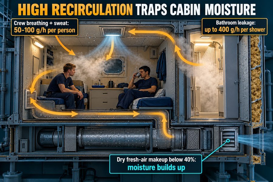
Crew Latent Heat Loads and Wet Sanitary Module Exhaust Leakage in Ship Cabins
A ship cabin is a very small, tightly sealed steel box. Standard crew cabins have an internal volume of only 15 m³ to 25 m³.14 Because the space is so small, internal moisture sources build up much faster than they do in a hotel room on land. The first cumulative moisture source is the crew members themselves. According to ISO 7547 and ASHRAE metabolic tables, a resting adult releases 50 grams of water vapor per hour through breathing and skin perspiration, and an active worker releases up to 100 grams per hour. In a two-person crew cabin over an eight-hour sleep shift, the occupants pump 800 to 1,200 grams of pure water vapor into the cabin air.
The second source is wet bathroom exhaust leakage from the prefabricated sanitary unit. A single 10-minute hot shower releases 300 to 400 grams of steam.15 In a properly balanced system, all sanitary air is exhausted 100% overboard and is never recirculated. However, when recirculation fans pull too hard on the cabin return plenum, negative pressure draws steam out around the bathroom B-0 door seals into the main cabin before the bathroom fan can capture it. That steam settles directly onto the surrounding marine accommodation panels and ceiling hatches.
Insufficient Fresh Air Makeup Ratios Under ISO 7547 and Panel Edge Corrosion
The third moisture source is an insufficient fresh air makeup ratio. Under ISO 7547 Section 7, a marine HVAC system must supply at least 0.008 m³/s (28.8 m³/h) of fresh conditioned outdoor air per person, and the fresh air ratio must be at least 40% of the total supply air volume.16 This means the maximum allowable cabin air recirculation rate is 60%.
In practice, some ship engineers close the fresh air intake dampers down to 15% or 20% (an 80% to 85% recirculation ratio) when sailing through hot tropical waters to reduce the cooling load on the main chiller. If the local recirculation pathway bypasses the primary sub-dew-point dehumidification coil, all the moisture from crew breathing and shower leakage recirculates in a closed loop. Within four hours, cabin relative humidity climbs from 50% to over 75%. When I supply marine wall panels and ceiling panels from China to European shipyards, I always remind buyers that high recirculation also concentrates human sweat acids and cleaning chemicals in the air. If you use standard 40 g/m² galvanized steel in high-recirculation cabins, the raw top and bottom cut edges of the panels will corrode within one year.17 You must specify at least Z120 (120 g/m² zinc coating) or aluminized zinc steel for those projects.
| Air Recirculation Ratio | Fresh Air Makeup % (ISO 7547 Min: 40%) | Total Cabin Latent Moisture Load (2 Crew + 1 Shower) | Resulting Cabin Relative Humidity | Impact on Marine Accommodation Panels and Fire Doors |
|---|---|---|---|---|
| 50% Recirculation (Optimal) | 50% conditioned fresh air | 500 g/h safely diluted and exhausted | 45% to 50% RH | Zero moisture accumulation; panel joints and rockwool stay dry for 20+ years |
| 60% Recirculation (ISO Limit) | 40% conditioned fresh air | 500 g/h balanced at threshold | 55% to 60% RH | Safe operating limit under ISO 7547; requires intact PVC film and sealed edges |
| 85% Recirculation (Excessive) | Only 15% fresh air makeup | 500 g/h trapped in closed cabin loop | 75% to 88% RH | Moisture saturates mineral wool through panel seams and corrodes steel door frames |
What Condensation Occurs on Marine Interior Panels During Post-Idle HVAC Startup?
Shutting down ship HVAC during shipyard outfitting or port layups lets tropical humidity soak every cabin. Turning the chillers back on at full blast triggers an indoor rainstorm.
During post-idle HVAC startup, three types of condensation occur on marine interior panels: surface film sweating on exposed PVC-coated steel sheets, interstitial condensation inside saturated rockwool insulation cores, and concealed dripping inside ceiling plenums and fire door frames. Gradual pull-down at 1°C to 2°C per hour prevents damage.
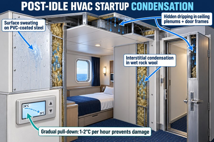
Surface Film Sweating and Interstitial Rockwool Condensation During Rapid Chiller Pull-Down
The most dangerous moment for marine interior outfitting materials happens during shipyard commissioning or after a vessel sits idle in a warm port. When the HVAC system is turned off for several days in a shipyard in China, Vietnam, or Indonesia, ambient air at 32°C and 80% relative humidity fills every cabin, corridor, and ceiling void. Because marine wall panels and ceiling panels are not hermetically sealed at their top and bottom edges, this humid air slowly diffuses into the porous 150 kg/m³ rockwool cores18 until the entire cabin structure is at moisture equilibrium with the tropical air.
When the commissioning team suddenly starts the chillers at 100% capacity to pull the cabin down from 32°C to 20°C in one hour, two types of condensation strike at once. The first type is surface film sweating. As 14°C supply air hits the 32°C PVC-coated wall panels, the boundary layer of air drops below its 28°C dew point19, coating every wall in a visible sheet of water. The second type is interstitial condensation. The 0.6 mm steel skins cool down to 20°C rapidly, trapping 32°C wet air inside the rockwool core. Water vapor condenses inside the rockwool fibers at a rate of 80 to 150 grams per square meter of panel area20. Wet rockwool loses its compressive strength, sags inside the panel21, and creates hollow blisters on the steel face.
Concealed Plenum Dripping on Marine Ceilings and Step-by-Step HVAC Pull-Down Protocols
The third type of condensation during post-idle startup is concealed dripping inside ceiling plenums and hollow B-15 fire door frames. Above your B-0 or B-15 marine ceiling panels sits a 300 mm to 500 mm void space containing uninsulated brackets, cable trays, and steel deckhead stiffeners22. During an abrupt HVAC startup, cold supply ducts chill the stagnant, humid air trapped inside the ceiling void, and cold cabin air chills the underside of the steel ceiling planks. Water droplets form on the top side of the ceiling panels, soak through the 25 mm mineral wool pads laid on top of the ceiling, and drip through the recessed LED light cutouts and inspection hatches. Similarly, moisture condenses inside hollow 1.5 mm steel fire door frames, pooling at the bottom sill and rusting the hinge reinforcements from the inside out23.
I learned this lesson the hard way three years ago when a European client called me in a panic two days before vessel delivery. Their shipyard crew had turned on the main chillers at full power after a two-week barge tow in July. Water was dripping from over 300 ceiling panels. To prevent this disaster on your projects, you must instruct the shipyard to follow a strict gradual HVAC pull-down protocol. First, run the central dehumidification coil with the reheat coils turned up so supply air enters at 26°C to 28°C for the first 12 hours24, stripping moisture until cabin relative humidity drops below 55%. Only after the air is dry should the operators lower the cabin temperature at a controlled rate of 1°C to 2°C per hour until reaching 22°C.
| Post-Idle Condensation Type | Exact Location on Outfitting System | Moisture Volume Accumulated | Structural & Visual Damage to Products | Mandatory Prevention Protocol |
|---|---|---|---|---|
| 1. Surface Film Sweating | Exposed cabin-side PVC film on wall panels and fire doors | 30 to 60 g/m² on exposed panel faces | Water streaks, staining around aluminum H-profiles, and silicone mold | Run dehumidification-only mode for 12 hours until cabin RH drops below 55% before cooling |
| 2. Interstitial Core Condensation | Inside 50 mm rockwool core and polyurethane glue line | 80 to 150 g/m² trapped inside insulation | Polyurethane glue hydrolysis, panel face blistering, and wet sagging insulation | Limit cabin temperature pull-down rate to 1°C to 2°C per hour maximum |
| 3. Concealed Plenum & Frame Dripping | Top side of B-15 ceiling panels and inside hollow 1.5 mm door frames | 100 to 250 g/m² pooling in ceiling pans | Rust bleed at ceiling joints, ruined mineral wool pads, and rusted door hinges | Open ceiling inspection hatches during dehumidification purge and specify epoxy primer inside door frames |
Conclusion
Proper shipboard HVAC control prevents condensation and protects your marine wall panels, ceilings, and fire doors. Pair balanced cabin humidity with certified galvanized materials to guarantee long-lasting ship interiors.
-
"Correlating indoor and outdoor temperature and humidity ...", https://pubmed.ncbi.nlm.nih.gov/34138487/. ISO 7547 or an equivalent shipboard HVAC design standard can document the tropical outside-air design condition used for accommodation air-conditioning calculations. Evidence role: expert_consensus; source type: institution. Supports: Shipboard accommodation HVAC design commonly uses an outside tropical design condition of about 35°C and 70% relative humidity.. Scope note: The standard supports the design basis, not the actual weather conditions for every tropical voyage or port. ↩
-
"The University of Maine", https://umaine.edu/. A psychrometric chart or university HVAC reference can verify that air at 35°C and 70% relative humidity has a humidity ratio of roughly 0.025 kg water per kg dry air. Evidence role: mechanism; source type: education. Supports: Air at 35°C and 70% relative humidity contains approximately 25 grams of water vapor per kilogram of dry air.. Scope note: The exact value varies slightly with barometric pressure and rounding assumptions. ↩
-
"Residential indoor temperatures and health: A scoping review ...", https://pmc.ncbi.nlm.nih.gov/articles/PMC13090820/. Psychrometric references can show that air dehumidified near 10°C to 12°C and then reheated to typical accommodation temperatures has a relative humidity in the approximate mid-range stated. Evidence role: mechanism; source type: education. Supports: After dehumidification and reheating, supply air entering a 22°C to 24°C cabin can produce an indoor relative humidity around 45% to 55%.. Scope note: The final relative humidity depends on actual supply-air humidity ratio, room sensible and latent loads, ventilation rate, and occupant moisture generation. ↩
-
"Dehumidification at Part Load", https://publications.energyresearch.ucf.edu/wp-content/uploads/2018/06/FSEC-GP-151-06.pdf. HVAC references describe dehumidification as latent cooling that occurs when a cooling coil surface is below the entering air dew point; a higher chilled-water temperature can therefore produce mainly sensible cooling when the coil remains above dew point. Evidence role: mechanism; source type: education. Supports: A fan coil supplied with relatively warm chilled water may cool air sensibly without removing moisture if the coil surface does not fall below the dew point.. Scope note: The source would support the physical mechanism, while the exact 14°C versus 7°C outcome depends on coil design, airflow, entering-air conditions, and control settings. ↩
-
"Material Properties: 304 Stainless (UNS S30400)", https://trc.nist.gov/cryogenics/materials/304Stainless/304Stainless_rev.htm. Engineering material-property references list the thermal conductivity of carbon steel at room temperature at about 45–60 W/(m·K), which is consistent with the article’s representative value of 50 W/(m·K). Evidence role: statistic; source type: education. Supports: Steel has a thermal conductivity on the order of 50 W/(m·K).. Scope note: Thermal conductivity varies by steel alloy, temperature, and coating layers; the value is representative rather than specific to every galvanized panel skin. ↩
-
"What Is the Purpose and Scope of the IMO FTP Code?", https://magellanmarinetech.com/what-purpose-scope-of-imo-ftp-code/. The IMO 2010 FTP Code, adopted by MSC.307(88), establishes test procedures used to classify the fire performance of marine materials and constructions, including bulkhead and lining assemblies. Evidence role: definition; source type: institution. Supports: Marine composite wall panels using mineral wool cores may be specified to meet IMO MSC.307(88) FTP Code fire-performance requirements.. Scope note: The Code supports the regulatory framework for testing and classification, but it does not by itself verify that this specific panel construction or rockwool density meets a given rating. ↩
-
"Thermal Conductivity", http://hyperphysics.phy-astr.gsu.edu/hbase/Tables/thrcn.html. Engineering reference tables commonly list carbon steel thermal conductivity on the order of 45–60 W/(m·K) near room temperature, supporting the use of approximately 50 W/(m·K) as a representative value. Evidence role: statistic; source type: education. Supports: Steel has a thermal conductivity around 50 W/(m·K), much higher than mineral wool insulation.. Scope note: Thermal conductivity varies with steel grade, coating, temperature, and measurement method; the cited value is representative rather than specific to the exact galvanized sheet used here. ↩
-
"Determination of Thermal Properties of Mineral Wool ... - PMC", https://pmc.ncbi.nlm.nih.gov/articles/PMC10488771/. Reference data for mineral wool insulation report thermal conductivity values typically in the range of about 0.03–0.04 W/(m·K), supporting the stated low-conductivity range for rockwool-type insulation. Evidence role: statistic; source type: research. Supports: A rockwool or mineral-wool core can have thermal conductivity around 0.035–0.040 W/(m·K).. Scope note: Published values depend on density, binder, temperature, moisture content, and test standard; the source would support a typical range rather than this exact product formulation. ↩
-
"Heat Index", https://www.weather.gov/arx/heat_index. Psychrometric relations show that warm indoor air at high relative humidity can have dew-point temperatures around 18–21°C, supporting the condensation threshold described for humid cabin conditions. Evidence role: mechanism; source type: government. Supports: In humid maritime indoor conditions, the dew point can fall in the 18–21°C range, making condensation possible when metal surfaces cool below that temperature.. Scope note: The dew-point range depends on actual air temperature and relative humidity; climatological or psychrometric data would support plausibility, not prove that all maritime cabins have this dew point. ↩
-
"What Are Aluminum Honeycomb Panels?", https://magellanmarinetech.com/what-are-aluminum-honeycomb-panels/. Studies of polyurethane and epoxy adhesive joints report that moisture exposure and wet–dry or hygrothermal cycling can reduce bond strength, including peel or lap-shear performance, supporting the general degradation mechanism. Evidence role: expert_consensus; source type: paper. Supports: Repeated moisture exposure can materially reduce the strength of polyurethane or epoxy adhesive bonds in panel assemblies.. Scope note: The specific 30–50% loss over 12 months and attribution to Lloyd's Register or DNV would require a directly matching guideline or test report; broader adhesive-aging studies only provide contextual support. ↩
-
"Comparison of Two-Phase Electronic Cooling Using Free Jets ...", https://engineering.purdue.edu/mudawar/files/articles-all/1995/1995_8.pdf. HVAC and building-physics literature describes air jets from diffusers as producing localized high-velocity regions and surface cooling where cold supply air impinges on nearby surfaces; this supports the mechanism but not the article’s specific ship-cabin measurements. Evidence role: mechanism; source type: paper. Supports: A misadjusted or damaged diffuser can create a concentrated cold air jet that impinges on nearby panels and cools local surfaces.. Scope note: Most available studies address buildings or generic HVAC jets rather than marine ceiling panels specifically. ↩
-
"The dichotomy of relative humidity on indoor air quality", https://pubmed.ncbi.nlm.nih.gov/17499853/. Indoor-air and ventilation studies report that low air movement and poor mixing can create spatial humidity gradients and localized high relative humidity; this supports the general relationship but may not establish the article’s exact 15–20 percentage-point increase. Evidence role: general_support; source type: paper. Supports: Stagnant corners with very low air movement can have higher local relative humidity than the well-mixed center of a room.. Scope note: The cited literature may document humidity stratification or gradients without matching the exact numerical range in ship cabins. ↩
-
"Building Science Introduction - Moisture Flow", https://basc.pnnl.gov/information/building-science-introduction-moisture-flow. Building-envelope and moisture-transport literature explains that air-pressure differences can drive moist air through small cracks and joints, where condensation may occur on colder surfaces; this supports the pressure-driven moisture pathway but not the exact 1 mm gap geometry or corrosion timeline stated for this cabin assembly. Evidence role: mechanism; source type: research. Supports: A blocked return or exhaust path can create pressure-driven leakage of moist cabin air through panel joints, allowing condensation in colder cavities.. Scope note: Evidence is likely to be contextual from building science or HVAC pressure studies rather than direct testing of marine floor C-profiles. ↩
-
"How Does Accommodation Panel Thickness Fit Ship Interior ...", https://magellanmarinetech.com/how-accommodation-panel-thickness-fit-ship-interior-constraints/. A ship accommodation standard or maritime design reference should be cited to document the typical dimensional range of crew cabins and to show that small cabin volumes are common in merchant-vessel accommodation design. Evidence role: general_support; source type: institution. Supports: Standard crew cabins typically have internal volumes in the range of 15 m³ to 25 m³.. Scope note: Such sources may specify cabin floor area or minimum headroom rather than directly stating total cabin volume, so the cited support may require a transparent volume calculation. ↩
-
"Moisture control and ventilation - NCBI - NIH", https://www.ncbi.nlm.nih.gov/books/NBK143947/. A building-science or indoor-air-quality source should be cited to document measured or estimated moisture generation from showering and to place the 300–400 g per 10 minutes figure in context. Evidence role: statistic; source type: research. Supports: A hot shower can add several hundred grams of water vapor to indoor air over a short period.. Scope note: Moisture release varies with water temperature, flow rate, enclosure geometry, exhaust flow, and duration, so the cited value is best treated as an approximate range rather than a universal constant. ↩
-
"requirements for ventilation of different rooms on the ships", https://www.academia.edu/97496025/Main_requirements_for_ventilation_of_different_rooms_on_the_ships. ISO 7547 or an authoritative maritime HVAC reference citing it should be used to verify the minimum outdoor-air supply rate per person and the minimum fresh-air proportion for accommodation spaces. Evidence role: definition; source type: institution. Supports: ISO 7547 specifies minimum fresh-air supply requirements for ship accommodation HVAC systems, including a per-person outdoor-air rate and a minimum outside-air fraction.. Scope note: Because ISO standards are often paywalled, an accessible secondary source may quote the requirement but should be checked against the current edition of the standard. ↩
-
"Effects of Ambient Temperature and State of Galvanized Layer ...", https://pmc.ncbi.nlm.nih.gov/articles/PMC10220731/. A corrosion-engineering or coated-steel reference should be cited to support the mechanism that high humidity, chloride-contaminated or chemically contaminated indoor air, and exposed cut edges accelerate zinc-coated steel corrosion, especially where coating mass is low. Evidence role: mechanism; source type: paper. Supports: Low-coating-mass galvanized steel with exposed cut edges is vulnerable to accelerated corrosion in humid, chemically contaminated marine accommodation environments.. Scope note: A general corrosion source can support the mechanism and relative risk, but the exact “within one year” service-life claim would require field data or accelerated testing under comparable marine accommodation conditions. ↩
-
"Water Vapor Permeability and Thermal Conductivity as a ...", https://web.ornl.gov/sci/buildings/conf-archive/2004%20B9%20papers/077_Valovirta.pdf. Mineral wool literature describes rockwool as a porous, vapor-permeable insulation material, which provides contextual support for the possibility of moisture migration into panel cores under humid conditions. Evidence role: mechanism; source type: paper. Supports: Humid air or water vapor can migrate into porous rockwool insulation cores when panels are not vapor-tight.. Scope note: Such sources establish vapor permeability in general; they do not by themselves quantify diffusion rates for this exact marine panel construction. ↩
-
"CHAPTER 5: Understand the Role of Dew Point", https://www.rit.edu/ipi/sites/rit.edu.ipi/files/documents/5_Sustainable_Preservation_Practices_Understand_Dew_Point.pdf. Psychrometric principles show that condensation occurs when air in contact with a surface is cooled below its dew-point temperature; air at 32°C and 80% relative humidity has a dew point near 28°C. Evidence role: mechanism; source type: education. Supports: Cold supply air and cooled surfaces can bring humid boundary-layer air below its dew point, causing surface sweating.. Scope note: This verifies the condensation mechanism and dew-point relationship, not the exact airflow pattern or boundary-layer temperature in the described cabin. ↩
-
"Hygrothermal analysis of masonry wall with wool glass ...", https://www.academia.edu/78967412/Hygrothermal_analysis_of_masonry_wall_with_wool_glass_interior_insulation. Hygrothermal modeling and mineral-wool moisture studies can support that vapor condensation may occur within fibrous insulation when temperature gradients bring internal regions below the dew point, although the cited source should be checked against the article's specific mass-per-area estimate. Evidence role: mechanism; source type: paper. Supports: Interstitial condensation can occur inside mineral wool under rapid cooling and humid initial conditions, potentially accumulating measurable moisture.. Scope note: The general mechanism is well supported; the exact 80–150 g/m² quantity likely requires either calculation, testing, or a source using comparable panel geometry and boundary conditions. ↩
-
"The Influences of Moisture on the Mechanical, Morphological ...", https://pmc.ncbi.nlm.nih.gov/articles/PMC7288152/. Research on mineral-wool insulation reports that moisture can degrade mechanical or thermal performance and that fibrous insulation may deform or settle when exposed to wetting and loading, giving contextual support to concerns about sagging in panels. Evidence role: general_support; source type: paper. Supports: Moisture exposure can impair rockwool or mineral-wool mechanical performance and contribute to deformation or sagging.. Scope note: Evidence may address mineral wool broadly rather than the exact 150 kg/m³ marine panel core and adhesive assembly described here. ↩
-
"How Does HVAC Load Interact with Marine Accommodation ...", https://magellanmarinetech.com/how-hvac-load-interact-with-marine-accommodation-panel-insulation/. Marine accommodation and HVAC design references describe ceiling voids or plenums as spaces used for services such as ducts, cables, supports, and structural members, supporting the general arrangement described in the article. Evidence role: general_support; source type: institution. Supports: Marine ceiling plenums commonly contain service runs and metal components that may act as condensation surfaces.. Scope note: The source may confirm the existence and function of ceiling voids but may not prescribe the exact 300–500 mm dimension for every vessel type. ↩
-
"GUIDE (Guiding an Improved Dementia Experience) Model", https://www.cms.gov/priorities/innovation/innovation-models/guide. Corrosion and building-physics references support that condensation on or within steel cavities can provide the electrolyte needed for internal corrosion, especially where moisture pools and ventilation is limited. Evidence role: mechanism; source type: government. Supports: Condensation inside hollow steel door frames can pool and promote hidden corrosion of internal reinforcements.. Scope note: This supports the corrosion mechanism for steel cavities generally, not a documented failure rate for hollow marine fire-door frames of 1.5 mm steel. ↩
-
"Supplemental Dehumidification in Warm-Humid Climates", https://www1.eere.energy.gov/buildings/publications/pdfs/building_america/measure_guideline_dehumidification_warmhumid.pdf. HVAC references describe dehumidification with reheat as a method for removing moisture while avoiding excessive space cooling, which supports the logic of a warm dehumidification purge before lowering cabin temperature. Evidence role: mechanism; source type: institution. Supports: Using dehumidification with reheat can reduce indoor humidity before active cooling, lowering condensation risk during startup.. Scope note: The cited source is likely to support the dehumidification-with-reheat principle; the exact 26–28°C setpoint and 12-hour duration require project-specific calculation or commissioning guidance. ↩