Replacing marine panels is hard. If you measure wrong, panels will not fit, causing expensive delays. Here is how to measure wall space correctly for a perfect retrofit.
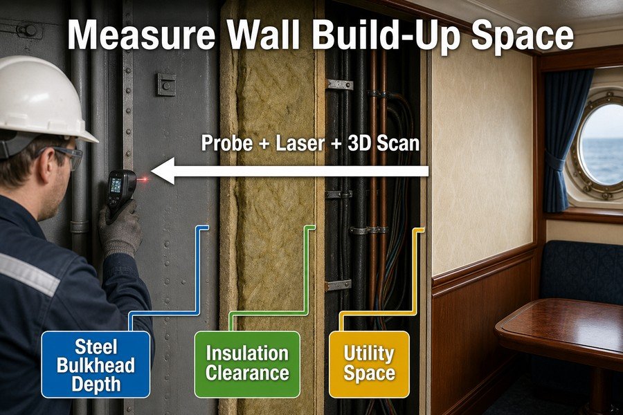
To measure existing wall build-up space for retrofit marine panels, you must check three areas: the steel bulkhead depth, insulation clearance, and utility space. Using physical probing, laser distance meters, and 3D scanning guarantees exact measurements, preventing installation clashes and saving high labor costs in drydock.
It is easy to buy panels from suppliers in China or Vietnam, but making them fit an old ship is very tough. You want to avoid paying extra money to local fitters in Europe or the United States to cut panels on site because your dimensions were wrong. Let us break down the exact ways to measure the space perfectly so your interior outfitting project runs smoothly from start to finish.
What Survey Data Confirms Wall Cavity Depths for Retrofit Marine Wall Panels?
Guessing cavity depths ruins interior projects. If the new panels hit old pipes, you lose time. Proper survey data removes all this risk easily.
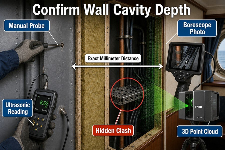
Four types of survey data confirm wall cavity depths: manual drill probe measurements, ultrasonic thickness readings, 3D laser point clouds, and borescope camera photos. Gathering all four types gives you the exact millimeter distance between the steel structure and the panel face without ripping down the wall.
When I worked at the marine outfitting factory, I saw many overseas buyers order standard 50mm thick marine wall panels without checking the real wall cavity depth. When the panels arrived at the shipyard, they did not fit because hidden steel brackets were in the way. You must collect four specific types of survey data to avoid this exact problem.
Manual Drill Probes and Borescope Camera Inspections
The first two types of survey data are manual drill probe measurements and borescope camera photos1. To get this data, workers drill a small 10mm hole into the old panel. They push a thin metal measuring probe inside until it hits the steel bulkhead. This manual probe gives you a direct, hard number in millimeters. I always advise my clients to follow this up with borescope camera photos. A borescope is a small flexible camera that goes through the same drill hole. The photos from the borescope show you exactly what is inside the cavity. The manual probe tells you the depth is 150mm, but the borescope photo shows you that an electrical cable tray takes up 100mm of that space. Now you know you only have 50mm of clear depth left.
Ultrasonic Thickness and 3D Laser Point Clouds
The next two types of data are ultrasonic thickness readings and 3D laser point clouds. Ultrasonic gauges send sound waves through the steel to tell you the exact thickness of the existing steel bulkhead2, usually between 5mm to 8mm on standard commercial vessels3. This helps you understand if the steel itself has rusted and swelled. Finally, 3D laser point clouds give you a full digital map of the entire room4. Instead of just knowing the depth in one spot, the laser point cloud data shows you the cavity depth across the entire 10-meter long wall. By combining manual probes, borescope photos, ultrasonic readings, and 3D point clouds, you get a 100% complete picture of the wall cavity.
| Survey Data Type | Tool Used | Primary Purpose | Accuracy Level |
|---|---|---|---|
| Manual Drill Probe | Metal Depth Gauge | Measures raw distance to steel | +/- 2mm |
| Borescope Photos | Flexible Endoscope | Identifies hidden pipes/cables | Visual Confirmation |
| Ultrasonic Reading | Ultrasonic Thickness Gauge | Measures steel plate thickness | +/- 0.1mm |
| 3D Laser Point Cloud | 3D Laser Scanner (e.g., Faro) | Maps the entire room structure | +/- 1mm |
How to Verify Existing Bulkhead Spacing Before Ordering Replacement Marine Wall Panels?
Ordering panels without checking bulkhead spacing leads to wasted money. You need to know the exact distance before placing an overseas order to avoid issues.
You verify existing bulkhead spacing using three reliable methods: making physical wood templates, using digital laser distance meters, and applying traditional string lines with plumb bobs. Using all three methods ensures your factory dimensions match the actual steel room, accounting for slanted walls or structural changes.
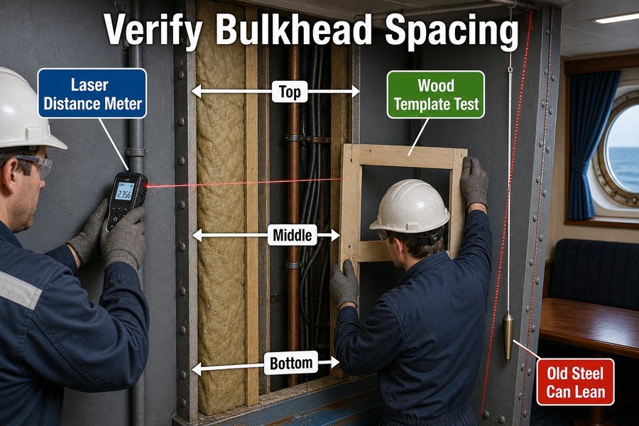
I often see procurement teams rely solely on old ship drawings from 20 years ago5. This is a huge mistake. A ship changes shape over years at sea.6 If you just send the old drawing to a factory in Asia, the new marine wall panels will not match the real space. You must verify the actual bulkhead spacing using three proven methods before you sign the purchase order.
Using Digital Laser Distance Meters for Bulkhead Spacing
The fastest method is using digital laser distance meters. You place the laser meter on one steel bulkhead and shoot the laser to the opposite bulkhead. A good quality laser meter costs about $150 and gives you the exact distance in seconds. However, you cannot just measure once. You must measure the spacing at the bottom near the deck, in the middle, and at the top near the ceiling7. In a typical cabin, the distance might be 2400mm at the floor but 2385mm at the ceiling because the steel has slanted over time. If you only measure the floor, your custom panels will be 15mm too wide at the top.
Physical Wood Templates and String Lines for Alignment
Digital tools are great, but physical checks are safer. The second method is making physical wood templates. You build a cheap wooden frame that matches the exact size of your new panel layout. You physically carry this wood frame into the ship and try to fit it against the bulkhead. If the wood template gets stuck, your panels will get stuck too. The third method is applying traditional string lines with plumb bobs. A plumb bob is a heavy metal weight on a string. You hang it from the top corner of the bulkhead down to the floor. Gravity pulls the string perfectly straight.8 You then measure the distance from the string to the steel wall at different heights. This proves exactly how much the bulkhead leans. Using laser meters, wood templates, and plumb bobs together gives you total confidence in your measurements.
| Verification Method | Tool Required | Best Application | Time Needed per Cabin |
|---|---|---|---|
| Digital Laser | Laser Distance Meter | Fast, basic distance checks | 5 Minutes |
| Wood Template | Plywood and Saws | Testing complex corners | 1 Hour |
| Plumb Bob Line | Weighted String | Checking vertical alignment | 15 Minutes |
Why Use 3D Laser Scanning to Verify Wall Panel Fit in Ship Retrofits?
Older ships do not have straight walls. Steel bends over years at sea. Traditional measuring tools often miss these complex curves, but new technology solves this.
You use 3D laser scanning for marine retrofits for three main reasons: it provides sub-millimeter accuracy, it maps all hidden pipe clashes, and it captures millions of data points quickly. This digital model prevents costly rework and drastically reduces the time ships spend in expensive drydocks.
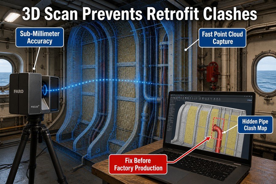
When I was helping a client upgrade a 15-year-old cruise ship last year, the shipyard charged $20,000 per day just for the drydock fee. Every hour counts. If you use standard tape measures, human error will delay the project. 3D laser scanning is now the industry standard for ship retrofits because it removes all guesswork and protects your profit margins.
Achieving Sub-Millimeter Accuracy and Fast Data Capture
The first reason to use 3D scanning is its sub-millimeter accuracy9. A marine fire door or a B-15 wall panel requires a very tight fit to pass safety inspections. A tape measure might bend or sag, giving you a reading that is 5mm off. A high-end 3D scanner, like a Leica or Faro system, shoots millions of light beams per second to measure the room. It gives you a 3D model that is accurate to within 1mm. The second reason is fast data capture. Measuring a large public room on a ship with a tape measure could take three workers a full week. A 3D scanner can capture that same room in just one day10. You pay a scanning company about $1,500 for a day of work, but you save thousands of dollars in labor time.
Mapping Hidden Pipe Clashes in Ship Retrofits
The third and most important reason is mapping all hidden pipe clashes. A ship is packed with air conditioning ducts, water pipes, and thick cable trays. When you import the 3D laser scan into your CAD software, you can place your new digital marine panels directly into the digital ship room. The software will instantly highlight a clash11 if a new wall panel hits an old water pipe. You see the problem on your computer screen a month before the actual panels are manufactured in the factory. This allows you to adjust the panel sizes early. Without this technology, you only discover the clash during installation, forcing you to stop work and modify the panels by hand.
| Scanning Feature | Traditional Measuring | 3D Laser Scanning | Benefit to Buyer |
|---|---|---|---|
| Accuracy | +/- 5mm to 10mm | +/- 1mm | Perfect factory fit |
| Speed | Days or Weeks | Hours | Saves drydock fees |
| Clash Detection | Manual Guesswork | Automatic Digital Alerts | Prevents on-site rework |
| Initial Cost | Low (Basic tools) | Higher ($1500+ per day) | Huge overall project savings |
How to Confirm Available Space Behind Existing Marine Wall Linings?
You cannot tear down all existing walls just to look behind them. You need smart ways to see the hidden space before the shipyard work begins.
To confirm available space behind existing marine wall linings, you must follow three steps: drill 10mm inspection holes, insert flexible borescope cameras to inspect visually, and measure the clear depth to pipes using a depth gauge. This safely maps the hidden void without destroying the current cabin.
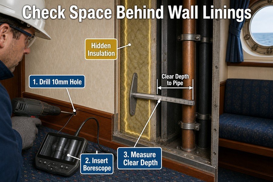
Before you order new marine ceiling panels or wall partitions, you must know how much empty space exists behind the old ones. Standard B-15 marine panels are usually 25mm or 50mm thick.12 If you order 50mm panels, but there is only 30mm of space between the old wall line and a massive steel beam, your new panels will not fit. You need a safe process to confirm this space.
Drilling Inspection Holes and Using Borescope Cameras
The first step is to drill 10mm inspection holes. You do not want to destroy the cabin before the new materials arrive, so you pick hidden spots. I always tell workers to drill near the bottom baseboard or behind where a bed will go. A 10mm hole is easy to patch if the project gets delayed. The second step is to insert flexible borescope cameras into these holes to inspect the space visually13. A good borescope has a bright LED light on the end. When you push it into the dark cavity, you can look at the screen and see exactly what is inside. You might see empty air, or you might see thick A-60 rockwool insulation blocks14. You need this visual proof because ship drawings rarely show exactly how the original workers packed the insulation 15 years ago.
Measuring Clear Depth to Pipes with a Depth Gauge
The final step is to measure the clear depth to pipes using a depth gauge. Once the camera confirms what is inside, you insert a rigid metal depth gauge through the same hole. You push it straight until it touches the first hard obstacle. This might be the main steel hull, or it might be a rigid PVC water pipe. If the gauge goes in 80mm before hitting a pipe, and your new panel needs 50mm of depth plus a 20mm air gap for ventilation15, you know you have exactly 10mm of extra safety space. Following these three steps ensures you order the correct panel thickness from your supplier every single time.
| Inspection Step | Tool Used | Action Taken | Critical Output Data |
|---|---|---|---|
| Step 1 | 10mm Drill Bit | Create access holes safely | Entry point for tools |
| Step 2 | Borescope Camera | Visual inspection of cavity | Identifies insulation/pipes |
| Step 3 | Metal Depth Gauge | Physical distance push | Exact millimeter clearance |
What Tolerances Apply When Fitting Retrofit Wall Panels to Deformed Steel Structures?
Steel bulkheads on ships are never perfectly flat. If you order panels with zero tolerance, they will fail during installation. You must use the right margins.
Three strict tolerances apply when fitting retrofit panels to deformed steel: a +/- 3mm gap for panel joint profiles, a 10mm to 15mm allowance for steel bulkhead deflection per IACS rules, and a 25mm minimum clearance for rockwool packing. Following these ensures compliance and a flat finish.

In the marine industry, steel deforms. Heavy cargo, rough ocean waves, and welding heat cause the steel hull to warp.16 When I worked closely with European shipyards, I learned that you can never design a marine interior with zero tolerance. You must design gaps into your plan, or the decorative wall will look wavy and ugly. There are three strict tolerances you must apply to your order.
Managing Joint Profile Gaps and Steel Bulkhead Deflection
The first tolerance is a +/- 3mm gap for panel joint profiles. When you connect two marine wall panels using a PVC or aluminum H-profile, you cannot push them tightly against each other. The ship vibrates constantly. If panels have zero gap, they will rub together and squeak loudly. Leaving a 3mm tolerance allows the panels to shift slightly during rough seas without making noise. The second tolerance is a 10mm to 15mm allowance for steel bulkhead deflection. According to the International Association of Classification Societies (IACS) standard No. 47, shipyard steel construction has acceptable deformation limits. A large steel wall might safely bow inward by 10mm. If your substructure framing does not have adjustable brackets to absorb this 10mm to 15mm deflection, your new wall panels will follow the bent steel and look totally crooked.
Required Clearances for Rockwool Insulation Packing
The third tolerance is a 25mm minimum clearance for rockwool packing. If you are retrofitting a wall that requires an A-60 fire rating under SOLAS Chapter II-2 regulations17, you cannot just push the decorative panel directly against the bare steel. You must leave space for the fireproof rockwool. Even if the old rockwool is already there, you must ensure there is at least a 25mm gap between the back of the panel and any steel stiffeners to fit additional insulation or air gaps properly. Applying these three tolerances guarantees that your final wall is flat, quiet, and legally compliant with fire safety rules.
| Tolerance Type | Value Required | Governing Standard | Reason for Tolerance |
|---|---|---|---|
| Panel Joint Gap | +/- 3mm | Manufacturer Specs | Prevents vibration squeaking |
| Steel Deflection | 10mm to 15mm | IACS No. 47 | Absorbs bent steel walls |
| Insulation Clearance | 25mm Minimum | SOLAS Chapter II-2 | Allows proper rockwool packing |
Conclusion
Accurate space measurement ensures your retrofit marine panels fit perfectly. Proper surveys, 3D scanning, and strict tolerances prevent delays, saving you money and protecting your project's final quality.
-
"[PDF] Borescope-Aided Inspection May Be Useful in Some Drywood ...", https://ucanr.edu/sites/default/files/2015-07/216853.pdf. A neutral technical source should document that borescopes/endoscopes are used for visual inspection of inaccessible internal spaces through small openings, supporting their role in identifying hidden obstructions inside wall or machinery cavities. Evidence role: definition; source type: education. Supports: Borescope photos can show what is inside a wall cavity, such as hidden cables, trays, or other obstructions.. Scope note: This would support the inspection method generally, not prove that every marine wall cavity can be fully assessed through one drilled hole. ↩
-
"[PDF] Guided wave thickness measurement with EMATs - ESM Intranet Site", https://sites.esm.psu.edu/~ultrasonics/pdf%20files/gw%20thickness%20measurement%20using%20emat.pdf. A standards or NDT reference should explain that ultrasonic thickness measurement uses high-frequency sound pulses and echo timing to determine material thickness, supporting the described mechanism for measuring steel bulkheads. Evidence role: mechanism; source type: institution. Supports: Ultrasonic gauges use sound waves to measure the thickness of steel bulkheads.. Scope note: Such sources support the measurement principle; actual field accuracy depends on calibration, surface condition, coating, corrosion, and operator technique. ↩
-
"Rules for Building and Classing Steel Vessels 2000 PART 3 Hull ...", https://www.academia.edu/11982500/Rules_for_Building_and_Classing_Steel_Vessels_2000_PART_3_Hull_Construction_and_Equipment. A classification-society rulebook or naval-architecture reference should provide typical or minimum steel plating scantlings for commercial ship structures, giving context for the stated 5–8 mm range. Evidence role: statistic; source type: institution. Supports: Steel bulkheads on standard commercial vessels are often in the approximate 5–8 mm thickness range.. Scope note: Ship plate thickness varies by vessel type, structural location, class rules, age, corrosion allowance, and design loads, so the source may only contextualize the range rather than verify it universally. ↩
-
"[PDF] Using 3D Terrestrial Laser Scanning to Map/Model the Interior of an ...", https://gis.smumn.edu/GradProjects/KlimoskiS.pdf. A surveying or geospatial reference should describe terrestrial laser scanning as producing dense three-dimensional point clouds of built environments, supporting its use for documenting room geometry and spatial variation. Evidence role: general_support; source type: research. Supports: 3D laser point clouds can digitally map room geometry and show wall-depth variation across a space.. Scope note: This supports the capability of laser scanning to capture dense spatial data, not the claim that the resulting survey is complete or free of occlusions without proper scanner placement. ↩
-
"[PDF] UTILITY AS-BUILT SPECIFICATIONS (03/10/2026)", https://ipo.rutgers.edu/pdd/resources/utility-as-built-specifications. Guidance on as-built documentation and asset verification explains that design drawings may not reflect later modifications or field conditions, providing contextual support for checking old ship drawings against current measurements. Evidence role: expert_consensus; source type: institution. Supports: Procurement should not rely solely on decades-old drawings without verifying the current vessel geometry.. Scope note: Such guidance is usually written for construction or engineering asset management broadly, so its application to marine interiors is contextual rather than a direct study of wall-panel procurement. ↩
-
"[PDF] Ultimate Strength, Corrosion, Fatigue, Fracture, and Systems", https://www.ctsm.umd.edu/archive/ayyubbmstambaug02639.pdf. Studies of ship structural fatigue, corrosion, and hull-girder deformation document that vessels can experience dimensional and alignment changes during service, supporting the need to verify as-built geometry rather than rely only on original drawings. Evidence role: general_support; source type: paper. Supports: Ships can undergo structural or dimensional changes over years of operation at sea.. Scope note: The source may address vessel structural deformation generally rather than quantify cabin-level bulkhead spacing changes directly. ↩
-
"[PDF] Three Dimensional Metrology", https://www.nist.gov/document/cirp26-2pdf. Dimensional inspection guidance commonly recommends taking measurements at multiple locations when checking flatness, plumbness, or alignment, because a single point measurement cannot characterize taper or out-of-plumb conditions. Evidence role: mechanism; source type: institution. Supports: Bulkhead spacing should be checked at multiple heights rather than at a single point.. Scope note: The evidence may come from general metrology or construction inspection standards rather than a marine wall-panel-specific procedure. ↩
-
"Plumb bob - Wikipedia", https://en.wikipedia.org/wiki/Plumb_bob. A plumb bob is a suspended weight that uses gravity to establish a vertical reference line, which supports its use for checking whether a wall or bulkhead is plumb. Evidence role: definition; source type: encyclopedia. Supports: A plumb bob provides a vertical reference line because a suspended weight aligns with gravity.. Scope note: The source supports the physical principle and traditional use of a plumb bob, not the accuracy of a specific onboard measurement setup. ↩
-
"[PDF] Performance Evaluation of Terrestrial Laser Scanners – A Review", https://tsapps.nist.gov/publication/get_pdf.cfm?pub_id=930840. A metrology or surveying evaluation reports that high-end terrestrial laser scanners can achieve millimetre or sub-millimetre accuracy under controlled measurement conditions. Evidence role: statistic; source type: paper. Supports: High-end 3D scanners can provide sub-millimeter or approximately 1 mm accuracy for retrofit measurement tasks.. Scope note: Accuracy depends on scanner model, range, calibration, surface reflectivity, registration workflow, and field conditions, so the evidence is contextual rather than a guarantee for every marine scan. ↩
-
"Application of Terrestrial Laser Scanning (TLS) in the Architecture ...", https://pmc.ncbi.nlm.nih.gov/articles/PMC8749828/. A construction, industrial surveying, or shipbuilding study documents that laser scanning can reduce as-built data capture time compared with manual measurement methods in complex built environments. Evidence role: general_support; source type: paper. Supports: 3D laser scanning can capture complex retrofit spaces substantially faster than manual tape-measure surveys.. Scope note: The exact one-day duration for a large shipboard room will vary with room size, access restrictions, required resolution, scan registration, and post-processing time. ↩
-
"Automatic Reconstruction of As-Built Building Information Models ...", https://www.nist.gov/publications/automatic-reconstruction-built-building-information-models-laser-scanned-point-clouds. Research on BIM or CAD-based clash detection explains that point clouds and digital models can be used to identify spatial conflicts between existing building services and proposed design elements before installation. Evidence role: mechanism; source type: paper. Supports: CAD or BIM workflows using laser-scan point clouds can detect clashes between existing pipes, ducts, cable trays, and new retrofit components before fabrication or installation.. Scope note: The word “instantly” depends on the software, model quality, point-cloud processing, and whether clash detection is automated or manually reviewed. ↩
-
"How to choose the right marine wall panels for marine interior ...", https://magellanmarinetech.com/how-choose-right-marine-wall-panels-for-marine-interior-projects/. Type-approval or classification-society documentation for marine B-class panel systems can substantiate that B-15 panels are commonly supplied in specified nominal thicknesses, including examples in the 25–50 mm range. Evidence role: general_support; source type: institution. Supports: Standard B-15 marine panels are usually 25mm or 50mm thick.. Scope note: Panel thickness is not fixed by the B-15 fire rating itself and may vary by manufacturer, construction, and approval certificate. ↩
-
"[PDF] Borescope-Aided Inspection May Be Useful in Some Drywood ...", https://ucanr.edu/sites/default/files/2015-07/216853.pdf. Technical references on borescopes describe them as optical inspection instruments used to view otherwise inaccessible internal spaces, supporting their use for visual inspection through small access openings. Evidence role: definition; source type: education. Supports: Flexible borescope cameras can be inserted through inspection holes to visually inspect concealed cavities.. Scope note: Such sources establish the function of borescopes generally, not the specific inspection-hole size or the complete marine-panel procedure described here. ↩
-
"Are Marine Fire Divisions the Same as Marine Panel Ratings?", https://magellanmarinetech.com/are-marine-fire-divisions-same-as-marine-panel-ratings/. IMO/SOLAS fire-protection rules define A-class divisions, including A-60 divisions, by their ability to prevent flame passage and limit temperature rise for a specified period; mineral wool or rockwool is commonly used in approved constructions to achieve such insulation performance. Evidence role: definition; source type: institution. Supports: A-60 marine fire divisions may contain thick rockwool or mineral-wool insulation as part of the fire-rated construction.. Scope note: The regulation defines the A-60 performance requirement, while the presence of rockwool in a particular vessel cavity would still require site verification or construction records. ↩
-
"How to choose the right marine wall panels for marine interior ...", https://magellanmarinetech.com/how-choose-right-marine-wall-panels-for-marine-interior-projects/. Marine accommodation and insulation guidance can support the general need to maintain ventilation or air spaces behind certain linings to control moisture and service conditions, but any exact 20 mm clearance should be verified against the panel system’s approved installation manual. Evidence role: mechanism; source type: institution. Supports: Some marine panel installations require allowance for an air gap or ventilated space behind the lining, in addition to the panel thickness.. Scope note: Neutral sources are likely to support the ventilation principle rather than prove that every marine panel installation requires exactly a 20 mm air gap. ↩
-
"[PDF] JU L 291995 - DSpace@MIT", https://dspace.mit.edu/server/api/core/bitstreams/5f79bcd1-9fce-4e7c-91a3-6ef9234b89c8/content. Naval-architecture and welding-engineering sources describe hull structures as subject to cargo and wave-induced loads, while welding introduces residual stresses and distortion in steel assemblies; this supports the general mechanism but does not quantify deformation for any specific ship or interior installation. Evidence role: mechanism; source type: education. Supports: Heavy cargo, rough ocean waves, and welding heat can cause deformation or distortion in steel ship structures.. Scope note: Contextual support only; vessel-specific deformation depends on hull design, loading condition, welding procedure, and inspection criteria. ↩
-
"What Is the Purpose and Scope of the IMO FTP Code?", https://magellanmarinetech.com/what-purpose-scope-of-imo-ftp-code/. SOLAS Chapter II-2 and the IMO Fire Test Procedures framework define structural fire protection requirements for A-class divisions, with A-60 divisions required to maintain integrity and insulation performance for 60 minutes; this supports the regulatory context but not a universal 25 mm installation clearance. Evidence role: definition; source type: government. Supports: A-60 fire-rated marine divisions are governed by SOLAS/IMO structural fire-protection requirements.. Scope note: SOLAS/IMO rules define fire-performance outcomes and test classifications; clearance dimensions usually depend on the approved tested assembly or insulation system. ↩