Upgrading ship cabins? Damaged electrical routes cause big delays and raise costs. You need smart ways to install new panels over old wires. Let me show you the right way.
You can retrofit marine wall panels without disrupting electrical routes by utilizing 50mm structural panel cavities, using precise CNC cutouts for junction boxes, selecting 25mm slim-profile composite panels, ensuring 150mm cable tray clearances, and specifying a 75mm total build-up depth for new wiring, keeping compliance and safety intact.
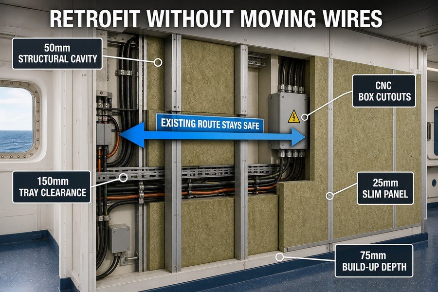
When you lead an interior refit project, keeping the old wires safe saves time and money. Buying good panels from Asia is only the first step. You also must plan how these new materials fit over the existing ship wiring. Let us look closely at how different spacing choices help you protect the ship electrical system.
What Cavity Space Behind Retrofit Wall Panels Accommodates Existing Cable Runs?
Thick cable bundles behind panels often get crushed. A tight space causes electrical faults and fails inspections. Discover the exact gap you need to keep wires safe.
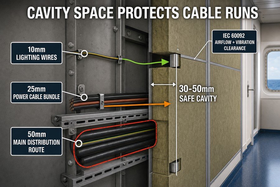
To safely accommodate existing cable runs, you must leave a 30mm to 50mm cavity space behind retrofit wall panels. This space includes a 10mm gap for standard lighting wires, a 25mm gap for bundled power cables, and a 50mm gap for heavy main distribution routes, following IEC 60092 standards.
Space Requirements for Standard Lighting and Power Wires
As a marine outfitting specialist at Magellan Marine, I see many buyers focus only on panel prices. They forget about the space needed behind the panel. If you buy a cheap panel and install it too close to the steel wall, you will crush the wires. You need a 10mm gap for standard lighting wires.1 These wires are thin. But they still need air to stay cool2. If the panel presses against them, the heat builds up over time. This breaks the wire insulation.3 For bundled power cables, you need a larger 25mm gap. Cabin power lines carry more current. They get hotter. The IEC 60092 standard tells us we must let air flow around these bundles.4 A 25mm gap gives enough room so the cables do not rub against the rough steel hull when the ship vibrates. I always advise my clients to check their old cabin drawings. You must know if your lighting and power wires run together or separate.
Clearance Rules for Heavy Main Distribution Routes
Heavy main distribution routes need the most space. You must leave a full 50mm gap for these thick cable paths. These main lines feed power to many cabins. They are heavy and hard to move. You cannot simply push them out of the way when you install a new marine wall panel. If you squeeze a heavy distribution route, you risk a major short circuit. The 30mm to 50mm total cavity space keeps everything safe.
| Cable Route Type | Required Gap Size | Standard Source | Risk of Tight Cavity |
|---|---|---|---|
| Standard Lighting Wires | 10mm | IEC 60092-352 | Insulation heat damage |
| Bundled Power Cables | 25mm | IEC 60092-352 | Vibration friction |
| Heavy Distribution Routes | 50mm | IEC 60092-352 | Major short circuit |
When you order your panels, you must buy the right mounting profiles. The metal profiles hold the panel away from the steel bulkhead. If your profiles are too shallow, you lose your cavity space. Good planning here saves you from tearing down the wall later.
How to Fit Retrofit Marine Wall Panels Around Fixed Electrical Junction Boxes?
Moving a fixed junction box is very costly. Cutting panels wrong leaves ugly gaps or breaks fire rules. Learn how to fit new walls perfectly around existing boxes.
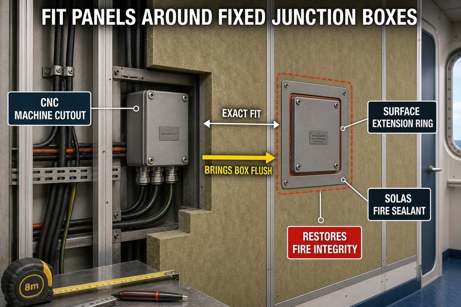
You can fit retrofit marine wall panels around fixed junction boxes by using three methods: creating precise CNC machine cutouts for exact fit, using surface-mounted extension rings to bring the box flush, and applying SOLAS-approved fire-resistant silicone sealants to fill any minor gaps, ensuring A-class or B-class fire integrity.
Creating Exact Fits with CNC Machine Cutouts
Old junction boxes are welded to the ship steel. You cannot just cut them out. When you buy marine wall panels from a factory in China or Vietnam, you must manage the cutouts. The best method is using precise CNC machine cutouts5. You measure the junction box locations on the ship. You send these exact drawings to the panel factory. The factory uses a computer to cut the holes. This gives an exact fit. Manual cutting at the shipyard is risky. Workers often cut the hole too big. A big hole looks bad and ruins the fire rating.6 I always tell buyers to spend a little more on factory CNC cutting. It saves high labor costs in European or American shipyards. The panels arrive ready to mount right over the old junction boxes.
Applying Extension Rings and SOLAS-Approved Sealants
Sometimes the new panel is thicker than the old one. The old junction box now sits too deep inside the wall. You cannot leave it like this. You must use surface-mounted extension rings. These metal rings screw into the old box. They bring the electrical connection flush with the new panel surface.7 This keeps the wiring safe and accessible. But even with CNC cutouts and extension rings, tiny gaps can happen. You must apply SOLAS-approved fire-resistant silicone sealants to fill any minor gaps. Regular silicone is not allowed on ships. It will burn. SOLAS Chapter II-2 rules say every hole in a fire wall must be sealed.8 The fire-resistant sealant stops smoke and flames from passing through the panel joint.
| Fitting Method | Application Time | Material Cost | Purpose for Junction Boxes |
|---|---|---|---|
| CNC Machine Cutouts | High (Pre-planning) | Low | Ensures an exact, clean fit |
| Extension Rings | Medium | Medium | Brings recessed boxes flush |
| SOLAS Fire Sealants | Low | Medium | Restores fire-class integrity |
Using all three methods ensures your retrofit project passes inspection. You get a clean look, safe wiring, and full fire compliance.
Why Do Thicker Retrofit Wall Panels Obstruct Existing Socket Outlets?
Thicker fire panels push the wall surface out. Your old socket outlets end up buried deep inside the wall. Understand why this happens and how to avoid it.
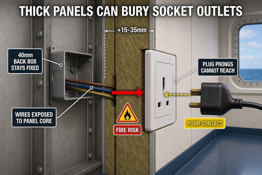
Thicker retrofit wall panels obstruct existing socket outlets because they increase the total wall depth by 15mm to 35mm. This buries standard 40mm deep electrical back boxes, creates a fire risk by exposing internal wiring to the panel core, and prevents standard plug prongs from reaching the electrical contacts.
How Wall Depth Increases Bury Standard Electrical Back Boxes
Many buyers want to improve cabin sound and fire ratings. So they buy thicker panels. An old B-15 panel might be 25mm thick. A new A-30 panel can be 50mm thick.9 This increases the total wall depth by 15mm to 35mm. When the wall gets thicker, the front surface moves away from the steel bulkhead. The problem is your existing standard 40mm deep electrical back boxes stay in the same place. They are fixed to the steel. Now, your back boxes are buried deep inside the new wall. You cannot simply screw the socket faceplate onto the new panel. The screws will not reach the box. The whole assembly becomes unstable. I see this mistake often. Procurement officers buy thicker panels to save money on other insulation. But they forget the extra cost of fixing buried electrical sockets.
Fire Risks and Plug Connection Issues from Deep Sockets
When a back box is buried, the internal wiring crosses through the open core of the thick panel. This creates a severe fire risk by exposing internal wiring to the panel core. If a wire sparks, the fire can spread inside the panel.10 Marine regulations demand that all electrical joints stay fully inside a steel or fire-rated box.11 Also, a deep socket creates connection problems. A buried socket prevents standard plug prongs from reaching the electrical contacts.12 The plastic faceplate might bend or snap. The user cannot plug in their laptop or heater safely.
| Wall Element | Old Installation | New Thick Panel Retrofit | Resulting Problem |
|---|---|---|---|
| Wall Depth Increase | 0mm | +15mm to +35mm | Pushes panel face outward |
| Back Box Position | Flush with wall | Buried 15-35mm deep | Faceplate cannot attach |
| Wire Exposure | Fully enclosed | Exposed to panel core | High fire risk (SOLAS violation) |
| Plug Prongs | Full contact | Partial or no contact | Sparks and poor connection |
You must order special deep back boxes or extension collars before you start. Knowing how panel thickness changes the room dimensions is key to a good refit.
How to Maintain Cable Tray Clearance When Installing Replacement Marine Wall Panels?
New panels can easily press against ceiling cable trays. This blocks airflow and makes future wire checks impossible. See how to keep the right distance during installation.
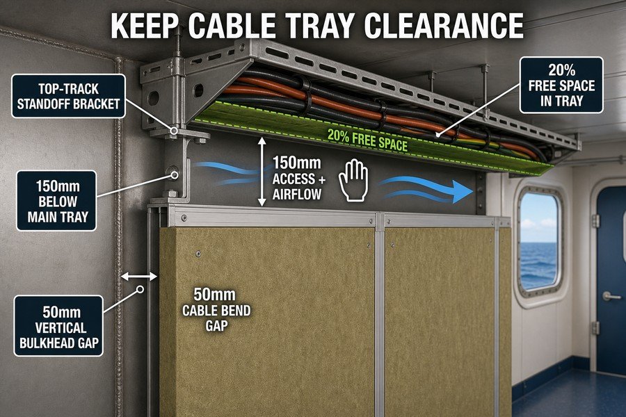
To maintain cable tray clearance, you must use a top-track standoff bracket, install panels at least 150mm below main ceiling trays, leave a 50mm gap from vertical bulkheads, and ensure 20% free space within the tray itself. This complies with standard marine electrical ventilation and maintenance access rules.
Using Top-Track Standoff Brackets and Vertical Gaps
Ship ceilings hide many cable trays. When you install new wall panels, the top edge meets the ceiling system. If you just push the wall panel up, you can crush the cables. You must use a top-track standoff bracket13. This metal bracket holds the top of the wall panel secure. It creates a hard stop so the panel cannot go too high. It protects the tray above. You also need to control the space behind the wall. You must leave a 50mm gap from vertical bulkheads14. This vertical gap lets the wall cables run up to the ceiling tray without bending too sharply. If you bend a thick marine cable too tight, the internal copper breaks. The 50mm vertical gap prevents this stress. I always check the bracket designs before my clients order them. A good bracket makes the shipyard workers install the panels correctly every time.
Ensuring Ceiling Tray Clearance and Free Space Capacity
You must install the ceiling panels at least 150mm below main ceiling trays. The IEC 60092 standard requires this space for heat to escape. Marine cables get hot under heavy load. If you close the gap, the heat stays trapped. This lowers the cable life. The 150mm clearance also allows an electrician to reach their hand inside for future checks. Inside the tray, you must ensure 20% free space within the tray itself. You cannot pack the tray completely full of cables. The 20% free space rule gives room for air flow and future wire additions.
| Clearance Parameter | Minimum Required Value | Purpose for Marine Retrofit |
|---|---|---|
| Top-Track Standoff Bracket | Custom fit | Stops wall panel from crushing trays |
| Vertical Bulkhead Gap | 50mm | Prevents sharp cable bends |
| Below Main Ceiling Tray | 150mm | Allows heat venting and hand access |
| Tray Internal Free Space | 20% | Future wiring and air circulation |
Managing these clearances takes good communication between your interior team and the electrical team. Buy the right brackets to force the correct spacing.
What Marine Wall Panel Build-Up Depth Permits Rewiring During Cabin Retrofits?
Adding new wires later is very hard if the wall is too tight. A bad panel design traps the electrical system. Find the right build-up depth for easy rewiring.
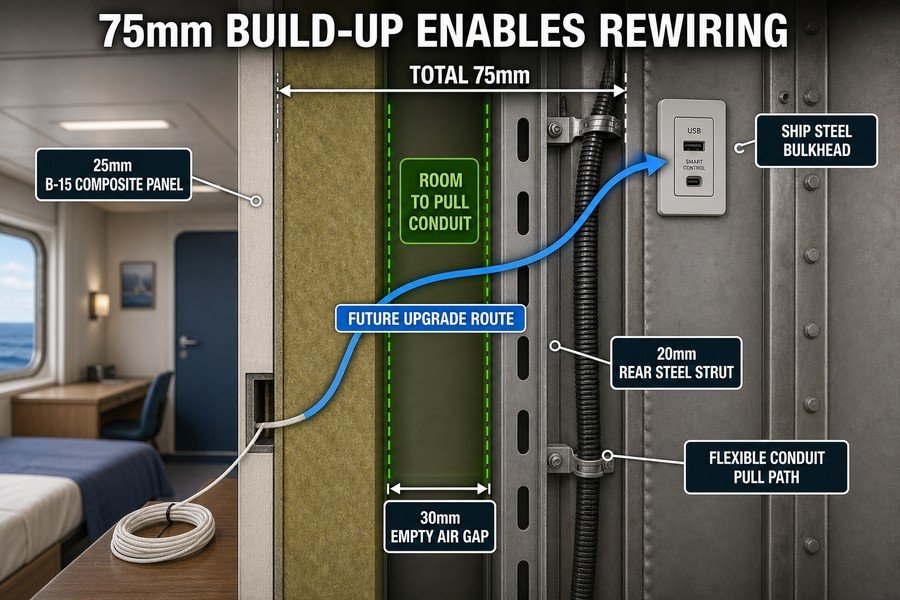
A total build-up depth of 75mm permits rewiring during cabin retrofits. This depth consists of a 25mm B-15 class composite panel, a 30mm empty middle air gap for pulling flexible conduits, and a 20mm rear steel mounting strut, giving you enough room for future electrical upgrades and maintenance.
Breakdown of the 25mm Panel and 20mm Mounting Strut
When shipowners plan a refit, they often want to add new USB sockets or smart cabin controls later. You need a wall system that allows this. A total build-up depth of 75mm works best. Let us break this down. First, you have the 25mm B-15 class composite panel15. This is your standard fire-rated cabin partition. It gives a nice finish and stops fire. It is thin but strong. On the back, against the ship hull, you install a 20mm rear steel mounting strut16. This strut gives the wall its strength. It holds the heavy panel in place during rough seas. These two parts take up 45mm of space. Some people try to save cabin floor space by pushing the panel right against the strut. But this is a bad idea. It leaves no room for the electrician. You save one inch of floor space, but you make future work impossible.
The Role of the 30mm Air Gap in Future Electrical Upgrades
The secret to a smart retrofit is the middle space. You must leave a 30mm empty middle air gap for pulling flexible conduits17. This gap sits between the 25mm panel and the 20mm strut. When you want to add a new wire, you tie it to a pull-string and pull it through this 30mm space. The flexible conduit slides easily without snagging on the steel structure. This gives you enough room for future electrical upgrades and maintenance. Shipyards love this design. It means they can close the walls early in the project. The electricians can come in later and pull their wires. It speeds up the whole schedule.
| Component of Wall System | Depth | Material Function |
|---|---|---|
| Composite Panel | 25mm | B-15 fire protection and room finish |
| Middle Air Gap | 30mm | Space for pulling new flexible conduits |
| Mounting Strut | 20mm | Secures panel to ship steel structure |
| Total Build-Up Depth | 75mm | Optimal depth for easy cabin rewiring |
Using a 75mm build-up depth balances the need for cabin space with the reality of marine electrical work. It is the smartest choice for standard accommodation areas.
Conclusion
Refitting marine panels without hurting wires needs good planning. Control your cavity space, manage wall depths, and respect electrical clearances. Your projects will stay safe, legal, and very profitable.
-
"(PDF) Electrical installations in ships – Part 352: Choice and ...", https://www.academia.edu/28714945/Electrical_installations_in_ships_Part_352_Choice_and_installation_of_electrical_cables. IEC 60092-352 addresses shipboard cable installation practices, including routing, support, and protection considerations for electrical cables in marine environments. Evidence role: general_support; source type: institution. Supports: Standard lighting wires require a 10 mm clearance behind marine wall panels.. Scope note: The source may support minimum installation clearances only if the article’s 10 mm figure is explicitly present in the standard or an applicable classification rule; otherwise it provides contextual support rather than direct verification of this exact number. ↩
-
"[PDF] Ampacity Derating and Cable Functionality for - Raceway Fire Barriers", https://www.nrc.gov/docs/ml0037/ml003745784.pdf. Electrical cable ampacity and installation guidance commonly account for heat dissipation conditions, including grouping, enclosure, and ambient environment, because insufficient heat removal can raise conductor temperature. Evidence role: mechanism; source type: government. Supports: Even thin lighting wires need adequate surrounding space or ventilation to dissipate heat.. Scope note: This supports the thermal mechanism generally; it does not by itself prove the article’s specific clearance dimensions for marine wall panels. ↩
-
"[PDF] Correlation of Electrical Cable Failure with Mechanical Degradation.", https://www.nrc.gov/docs/ML0622/ML062260360.pdf. Cable ageing research shows that elevated temperature accelerates degradation of polymeric cable insulation and can reduce dielectric and mechanical integrity over time. Evidence role: mechanism; source type: paper. Supports: Heat buildup over time can damage or degrade wire insulation.. Scope note: The evidence supports heat-related insulation degradation generally; the exact failure rate depends on insulation material, temperature, loading, and marine exposure conditions. ↩
-
"(PDF) Electrical installations in ships – Part 352: Choice and ...", https://www.academia.edu/28714945/Electrical_installations_in_ships_Part_352_Choice_and_installation_of_electrical_cables. IEC 60092 standards for electrical installations in ships provide rules for cable installation and current-carrying capacity, where grouping and installation conditions affect permissible loading and thermal performance. Evidence role: expert_consensus; source type: institution. Supports: IEC 60092 provides shipboard electrical installation requirements relevant to airflow, grouping, and thermal management around cable bundles.. Scope note: This supports the relevance of IEC 60092 to shipboard cable installation and thermal derating; direct support for the phrase “must let air flow around these bundles” requires a section that explicitly addresses ventilation or spacing for bundled cables. ↩
-
"[PDF] Dynamic evaluation of spatial CNC contouring accuracy", https://mtrc.utk.edu/wp-content/uploads/sites/45/2019/09/dynamic_spatial_accuracy.pdf. A manufacturing engineering source describing computer numerical control machining can support that CNC processes use programmed toolpaths to produce repeatable, dimensionally controlled cuts; this supports the rationale for prefabricated panel openings, though it does not prove the accuracy of any particular factory or project. Evidence role: mechanism; source type: education. Supports: Factory CNC cutting is a suitable method for producing precise cutouts in marine wall panels.. Scope note: Contextual support only; actual fit depends on measurement accuracy, machine calibration, materials, and quality control. ↩
-
"What Is the Purpose and Scope of the IMO FTP Code-", https://magellanmarinetech.com/what-purpose-scope-of-imo-ftp-code/. SOLAS and IMO fire-test guidance for fire-resisting divisions can support that penetrations and openings must be arranged so the division’s required fire integrity is maintained; this supports the fire-rating concern for oversized or unsealed cutouts, but it does not evaluate the visual quality of the opening. Evidence role: mechanism; source type: institution. Supports: Oversized or improperly sealed openings in a fire-rated ship wall panel can compromise the fire integrity of the division.. Scope note: Does not support the aesthetic statement that a large hole 'looks bad'; it supports only the fire-integrity aspect. ↩
-
"Electrical standard requirements concerning covers for ... - OSHA", http://www.osha.gov/laws-regs/standardinterpretations/2002-10-03. Electrical installation guidance on outlet-box extensions can support that extension rings are used where a finished surface is built out, bringing the box opening to the new surface and preserving access to wiring; this is general electrical-installation evidence and may not address ship-class approval requirements. Evidence role: definition; source type: government. Supports: Extension rings are used to adapt recessed electrical boxes so the connection remains flush with the finished wall surface and accessible.. Scope note: General support for the function of extension rings; shipboard installations may also require class-society or marine electrical compliance. ↩
-
"Summary of SOLAS chapter II-2 - International Maritime Organization", https://www.imo.org/en/ourwork/safety/pages/summaryofsolaschapterii-2-default.aspx. SOLAS Chapter II-2 provisions on structural fire protection can support that penetrations through fire-resisting divisions must be arranged to preserve the division’s fire resistance and limit smoke or flame spread; this substantiates the sealing requirement in principle, although the exact wording may not state 'every hole' in those terms. Evidence role: expert_consensus; source type: institution. Supports: Openings or penetrations in ship fire divisions must be sealed or protected so the required fire integrity is maintained.. Scope note: Supports the regulatory principle rather than the article’s simplified wording. ↩
-
"What Is the Purpose and Scope of the IMO FTP Code-", https://magellanmarinetech.com/what-purpose-scope-of-imo-ftp-code/. SOLAS fire-test classifications define B-15 and A-30 divisions by their ability to limit temperature rise for specified durations, while type-approval certificates or test reports can document that certified marine wall panels are manufactured in differing thicknesses for those classes. Evidence role: historical_context; source type: institution. Supports: B-15 and A-30 marine panels differ in fire-rating class, and real certified panels may have different thicknesses such as approximately 25 mm and 50 mm.. Scope note: SOLAS supports the meaning of the fire ratings directly, but individual panel thicknesses vary by manufacturer and certification. ↩
-
"24 CFR Part 3280 Subpart C -- Fire Safety - eCFR", https://www.ecfr.gov/current/title-24/subtitle-B/chapter-XX/part-3280/subpart-C. Fire-safety guidance on concealed cavities and electrical faults recognizes that unprotected wiring and penetrations can contribute to ignition and hidden fire spread, which supports treating exposed wiring inside a panel core as a fire-propagation hazard. Evidence role: mechanism; source type: government. Supports: Exposed or faulting electrical wiring in a concealed wall or panel cavity can create a pathway for ignition and hidden fire spread.. Scope note: Such sources support the fire-spread mechanism generally; the actual risk depends on cable condition, panel-core combustibility, fire stopping, and installation details. ↩
-
"Update to Electrical Engineering Regulations - Regulations.gov", https://www.regulations.gov/document/USCG-2020-0075-0001. Marine electrical rules and ship-classification standards generally require cable connections and joints to be made in suitable enclosures or junction boxes, supporting the need to keep electrical terminations protected rather than exposed within wall cavities. Evidence role: expert_consensus; source type: institution. Supports: Marine electrical installations require electrical joints and terminations to be enclosed in suitable protective boxes rather than left exposed in panel cores.. Scope note: The exact material and fire-rating requirement depends on vessel type, flag state, classification society, and the surrounding fire division. ↩
-
"BS 1363 - Wikipedia", https://en.wikipedia.org/wiki/BS_1363. Plug-and-socket standards specify plug-pin dimensions and socket contact arrangements, supporting the principle that socket outlets must be installed so the plug can achieve the intended mechanical insertion depth and electrical contact engagement. Evidence role: mechanism; source type: institution. Supports: A socket recessed behind the finished surface may prevent a standard plug from reaching the designed contact engagement depth.. Scope note: The standard establishes plug and socket geometry, but it may not explicitly discuss the retrofit scenario of a socket recessed behind an added wall panel. ↩
-
"Update to Electrical Engineering Regulations - Regulations.gov", https://www.regulations.gov/document/USCG-2020-0075-0001. Shipboard cable-installation guidance treats cable trays and adjacent structures as protected service routes that require mechanical clearance from later interior work; this supports the use of a standoff or equivalent stop to prevent panels from intruding into tray space. Evidence role: general_support; source type: institution. Supports: A top-track standoff bracket is needed to stop new wall panels from being pushed high enough to crush or interfere with cable trays above.. Scope note: The source may support the clearance/protection principle rather than naming this exact bracket design. ↩
-
"(PDF) Electrical installations in ships – Part 352: Choice and ...", https://www.academia.edu/28714945/Electrical_installations_in_ships_Part_352_Choice_and_installation_of_electrical_cables. IEC 60092-352 and related marine cable-installation guidance specify that shipboard cables must be routed without exceeding minimum bending-radius limits; this provides technical context for requiring a vertical clearance behind panels. Evidence role: expert_consensus; source type: institution. Supports: A vertical bulkhead gap is needed so wall cables can route upward without being bent too sharply.. Scope note: Minimum bending radius is usually expressed as a multiple of cable diameter, so a fixed 50 mm gap is only supported if it is validated for the cable sizes used. ↩
-
"What Is the Purpose and Scope of the IMO FTP Code-", https://magellanmarinetech.com/what-purpose-scope-of-imo-ftp-code/. A citation to SOLAS/IMO fire-test terminology would support that B-class divisions are regulated marine fire divisions and that the “15” designation refers to a specified insulation performance period in standard fire testing. Evidence role: definition; source type: institution. Supports: A 25mm B-15 class composite panel is a fire-rated cabin partition component.. Scope note: Such a source would define the B-15 rating but may not verify that a 25 mm composite panel is standard for all cabin partitions. ↩
-
"How to choose the right marine wall panels for marine interior ...", https://magellanmarinetech.com/how-choose-right-marine-wall-panels-for-marine-interior-projects/. A citation to ship accommodation or class-society structural guidance would support the general role of steel framing or supports in attaching interior panels to the vessel structure and resisting shipboard vibration and motion loads. Evidence role: mechanism; source type: institution. Supports: A rear steel mounting strut provides structural support for the cabin wall panel and helps secure it to the ship structure.. Scope note: The source may support the need for secure structural fixing generally rather than proving that a 20 mm strut is required in every installation. ↩
-
"Update to Electrical Engineering Regulations - Federal Register", https://www.federalregister.gov/documents/2023/03/16/2023-04370/update-to-electrical-engineering-regulations. A citation to electrical installation guidance for ships or buildings would support that accessible voids, conduits, and pull spaces facilitate later cable installation and maintenance. Evidence role: general_support; source type: government. Supports: Leaving an empty middle air gap can make it easier to pull flexible conduits for future wiring upgrades.. Scope note: The evidence would likely support the principle of providing routing space, while the exact 30 mm dimension may remain a project-specific design choice unless a detailed standard is found. ↩