Upgrading your ship's interior but worried about hidden retrofit delays? Failing to check site conditions causes massive cost overruns. Let us look at what you must check first.
A complete site assessment for marine panel replacement must evaluate six critical conditions: pre-installation survey data for interface matching, existing ceiling heights, ceiling void clearances for utilities, bulkhead structural integrity, available drydock schedule, and the operational status of live ship systems.
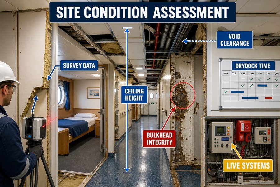
Missing any of these steps will hurt your project timeline and budget. I will break down each critical check so your next outfitting project runs smoothly from start to finish.
How Do Pre-Installation Surveys Reduce Marine Wall and Ceiling Panel Interface Errors?
Interface mismatches between old frames and new panels ruin tight retrofit budgets. You lose money when workers wait for new parts. Here is how surveys fix this problem.
Pre-installation surveys reduce interface errors by capturing precise 3D laser scan data, identifying existing deck unevenness, mapping out concealed cable routes, and confirming exact grid spacing. This complete four-point mapping ensures new marine wall and ceiling panels align perfectly with legacy ship structures without on-site cutting.
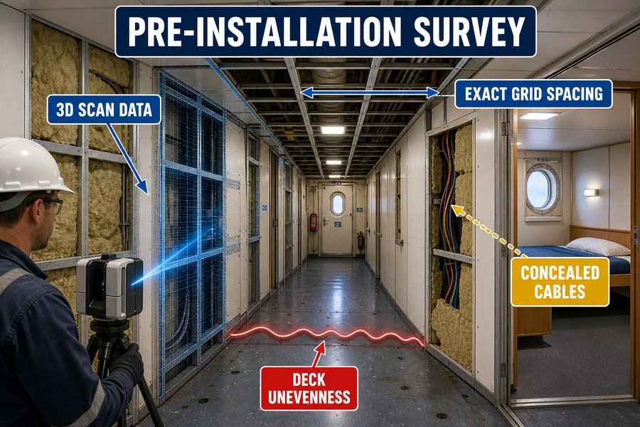
I remember a project in a Vietnam shipyard where a client skipped a proper survey to save a few dollars. When the new wall panels arrived, nothing fit. The workers spent a whole week cutting panels by hand. We can avoid this problem by checking the exact conditions of the site first. We must look at four specific things: 3D scan data, deck unevenness, hidden cable routes, and the exact grid spacing.
Using 3D Laser Scanning to Capture Data and Measure Deck Unevenness
The first step in a survey is capturing precise 3D laser scan data. Modern marine surveys use 3D laser scanners to create a digital model of the cabin space. These scanners have a very high accuracy. According to ISO 12858 standards for survey instruments, a good scanner gives an accuracy of ±2 millimeters1. This exact data tells the factory exactly how big to make the panels. You do not need to guess.
Next, we use this 3D data to identify existing deck unevenness. Ships bend and flex over time. The steel deck is rarely perfectly flat. Standard shipbuilding rules allow a maximum deck deviation of 3 millimeters per meter. If the deck bends more than this, a standard bottom track for a marine wall panel will not sit flat. The panel will look crooked. By finding this unevenness early, we can order special adjustable bottom tracks to fix the gap.
Mapping Concealed Cable Routes and Confirming Exact Grid Spacing
The survey must also map out concealed cable routes. Old ships hide many electrical wires behind the old panels. If you do not know where these wires are, workers might drill into them during installation. SOLAS (Safety of Life at Sea) Chapter II-1 requires all primary cable routes to remain safe and accessible2. We use wire trackers to mark these routes on the drawing. This way, we cut the access holes in the new panels at the factory, not on the ship.
Finally, we must confirm exact grid spacing. Most modern marine ceiling panels use a standard grid spacing of 600 millimeters or 1200 millimeters3. However, a 20-year-old ship might use a custom spacing like 585 millimeters. If you order 600-millimeter panels for a 585-millimeter grid, they will not fit. You must measure the old grid distance exactly. If it is different, you must either order custom-sized ceiling panels or buy a completely new suspension grid system.
| Survey Action | Data Captured | Tolerance / Standard Requirement | Action Taken Before Panel Order |
|---|---|---|---|
| 3D Laser Scanning | Room dimensions | ±2 mm accuracy (ISO 12858) | Order panels to exact room size |
| Deck Measurement | Deck unevenness | Max 3 mm per meter deviation | Order adjustable bottom U-tracks |
| Cable Tracking | Concealed cable routes | SOLAS Chapter II-1 safety rules | Pre-cut access holes in factory |
| Grid Measurement | Exact grid spacing | 600 mm or 1200 mm standard | Order matching panels or new grid |
How Do Existing Ceiling Heights Dictate Marine Ceiling Panel Replacement Feasibility?
Low ceiling heights make cabins feel cramped and block new ventilation systems. Ignoring current deck-to-deck limits leads to strict regulatory failures. Let us solve this height problem safely.
Existing ceiling heights dictate feasibility through three primary constraints: mandated minimum regulatory headroom limits, the vertical space needed for overlapping panel joints, and the clearance required for new fire-rated insulation. Retrofits must balance these three factors to maintain passenger comfort and strict maritime safety compliance.
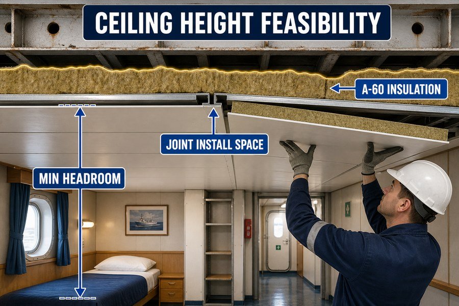
When I visit old ships, the deck-to-deck steel height is often very low. The shipyard wants to add thick modern insulation and large new lights. But the space simply is not there. You cannot just lower the ceiling panel as much as you want. You must balance three strict limits: the legal headroom rules, the panel joint space, and the fire insulation thickness.
Complying with Minimum Regulatory Headroom Limits
The most important limit is the mandated minimum regulatory headroom limit. Maritime law protects the living conditions of the crew and passengers. According to the ILO MLC (Maritime Labour Convention, 2006), the clear headroom in a crew cabin must not be less than 2030 millimeters. On some very old ships built before these rules, local authorities might accept a minimum of 1980 millimeters, but you must ask for special permission first.
If the distance from the bare steel floor to the bare steel ceiling is only 2150 millimeters, you have a very big problem. You only have 120 millimeters of total space for the floor covering, the ceiling suspension system, and the ceiling panel itself. If you install a ceiling that drops the room height to 2000 millimeters, the ship will fail its inspection. You will have to tear everything down and start over.
Managing Vertical Space for Panel Joints and Fire Insulation
Next, you must calculate the vertical space needed for overlapping panel joints. You do not just push a ceiling panel up; you have to slide it into a metal carrier profile. A standard C-strip or linear ceiling system requires about 15 to 25 millimeters of vertical pushing space4 so the installer can lock the joint in place. If the ceiling is too close to the steel pipes above, the worker's hands cannot fit to push the panel up.
Lastly, you must measure the clearance required for new fire-rated insulation. Old ships often need fire safety upgrades. If the deck above requires an A-60 fire rating, you must add thick insulation. According to IMO FTP Code regulations, standard A-60 marine rockwool insulation is usually 50 to 75 millimeters thick5. It weighs around 80 to 100 kg/m³. You must place this rockwool between the steel deck and your new ceiling panel. This thick layer eats up your limited height very fast.
| Height Constraint Factor | Minimum Requirement / Dimension | Regulatory Source | Impact on Retrofit Design |
|---|---|---|---|
| Clear Cabin Headroom | 2030 mm | ILO MLC (2006) | Limits how low the ceiling can hang |
| Panel Joint Overlap | 15 - 25 mm | Manufacturer Specs | Needs manual working space |
| A-60 Fire Insulation | 50 - 75 mm thick | IMO FTP Code | Reduces available void space |
| Typical Old Deck Height | 2150 - 2200 mm | Legacy Ship Designs | Forces use of low-profile panels |
How Does Ceiling Void Clearance Determine Marine Ceiling Panel Retrofit Viability?
You buy beautiful ceiling panels but realize the hidden space is too small for modern air ducts. Your installation stops immediately. Let us check the hidden space.
Ceiling void clearance determines retrofit viability by limiting the physical space available for four hidden elements: larger modern HVAC ductwork, updated sprinkler pipe networks, thick electrical cable trays, and suspension bracket systems. A shallow void forces designers to use custom low-profile panels or reroute major utility lines.
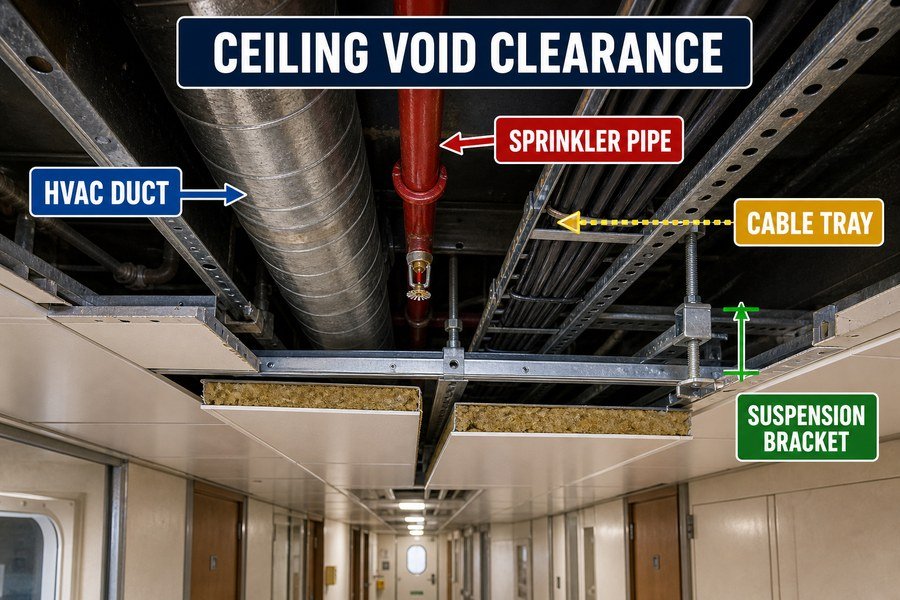
The ceiling void is the dark, empty space between the decorative ceiling panel and the steel deck above it. People usually ignore this space until they try to fit new pipes inside it. I always tell my clients to open a few old panels and look inside with a flashlight. You must find out if you have enough space for four major systems: the HVAC ducts, the sprinkler pipes, the electrical cable trays, and the suspension brackets.
Accommodating Modern HVAC Ductwork and Sprinkler Pipe Networks
First, we must look at the larger modern HVAC ductwork. Old ships had very poor air conditioning. Today, shipowners want strong, fresh air in every cabin. To move more air, the metal HVAC ducts must be bigger. A modern marine spiral duct for a cabin usually needs a diameter of 150 to 200 millimeters. If your ceiling void is only 100 millimeters deep, the new duct simply will not fit. You will have to lower the ceiling or use flat, custom-made rectangular ducts, which cost a lot of money.
Second, you must check the updated sprinkler pipe networks. Fire safety is much stricter now. You must install water sprinkler pipes above the ceiling. According to NFPA 13 Marine standards, the sprinkler pipes themselves are usually 25 to 50 millimeters wide.6 However, you must also leave a clearance of at least 50 millimeters around the pipe for maintenance and to prevent water condensation from ruining the metal ceiling panels.
Fitting Electrical Cable Trays and Suspension Bracket Systems
Third, you must measure the space for thick electrical cable trays. Modern ships use much more electricity for Wi-Fi, big televisions, and led lights. The main power cables run in metal trays above the ceiling in the corridor. A standard marine cable tray requires a vertical space of at least 100 millimeters.7 If these trays block the path, you cannot install your ceiling grid in a straight line.
Finally, you must leave room for the suspension bracket systems. The ceiling panels hang from the steel deck on metal rods or brackets. To make the ceiling perfectly level, these brackets need an adjustment range. A standard galvanized suspension bracket needs 30 to 50 millimeters of vertical space8 so the installer can spin the nut and adjust the height. If the void is too tight, workers cannot level the ceiling, and the final look will be wavy and cheap.
| Hidden Element in Void | Typical Vertical Space Needed | Standard or Guideline | Solution if Void is Too Shallow |
|---|---|---|---|
| HVAC Spiral Ductwork | 150 - 200 mm | HVAC Design Specs | Use flat rectangular custom ducts |
| Sprinkler Pipe Network | 25 - 50 mm + clearance | NFPA 13 Marine | Reroute pipes to ship corridors |
| Electrical Cable Trays | 100 mm minimum | Shipyard Electrical Code | Condense wires or move trays |
| Suspension Brackets | 30 - 50 mm adjustment | Manufacturer Specs | Use direct-mount screw systems |
How Does Bulkhead Structural Integrity Dictate Marine Wall Panel Planning?
Bolting new heavy fire panels onto rusty steel bulkheads is dangerous. Weak steel cannot hold the weight during rough seas. Here is how to assess the metal first.
Bulkhead structural integrity dictates panel planning through three critical checks: measuring steel thickness loss from corrosion, testing the load-bearing capacity of existing vertical stiffeners, and checking weld joint soundness. Failing these three checks means the shipyard must perform major steel renewals before any interior outfitting begins.
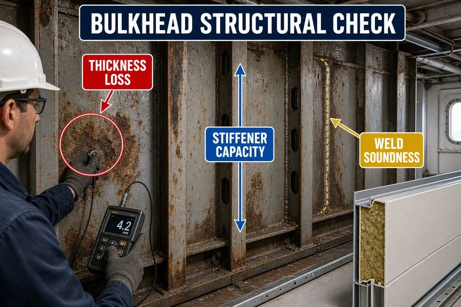
A beautiful new wall panel means nothing if the steel wall behind it is rotting away. Ship vibrations will shake loose any panel attached to weak steel.9 Before you order marine wall panels, you must check the bare steel bulkhead. I have seen clients try to drill panel tracks into rusted steel, only to watch the screws pull right out. You must check three structural points: steel thickness loss, stiffener capacity, and weld joint soundness.
Measuring Steel Thickness Loss from Corrosion in Marine Bulkheads
The biggest enemy of a ship is rust. Over 15 or 20 years, saltwater and condensation eat the steel bulkheads from the inside out.10 The first critical check is measuring steel thickness loss from corrosion. Surveyors use an Ultrasonic Thickness (UT) gauge to check the steel plate.11 International Association of Classification Societies (IACS) rules state that if the steel thickness loss exceeds 20% to 25% of the original built thickness, the steel is no longer safe12.
If the steel is too thin, it cannot support the weight of new marine interior panels. A standard 50-millimeter rockwool core marine wall panel weighs about 15 to 18 kilograms per square meter.13 A whole cabin wall can weigh hundreds of kilograms. If the steel fails the UT test, the shipyard must cut out the rusty steel and weld in new plates. This steel renewal takes weeks. You must not start your panel planning until the steel is fully repaired and painted.
Testing Load-Bearing Capacity of Stiffeners and Weld Joint Soundness
The next check is testing the load-bearing capacity of existing vertical stiffeners. Bulkheads are not just flat plates; they have vertical metal beams called stiffeners welded to them to provide strength. These stiffeners are usually spaced every 600 millimeters. We attach the U-profiles for the wall panels directly to these stiffeners. If the stiffeners are bent from cargo damage or weakened by rust, they cannot bear the load of the heavy A-class fire panels.
Finally, you must check the weld joint soundness. The places where the stiffeners meet the deck are under extreme stress when the ship rolls in the waves. We use Non-Destructive Testing (NDT), like magnetic particle testing, to find invisible cracks in the old welds. If the welds are cracked, attaching a heavy wall panel will cause the weld to snap completely during a storm. All welds must be fully repaired by certified welders before you install the bottom tracks of your marine panels.
| Structural Check | Testing Method | Rejection Criteria | Impact on Panel Installation |
|---|---|---|---|
| Steel Thickness Loss | Ultrasonic Testing (UT) | > 20-25% thickness loss (IACS) | Stop project for steel renewal |
| Stiffener Load Capacity | Visual & Load Check | Bent, rusted, or missing beams | Cannot mount heavy A-Class panels |
| Weld Joint Soundness | Magnetic Particle Testing | Visible cracks or fatigue | Weld will break under panel weight |
| Panel Weight Bearing | Engineering Calculation | Steel cannot hold 18 kg/m² | Must upgrade steel support frames |
How Does Available Drydock Time Restrict Marine Wall and Ceiling Panel Retrofit Scope?
Drydock days cost thousands of dollars per day. A slow panel retrofit delays the ship launch and eats your entire profit. We must manage the time tightly.
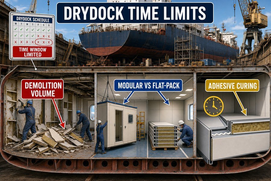
Available drydock time restricts retrofit scope by dictating three scheduling limits: the volume of old panel demolition possible, the feasibility of using prefabricated modular cabins versus flat-pack panels, and the time allowed for curing adhesives. Shorter drydock windows force buyers to choose fast-click installation systems over traditional wet-glue methods.
A beautiful new wall panel means nothing if the steel wall behind it is rotting away. Ship vibrations will shake loose any panel attached to weak steel.14 Before you order marine wall panels, you must check the bare steel bulkhead. I have seen clients try to drill panel tracks into rusted steel, only to watch the screws pull right out. You must check three structural points: steel thickness loss, stiffener capacity, and weld joint soundness.
Measuring Steel Thickness Loss from Corrosion in Marine Bulkheads
The biggest enemy of a ship is rust. Over 15 or 20 years, saltwater and condensation eat the steel bulkheads from the inside out.15 The first critical check is measuring steel thickness loss from corrosion. Surveyors use an Ultrasonic Thickness (UT) gauge to check the steel plate.16 International Association of Classification Societies (IACS) rules state that if the steel thickness loss exceeds 20% to 25% of the original built thickness, the steel is no longer safe17.
If the steel is too thin, it cannot support the weight of new marine interior panels. A standard 50-millimeter rockwool core marine wall panel weighs about 15 to 18 kilograms per square meter.18 A whole cabin wall can weigh hundreds of kilograms. If the steel fails the UT test, the shipyard must cut out the rusty steel and weld in new plates. This steel renewal takes weeks. You must not start your panel planning until the steel is fully repaired and painted.
Testing Load-Bearing Capacity of Stiffeners and Weld Joint Soundness
The next check is testing the load-bearing capacity of existing vertical stiffeners. Bulkheads are not just flat plates; they have vertical metal beams called stiffeners welded to them to provide strength. These stiffeners are usually spaced every 600 millimeters. We attach the U-profiles for the wall panels directly to these stiffeners. If the stiffeners are bent from cargo damage or weakened by rust, they cannot bear the load of the heavy A-class fire panels.
Finally, you must check the weld joint soundness. The places where the stiffeners meet the deck are under extreme stress when the ship rolls in the waves. We use Non-Destructive Testing (NDT), like magnetic particle testing, to find invisible cracks in the old welds. If the welds are cracked, attaching a heavy wall panel will cause the weld to snap completely during a storm. All welds must be fully repaired by certified welders before you install the bottom tracks of your marine panels.
| Structural Check | Testing Method | Rejection Criteria | Impact on Panel Installation |
|---|---|---|---|
| Steel Thickness Loss | Ultrasonic Testing (UT) | > 20-25% thickness loss (IACS) | Stop project for steel renewal |
| Stiffener Load Capacity | Visual & Load Check | Bent, rusted, or missing beams | Cannot mount heavy A-Class panels |
| Weld Joint Soundness | Magnetic Particle Testing | Visible cracks or fatigue | Weld will break under panel weight |
| Panel Weight Bearing | Engineering Calculation | Steel cannot hold 18 kg/m² | Must upgrade steel support frames |
How Do Live Ship Systems Dictate Marine Wall Panel Replacement Schedules?
Replacing panels while the ship keeps its power and water running is hard. Accidentally cutting a live wire causes serious fires. We must plan around active systems.
Live ship systems dictate replacement schedules through three operational limits: the necessity for temporary power shutdowns, the phased isolation of active fire suppression zones, and the rerouting of daily crew walkways. Installers must sequence panel work in small blocks to keep the vessel safe and functional during the retrofit.
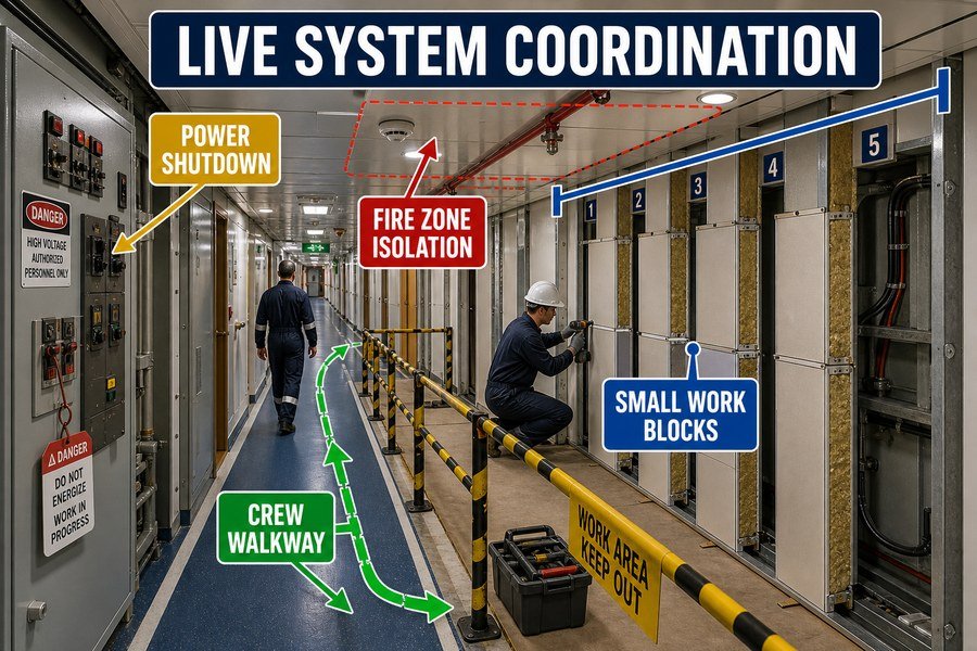
Sometimes, we must replace wall panels while the ship is still floating at the pier, with the crew still living on board. The ship's heart is still beating. You cannot just turn off all the lights and water for a month. Working around these active pipes and wires is very tricky. We must strictly control the schedule around three operational limits: power shutdowns, fire zone isolations, and crew walkways.
Managing Temporary Power Shutdowns and Rerouting Crew Walkways
The first major limit is the necessity for temporary power shutdowns. Behind the wall panels are live 220V or 110V electrical wires for the cabin lights and sockets19. A worker cutting an old metal panel with a saw can easily slice into a live wire, causing a deadly shock or a ship fire20. To stay safe, the chief engineer must shut off the power. But they will only let you shut down power in small blocks, maybe 5 cabins at a time, so the rest of the ship can keep working.
The next limit is the rerouting of daily crew walkways. Even during a retrofit, the crew needs to eat, sleep, and maintain the engines. Your panel installation materials cannot block the main corridors. According to SOLAS regulations, primary escape routes and walkways must maintain a minimum clear width of 800 millimeters at all times21. You must schedule your material deliveries so that heavy boxes of panels are moved into the cabins immediately, keeping the corridor clear for the crew.
Phasing the Isolation of Active Fire Suppression Zones
The final and most strict limit is the phased isolation of active fire suppression zones. Ships rely on automatic water sprinklers and smoke detectors22 to survive. When you remove a ceiling panel, you expose these delicate systems. Dust from cutting panels will trigger false fire alarms23. Therefore, you must cover the smoke detectors.
However, IMO MSC.1/Circ.1432 rules state you cannot blind the fire system for the whole ship at once24. You must perform a phased isolation. You isolate one small fire zone, replace the ceiling and wall panels in that zone, clean the dust, and turn the fire system back on. Only then can you move to the next zone. This zone-by-zone sequencing makes the project schedule much longer, but it is the only legal and safe way to replace panels on a live ship.
| Live System Constraint | Operational Limit | Regulatory Standard | Required Schedule Action |
|---|---|---|---|
| Electrical Power | Cannot shut down whole ship | Ship Safety Management | Work in small 5-cabin power blocks |
| Crew Walkways | Must keep escape paths clear | SOLAS 800 mm minimum width | Move panel boxes out of corridors |
| Fire Suppression | Cannot disable all alarms | IMO MSC.1/Circ.1432 | Isolate one fire zone at a time |
| HVAC Ventilation | Must keep crew air flowing | ILO MLC Airflow Rules | Tape ducts temporarily during work |
Conclusion
Checking all site conditions, from ceiling voids and structural steel to drydock schedules and live systems, ensures your panel replacement finishes on time. Smart planning saves money and keeps your marine interior project completely stress-free.
-
"Performance Evaluation of Terrestrial Laser Scanners - A Review", https://pmc.ncbi.nlm.nih.gov/articles/PMC8314184/. Peer-reviewed studies of terrestrial laser scanning report millimetre-level measurement accuracy under controlled conditions, supporting the plausibility of high-precision 3D survey data for fabrication; actual accuracy depends on scanner model, calibration, range, surface reflectivity, and point-cloud registration error. Evidence role: statistic; source type: paper. Supports: A good 3D laser scanner can provide approximately ±2 mm accuracy for survey measurements.. Scope note: The support is contextual unless the source tests the same scanner model and site workflow used in the shipyard. ↩
-
"International Convention for the Safety of Life at Sea (SOLAS), 1974", https://www.imo.org/en/about/conventions/pages/international-convention-for-the-safety-of-life-at-sea-(solas),-1974.aspx. SOLAS Chapter II-1 contains requirements for ship electrical installations and safety of essential services, supporting the need to protect cable routes during modification work; it may not state the article’s wording about all primary cable routes being accessible verbatim. Evidence role: general_support; source type: institution. Supports: SOLAS Chapter II-1 requires primary cable routes to remain safe and accessible.. Scope note: The citation would support the safety rationale for identifying cable routes, but the exact accessibility requirement may depend on flag-state rules, class rules, and the vessel’s approved electrical documentation. ↩
-
"[PDF] Suspended Grid Ceiling - SLC.gov", https://www.slc.gov/buildingservices/wp-content/uploads/sites/9/2023/06/Grid-Ceiling_ENG-2023.pdf. Suspended-ceiling standards and technical references describe common modular ceiling layouts based on 600 mm and 1200 mm modules, supporting the claim that these dimensions are standard grid spacings; this evidence is general to suspended ceiling systems and may not cover every marine ceiling product. Evidence role: definition; source type: institution. Supports: Most modern marine ceiling panels use a standard grid spacing of 600 millimeters or 1200 millimeters.. Scope note: The support is contextual unless the source specifically addresses marine ceiling panels rather than building ceiling grids generally. ↩
-
"Marine Ceiling Panel | Reliable Ship Components for Global Buyers", https://magellanmarinetech.com/marine-ceiling-panel/. Marine ceiling installation manuals for clip-in or carrier-profile systems typically specify a minimum installation or demounting clearance above the panel edge, supporting the need to reserve vertical working space at joints; the exact clearance varies by panel profile and manufacturer. Evidence role: mechanism; source type: other. Supports: C-strip or linear ceiling panels need a small amount of vertical clearance so installers can engage the panel with the carrier profile.. Scope note: This is system-specific evidence and should not be treated as a universal requirement for all marine ceiling products. ↩
-
"[PDF] RESOLUTION MSC.307(88) (adopted on 3 December 2010 ...", https://wwwcdn.imo.org/localresources/en/KnowledgeCentre/IndexofIMOResolutions/MSCResolutions/MSC.307(88).pdf. Type-approval certificates and fire-test documentation for A-60 deck or bulkhead insulation systems commonly list mineral-wool insulation layers in the approximate 50–75 mm range, but the approved thickness depends on the tested assembly, density, steel scantlings, and certificate conditions. Evidence role: general_support; source type: institution. Supports: A-60 marine rockwool insulation systems often use insulation thicknesses of about 50 to 75 mm.. Scope note: The source would support the range as typical for approved systems, not as an IMO-prescribed universal thickness. ↩
-
"[PDF] NFPA® 13 - LIFE SAFETY MENU", https://lsmenu-dept-lsapps.apps.cloudapps.unc.edu/2013-13-PDF.pdf. NFPA sprinkler-system standards and maritime fire-safety guidance identify sprinkler piping as hydraulically sized and commonly using nominal pipe sizes in this range for branch or distribution lines. Evidence role: general_support; source type: institution. Supports: Sprinkler pipe networks in ship ceiling voids commonly use pipe diameters around 25 to 50 millimeters, subject to applicable fire-safety standards.. Scope note: NFPA requirements do not create one universal pipe diameter; pipe size varies with hydraulic calculation, hazard classification, material, and system layout. ↩
-
"Update to Electrical Engineering Regulations - Regulations.gov", https://www.regulations.gov/document/USCG-2020-0075-0001. Marine electrical-installation standards and cable-tray guidance document that cable trays require reserved space for tray depth, cable fill, bend radius, separation, and inspection access. Evidence role: mechanism; source type: institution. Supports: Marine cable trays need dedicated vertical clearance in ceiling voids, with 100 mm presented as a common minimum design allowance.. Scope note: A fixed 100 mm minimum may be a project or shipyard rule rather than a universal regulatory requirement; standards usually define capacity and clearance principles rather than one dimension for every tray. ↩
-
"[PDF] IR 25-2: Suspended Lay-In Panel Ceiling: 2019 CBC - DGS.ca.gov", https://www.dgs.ca.gov/-/media/Divisions/DSA/Publications/interpretations_of_regs/IR_25-2-19.pdf. Suspended-ceiling installation standards and technical guides explain that hanger rods or brackets require adjustment allowance to level the ceiling grid beneath the structural deck. Evidence role: mechanism; source type: institution. Supports: Suspension bracket systems need vertical adjustment space so installers can level ceiling panels, commonly estimated at 30 to 50 millimeters for some systems.. Scope note: The 30–50 mm figure is likely manufacturer- or system-specific; neutral standards support the need for adjustment space but may not prescribe this exact range. ↩
-
"[PDF] Fatigue and damage tolerance assessment of aircraft structure ...", https://repository.gatech.edu/server/api/core/bitstreams/d3b5eb9f-974e-451a-a88b-1ade47ac3ba9/content. A technical source on ship structural vibration and fatigue can support that cyclic hull vibration and wave-induced loading contribute to loosening, cracking, or fatigue in attached structural components. Evidence role: mechanism; source type: education. Supports: Ship vibrations can compromise panels or attachments fixed to weak steel.. Scope note: Such sources generally establish the mechanism of vibration-induced fatigue and fastener loosening; they may not directly test marine interior wall panels. ↩
-
"[PDF] Timescale Correlation between Marine Atmospheric Exposure and ...", https://www.waru.edu/sites/default/files/Migrated/CopDocuments/Timescale%20Correlation%20between%20Marine%20Atmospheric%20Exposure%20and%20Accelerated%20Corrosion%20Testing.pdf. A corrosion engineering or maritime maintenance source can support that marine steel structures are vulnerable to chloride-induced corrosion and condensation-related internal corrosion over service life. Evidence role: mechanism; source type: paper. Supports: Saltwater and condensation can corrode steel bulkheads over long service periods.. Scope note: The exact 15–20 year timeframe depends on coating condition, maintenance, steel grade, humidity, and exposure severity. ↩
-
"[PDF] MSC.261(84) - International Maritime Organization", https://wwwcdn.imo.org/localresources/en/KnowledgeCentre/IndexofIMOResolutions/MSCResolutions/MSC.261(84).pdf. Classification society or NDT guidance can support that ultrasonic thickness measurement is a standard non-destructive method for assessing remaining plate thickness in ship structures. Evidence role: expert_consensus; source type: institution. Supports: Ultrasonic thickness gauging is used by surveyors to assess steel plate thickness in ships.. Scope note: The source may describe accepted survey practice generally rather than the procedure for this specific panel-installation scenario. ↩
-
"[PDF] RESOLUTION MSC.461(101) (adopted on 13 June 2019 ...", https://wwwcdn.imo.org/localresources/en/KnowledgeCentre/IndexofIMOResolutions/MSCResolutions/MSC.461(101).pdf. IACS or classification-society renewal criteria can support that substantial diminution of ship structural plate thickness may require repair or renewal under survey rules. Evidence role: expert_consensus; source type: institution. Supports: A 20–25% steel thickness loss may trigger rejection, repair, or renewal under ship classification criteria.. Scope note: The cited rule should be checked for the relevant vessel type and structural member, because allowable diminution is not always a universal 20–25% threshold. ↩
-
"How to choose the right marine wall panels for marine interior ...", https://magellanmarinetech.com/how-choose-right-marine-wall-panels-for-marine-interior-projects/. A technical datasheet or independent product-standard source can document typical mass-per-area values for 50 mm mineral-wool or rockwool marine accommodation panels. Evidence role: statistic; source type: other. Supports: A 50 mm rockwool-core marine wall panel typically weighs around 15–18 kg/m².. Scope note: Panel weight varies by steel facing thickness, density of core material, fire rating, and manufacturer; the source would support a typical range rather than a universal standard. ↩
-
"[PDF] Fatigue and damage tolerance assessment of aircraft structure ...", https://repository.gatech.edu/server/api/core/bitstreams/d3b5eb9f-974e-451a-a88b-1ade47ac3ba9/content. A technical source on ship structural vibration and fatigue can support that cyclic hull vibration and wave-induced loading contribute to loosening, cracking, or fatigue in attached structural components. Evidence role: mechanism; source type: education. Supports: Ship vibrations can compromise panels or attachments fixed to weak steel.. Scope note: Such sources generally establish the mechanism of vibration-induced fatigue and fastener loosening; they may not directly test marine interior wall panels. ↩
-
"[PDF] Timescale Correlation between Marine Atmospheric Exposure and ...", https://www.waru.edu/sites/default/files/Migrated/CopDocuments/Timescale%20Correlation%20between%20Marine%20Atmospheric%20Exposure%20and%20Accelerated%20Corrosion%20Testing.pdf. A corrosion engineering or maritime maintenance source can support that marine steel structures are vulnerable to chloride-induced corrosion and condensation-related internal corrosion over service life. Evidence role: mechanism; source type: paper. Supports: Saltwater and condensation can corrode steel bulkheads over long service periods.. Scope note: The exact 15–20 year timeframe depends on coating condition, maintenance, steel grade, humidity, and exposure severity. ↩
-
"[PDF] MSC.261(84) - International Maritime Organization", https://wwwcdn.imo.org/localresources/en/KnowledgeCentre/IndexofIMOResolutions/MSCResolutions/MSC.261(84).pdf. Classification society or NDT guidance can support that ultrasonic thickness measurement is a standard non-destructive method for assessing remaining plate thickness in ship structures. Evidence role: expert_consensus; source type: institution. Supports: Ultrasonic thickness gauging is used by surveyors to assess steel plate thickness in ships.. Scope note: The source may describe accepted survey practice generally rather than the procedure for this specific panel-installation scenario. ↩
-
"[PDF] RESOLUTION MSC.461(101) (adopted on 13 June 2019 ...", https://wwwcdn.imo.org/localresources/en/KnowledgeCentre/IndexofIMOResolutions/MSCResolutions/MSC.461(101).pdf. IACS or classification-society renewal criteria can support that substantial diminution of ship structural plate thickness may require repair or renewal under survey rules. Evidence role: expert_consensus; source type: institution. Supports: A 20–25% steel thickness loss may trigger rejection, repair, or renewal under ship classification criteria.. Scope note: The cited rule should be checked for the relevant vessel type and structural member, because allowable diminution is not always a universal 20–25% threshold. ↩
-
"How to choose the right marine wall panels for marine interior ...", https://magellanmarinetech.com/how-choose-right-marine-wall-panels-for-marine-interior-projects/. A technical datasheet or independent product-standard source can document typical mass-per-area values for 50 mm mineral-wool or rockwool marine accommodation panels. Evidence role: statistic; source type: other. Supports: A 50 mm rockwool-core marine wall panel typically weighs around 15–18 kg/m².. Scope note: Panel weight varies by steel facing thickness, density of core material, fire rating, and manufacturer; the source would support a typical range rather than a universal standard. ↩
-
"[PDF] University Design and Construction Standards - UNT Facilities", https://facilities.unt.edu/images/default/files/unt_design_and_construction_standards.pdf. A ship electrical-systems reference supports that accommodation lighting and receptacle circuits commonly use low-voltage AC distribution such as 110 V or 220/230 V, although exact voltages vary by vessel flag, builder, and electrical design. Evidence role: general_support; source type: education. Supports: Cabin wall panels may conceal live 220 V or 110 V electrical wiring for lights and sockets.. Scope note: This would support the plausibility of the voltage range and circuit type, not prove the wiring layout behind every wall panel. ↩
-
"Electrical - Overview | Occupational Safety and Health Administration", http://www.osha.gov/electrical. Occupational electrical-safety guidance explains that contact with energized conductors can cause fatal electric shock and that damaged or short-circuited wiring can initiate fires; this source provides general hazard mechanisms rather than a ship-specific accident probability. Evidence role: mechanism; source type: government. Supports: Cutting into live wiring during panel removal can create fatal shock and fire hazards.. Scope note: The evidence would establish the hazard mechanism, not quantify the likelihood during panel cutting on ships. ↩
-
"[PDF] resolution msc.27(61) - International Maritime Organization", https://wwwcdn.imo.org/localresources/en/KnowledgeCentre/IndexofIMOResolutions/MSCResolutions/MSC.27(61).pdf. SOLAS Chapter II-2 and the associated fire-safety systems guidance set requirements for means of escape and minimum widths for corridors and escape routes on ships; the cited material should be checked for vessel type and route category because minimum widths can vary by ship class and regulatory context. Evidence role: definition; source type: institution. Supports: Marine escape routes and walkways are subject to SOLAS minimum-width requirements, including an asserted 800 mm clearance.. Scope note: The 800 mm figure may not apply uniformly to all ships or all walkways; the source must match the vessel type discussed. ↩
-
"[PDF] RESOLUTION MSC.311 (88) (adopted on 3 December 2010 ...", https://wwwcdn.imo.org/localresources/en/KnowledgeCentre/IndexofIMOResolutions/MSCResolutions/MSC.311(88).pdf. SOLAS fire-protection provisions require fire detection, alarm, and fixed fire-extinguishing arrangements in specified ship spaces, supporting the general statement that smoke detection and sprinkler or equivalent systems are central to shipboard fire safety; applicability depends on vessel type, tonnage, and space classification. Evidence role: expert_consensus; source type: institution. Supports: Ships depend on fire detection and fixed suppression systems, including smoke detectors and sprinklers or equivalent arrangements, for fire safety.. Scope note: This supports the general role and regulatory presence of these systems, not that every ship space uses both sprinklers and smoke detectors. ↩
-
"False Alarms | Costly & Dangerous - St. Michael, MN", https://stmichaelmn.gov/falsealarms. Fire-alarm technical guidance notes that airborne dust and construction activity can contaminate or activate smoke detectors and contribute to unwanted alarms; this establishes a recognized mechanism but does not show that every panel-cutting operation will trigger an alarm. Evidence role: mechanism; source type: institution. Supports: Dust generated during panel cutting can trigger false alarms or affect smoke-detector operation.. Scope note: The source would support the risk of false alarms from dust, not the certainty implied by the word “will.” ↩
-
"Sub-Committee on Ship Systems and Equipment (SSE) ...", https://www.imo.org/en/MediaCentre/MeetingSummaries/Pages/SSE-2nd-session.aspx. IMO MSC.1/Circ.1432 provides guidance on inspection, testing, and maintenance of fire-protection systems and addresses precautions when fire-safety systems are unavailable, supporting the need for controlled impairments rather than broad unmanaged disablement; the circular may frame this as maintenance and compensatory measures rather than using the exact term “blind.” Evidence role: general_support; source type: institution. Supports: Ship fire-protection systems should not be disabled wholesale during work; impairments require controlled, limited handling and safety measures.. Scope note: The source may support controlled impairment and restoration procedures, but it may not explicitly mandate the exact zone-by-zone sequence described in the article. ↩