
Ship noise ruins passenger comfort. You cannot just add heavier steel plates to stop it. The mass-spring-mass design solves this by trapping sound between lighter panels, saving weight and cost.
Mass-spring-mass design in marine bulkheads and ceilings uses two rigid panels (mass) separated by an air or mineral wool cavity (spring). This configuration provides high acoustic attenuation—typically up to 50 dB(A)—without the extreme weight penalty required by standard mass law principles, ensuring lightweight yet quiet ship cabins.
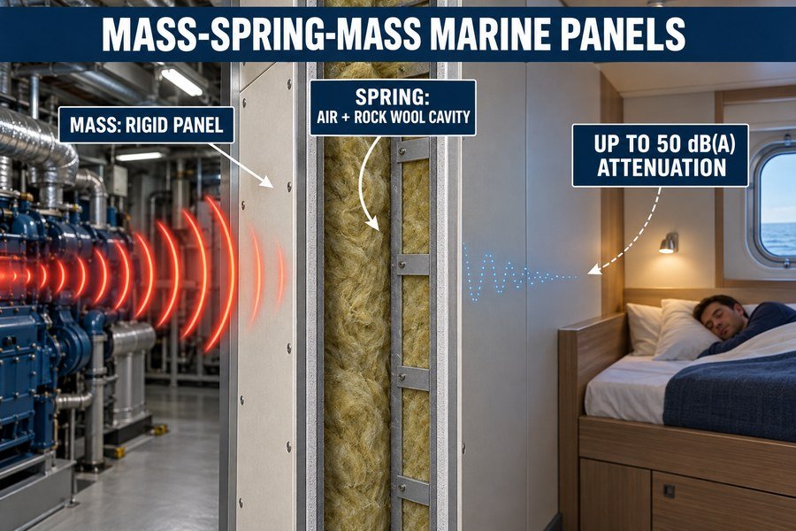
When I worked on a cruise ship project in Europe, we had a huge problem. The shipyard wanted 45 dB noise reduction between cabins, but the weight limits were very strict. That is when I learned the real power of mass-spring-mass design for marine outfitting. Let me show you how it works.
How Does a Mass-Spring-Mass Build-Up Push Marine Interior Panel Insulation Beyond Mass Law?
Adding mass to block sound hits a hard limit. Your ship becomes too heavy. A mass-spring-mass system breaks this barrier using three distinct acoustic principles.
A mass-spring-mass build-up beats the mass law through three principles: decoupling the two facing panels, absorbing sound energy in the spring cavity, and shifting the resonance frequency below 50 Hz. This yields a 10 to 15 dB greater sound reduction than a solid panel of the exact same weight.
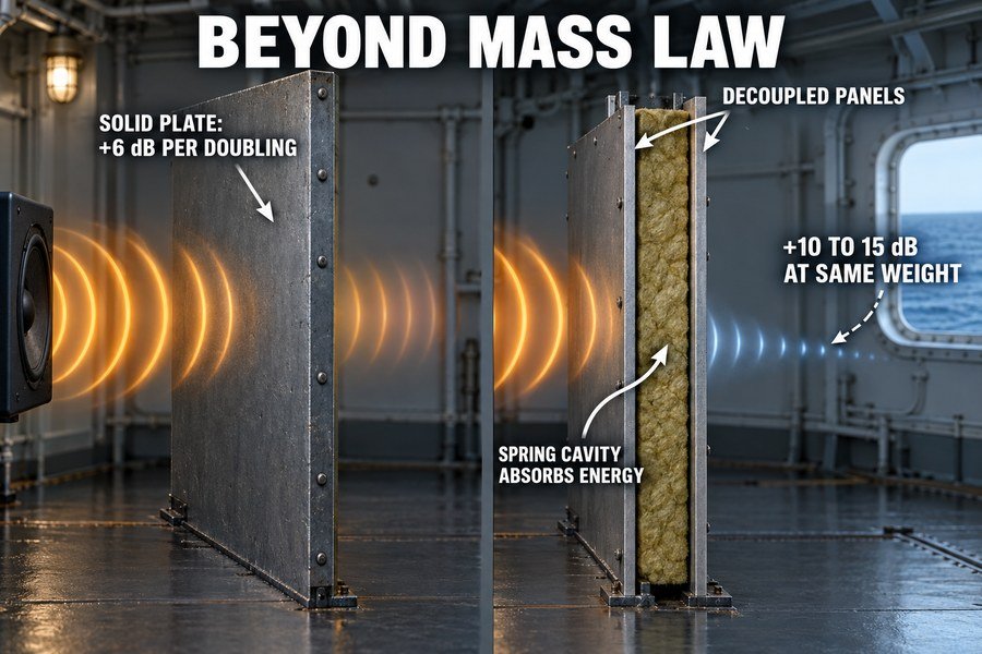
According to the standard acoustic mass law, doubling the weight of a solid bulkhead only gives you a 6 dB increase in sound reduction1. For a marine wall panel needing 45 dB to meet ISO 717-1 standards, you would need steel panels weighing over 40 kg/m². That is too heavy for most ship interior outfitting projects. We use the mass-spring-mass principle to push beyond this limit using three specific methods.
Decoupling the Facing Panels for Better Acoustic Isolation
First, we decouple the two facing panels. In a traditional solid wall, sound vibrations travel straight through the material. Instead of one thick 20mm steel sheet, a mass-spring-mass system uses two 0.6mm galvanized steel skins separated by an empty space. Because the two panels do not touch directly, sound vibrations cannot easily pass from one room to the next. The energy must transfer from the first steel plate, into the air, and then into the second plate. This double transfer loses a massive amount of sound energy.
Absorbing Sound Energy and Shifting Resonance Frequency
Second, we absorb the sound energy in the spring cavity. We put marine-grade rock wool inside the gap. When sound waves pass through the first steel skin, they hit this rock wool core. The dense wool fibers turn the acoustic energy into tiny amounts of heat through friction2. This absorption stops the sound from bouncing around inside the wall.
Third, we shift the resonance frequency below 50 Hz. Every wall has a resonance dip where it naturally lets sound through. By adjusting the gap distance between the plates, we force this dip down to a very low frequency that human ears hardly notice.
| Acoustic Feature | Standard Mass Law Panel | Mass-Spring-Mass Panel |
|---|---|---|
| Material Build | Single 10mm Steel Plate | Two 0.6mm Steel Plates + 50mm Wool |
| Total Weight | Approx. 78 kg/m² | Approx. 18 kg/m² |
| Sound Reduction (Rw) | 40 dB | 45 dB |
| Space Required | 10 mm | 50 mm |
Which Layer Acts as the Spring in a Marine Sandwich Bulkhead?
People often buy expensive facing panels but ignore the core materials. A bad core ruins the soundproofing. The spring layer consists of three specific components working together.
In a marine sandwich bulkhead, the spring layer consists of three elements: the trapped air cavity, the porous mineral wool core (typically 100-150 kg/m³ density), and resilient acoustic dampeners or profiles. Together, they compress and expand to absorb vibrations passing between the two rigid steel or aluminum facing panels.
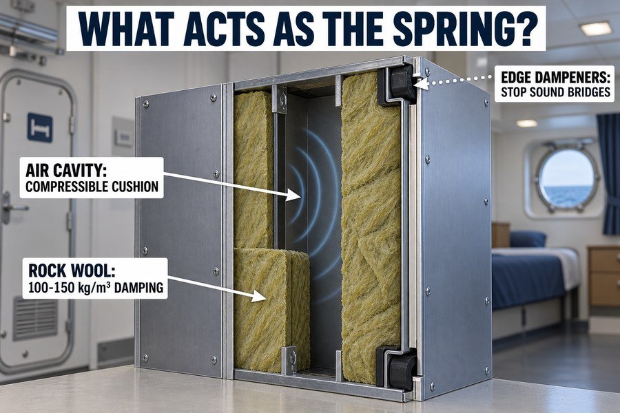
When my clients buy a marine fire door or a marine wall panel, they often ask me what the "spring" actually is. The spring is not a metal metal coil like in a car suspension. It consists of three specific elements: the trapped air cavity, the porous mineral wool core, and the resilient acoustic dampeners.
The Role of the Air Cavity and Mineral Wool Core
Let us start with the trapped air cavity and the mineral wool core. Air itself acts like a spring.3 When the first steel plate vibrates from cabin noise, it physically compresses the air behind it. But air alone is not enough to stop the noise. We must fill this cavity with porous mineral wool. According to data from major marine rock wool manufacturers, a density of 100 to 150 kg/m³ is ideal for marine bulkheads. This specific density stops the air from moving freely. The wool fibers flex slightly and absorb the sound energy, acting as a damped spring.
Using Resilient Acoustic Dampeners to Complete the Spring
The third element is the resilient acoustic dampener. If you just screw two steel panels directly to a rigid metal frame, the metal frame acts like a solid sound bridge. The sound will bypass the air and the wool completely. To fix this, we use rubber dampeners, neoprene strips, or specially bent metal profiles (like Z-profiles or U-channels) at the edges of the panel. These materials act as shock absorbers. When the ship engine vibrates, these dampeners flex and compress. They disconnect the steel faces from the ship's main structure. Without these dampeners, the spring layer fails completely.
| Spring Layer Component | Material Used | Primary Acoustic Function |
|---|---|---|
| Air Cavity | Trapped Air Space (50mm+) | Acts as the primary compressible cushion |
| Mineral Core | Rock Wool (100-150 kg/m³) | Adds damping and turns sound into heat |
| Edge Dampeners | Neoprene Strips / Rubber Grommets | Prevents structural sound bridging at edges |
How Does the Mass-Spring-Mass Resonance Dip Affect Marine Ceiling Insulation?
You install a premium ceiling, but low engine hum still gets through. The resonance dip is the culprit. This dip causes three specific acoustic failures in ships.
The mass-spring-mass resonance dip affects marine ceiling insulation by causing low-frequency sound leakage (typically around 50-100 Hz), amplifying engine vibration transmission, and triggering coincidence effect failures. If the ceiling gap is too small, this resonance dip aligns with ship engine noise, destroying the cabin's acoustic comfort.
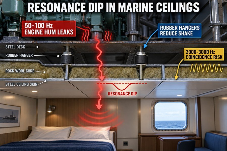
Every mass-spring-mass system has a natural weakness called the resonance dip4. At one specific low frequency, the two mass panels and the spring layer will vibrate together in perfect rhythm. When this happens, the ceiling actually stops blocking sound. This resonance dip affects marine ceiling panels in three very specific ways.
Low-Frequency Sound Leakage and Engine Vibration Transmission
First, it causes low-frequency sound leakage. A typical ship engine generates most of its noise around 50 Hz to 100 Hz5. If your ceiling's resonance dip is also at 80 Hz, the ceiling will let all that heavy engine noise straight into the passenger cabin. According to ISO 717-1 testing standards, you must calculate this dip before installation to ensure you meet the required Ctr (low-frequency traffic/engine noise) adaptation terms.
Second, it amplifies engine vibration transmission. A marine ceiling panel hangs directly from the steel deck above using metal hangers. If the resonance dip matches the natural vibration frequency of the steel deck, the entire ceiling will shake violently. This causes rattling noises and ruins the passenger experience. We solve this by adding rubber vibration isolators to the ceiling hangers.
Preventing Coincidence Effect Failures in Marine Ceilings
Third, it triggers coincidence effect failures. This happens when the speed of the sound wave in the air perfectly matches the bending wave speed in the steel ceiling panel itself. While the main resonance dip happens at low frequencies, this coincidence dip happens at high frequencies (usually around 2000 Hz to 3000 Hz for thin steel). The spring layer must be deep enough, and the wool dense enough, to control both the low-frequency dip and the high-frequency coincidence dip.
| Acoustic Failure Type | Typical Frequency Range | Primary Cause | Solution |
|---|---|---|---|
| Main Resonance Dip | 40 Hz - 100 Hz | Gap between panels is too small | Increase air cavity depth |
| Vibration Transmission | 10 Hz - 50 Hz | Direct contact with ship steel deck | Install rubber ceiling hangers |
| Coincidence Effect | 2000 Hz - 3000 Hz | Steel panel thickness matching sound waves | Add damping layer to steel skin |
How Should Engineers Size a Marine Bulkhead's Spring Layer for a Target Frequency?
Guessing panel thickness leads to failed acoustic tests. You waste money rebuilding cabins. You must size the spring layer using three exact calculation steps.
To size a marine bulkhead's spring layer for a target frequency, engineers follow three steps: identify the lowest target noise frequency (usually engine hum at 50 Hz), calculate the required air cavity depth using the mass-spring resonance formula, and select mineral wool with a flow resistivity of 10-20 kPa·s/m².
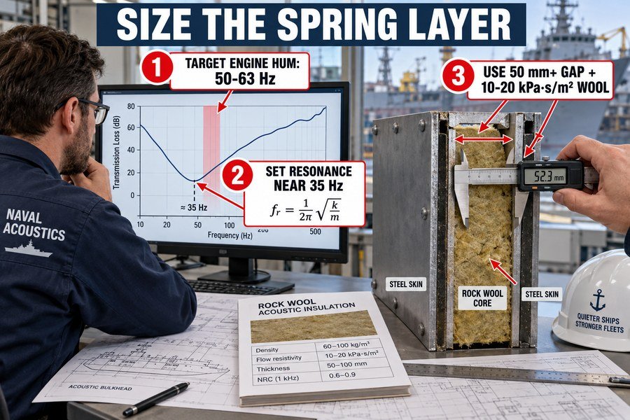
Designing a marine fire door or marine wall panel is not just about fire ratings. You must size the spring layer correctly for sound. If you want to block low-frequency noise in a ship, you cannot just guess the thickness. You must follow three exact steps to get it right.
Identifying the Target Noise Frequency and Calculating Cavity Depth
First, you must identify the target noise frequency. On most commercial vessels, the lowest and most difficult problem frequency comes from the main engines or propellers6. Data from the IMO (International Maritime Organization) shows this noise typically peaks around 50 Hz to 63 Hz7. You must set your target resonance frequency at least half an octave below this noise peak. Usually, we aim for a resonance frequency around 35 Hz.
Second, you calculate the required air cavity depth. The physics formula for the mass-spring resonance frequency (f0) uses the mass of the two steel panels and the distance between them8. If you have two 15 kg/m² steel panels and you need a resonance frequency of 35 Hz, standard acoustic calculations dictate you need an air gap of at least 50mm9. If you shrink the gap to 25mm to save space, the resonance frequency jumps up to 50 Hz. This will directly match the engine noise, and the panel will fail completely.
Selecting the Correct Mineral Wool Flow Resistivity
Third, you select mineral wool with the right airflow resistivity. You cannot just use any standard building insulation. For a 50mm cavity, you need marine-grade rock wool with a specific airflow resistivity of 10 to 20 kPa·s/m². This specific range provides the exact amount of friction needed to damp the sound waves. If the number is too low, sound passes right through.
| Sizing Step | Engineering Action | Target Value / Goal |
|---|---|---|
| Step 1: Identify Noise | Measure ship engine frequencies | Find peak noise (usually 50-63 Hz) |
| Step 2: Calculate Depth | Apply mass-spring resonance formula | Target resonance below 35 Hz (requires 50mm+ gap) |
| Step 3: Select Wool | Check manufacturer acoustic data sheets | 10 to 20 kPa·s/m² airflow resistivity |
Why Does an Overly Stiff Spring Layer Ruin a Marine Accommodation Mass-Spring-Mass Design?
Packing insulation too tightly seems like a good idea. But a stiff wall transmits noise perfectly. A stiff spring layer ruins the design in three ways.
An overly stiff spring layer ruins a marine accommodation mass-spring-mass design by creating structural sound bridging, shifting the resonance dip into human speech frequencies (500-1000 Hz), and eliminating the internal sound absorption capacity. This essentially turns a decoupled double-leaf partition back into a poorly performing single solid wall.
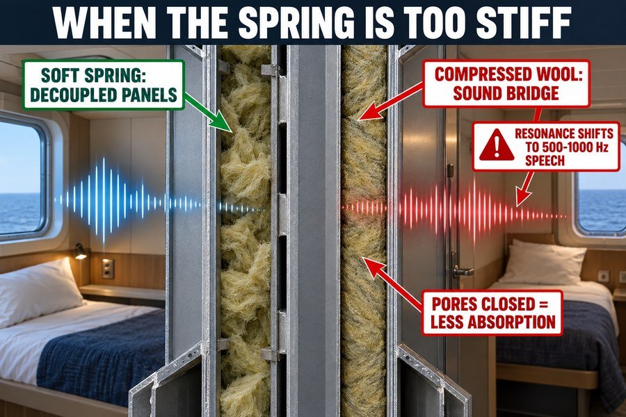
Sometimes a shipyard will try to compress a 100mm thick rock wool slab into a 50mm wall frame to save space. They think more material equals more soundproofing. This is a huge mistake. An overly stiff spring layer ruins the mass-spring-mass effect in three specific ways, destroying the acoustic privacy of the cabin.
Structural Sound Bridging and the Loss of Sound Absorption
First, it creates structural sound bridging. The whole point of the spring layer is to keep the two mass panels decoupled and floating. If you pack the mineral wool too tightly, the wool becomes solid.10 It acts like a wooden block. When sound hits the front panel, the stiff wool physically pushes the back panel. It transmits the sound directly through the wall.
Second, it eliminates the internal sound absorption capacity. Mineral wool works because air and sound waves can enter its porous structure and lose energy through friction.11 If the wool is compressed to a density above 200 kg/m³, the pores close up.12 The sound waves just bounce off it like a brick wall. The spring loses its ability to absorb any acoustic energy.
Shifting the Resonance Dip into Human Speech Frequencies
Third, it shifts the resonance dip into human speech frequencies. A soft spring keeps the resonance dip down around 40 Hz, which is a low rumble. A stiff spring pushes that resonance dip way up to 500 Hz or 1000 Hz.13 According to standard acoustic speech curves, 500 Hz to 1000 Hz is exactly the frequency range of human speech. If the wall's resonance dip is at 1000 Hz, the passenger will hear every single word spoken in the next cabin.
| Acoustic Property | Soft Spring (Correct Design) | Overly Stiff Spring (Incorrect Design) |
|---|---|---|
| Wool Density | 100 - 150 kg/m³ | Over 200 kg/m³ (compressed) |
| Panel Coupling | Decoupled (Vibrations isolated) | Bridged (Vibrations pass directly) |
| Resonance Dip Location | Low frequency (~40 Hz) | Mid frequency (~500 - 1000 Hz) |
| Speech Privacy (STI) | Excellent (Voices blocked) | Poor (Voices clearly heard) |
Conclusion
Using mass-spring-mass design correctly saves weight and blocks noise effectively. By managing the spring layer and decoupling panels, you can secure competitive pricing and premium acoustic comfort for any ship outfitting project.
-
"A Comparative Study of Sound Transmission Loss Provided by ...", https://www.academia.edu/99904089/A_Comparative_Study_of_Sound_Transmission_Loss_Provided_by_Glass_Acrylic_and_Polycarbonate. Acoustic mass-law treatments of homogeneous single-leaf barriers state that, in the mass-controlled frequency region, transmission loss increases by about 6 dB for each doubling of surface mass or frequency. Evidence role: mechanism; source type: education. Supports: According to the standard acoustic mass law, doubling the weight of a solid bulkhead only gives you a 6 dB increase in sound reduction.. Scope note: This relationship is an idealized approximation; real panels can deviate because of stiffness, coincidence effects, panel dimensions, and mounting conditions. ↩
-
"[PDF] ACOUSTIC ABSORPTION OF STRUCTURAL MEMBRANES", https://upcommons.upc.edu/bitstreams/502601a9-62d2-4307-984c-b201c751d240/download. Porous absorber literature describes mineral wool and similar fibrous materials as dissipating sound energy through viscous and thermal losses as air oscillates within the interconnected pores and around fibers. Evidence role: mechanism; source type: paper. Supports: The dense wool fibers turn the acoustic energy into tiny amounts of heat through friction.. Scope note: This supports the general absorption mechanism of rock wool; the actual loss in a specific marine wall depends on density, airflow resistivity, cavity depth, installation, and frequency. ↩
-
"[PDF] Finite Element Analysis of Structural Acoustic Interaction with Air and ...", https://open.clemson.edu/cgi/viewcontent.cgi?article=4042&context=all_theses. A technical acoustics source on double-leaf partitions explains the mass–air–mass mechanism, in which the enclosed air layer between two panels provides the elastic compliance that couples the vibrating leaves. Evidence role: mechanism; source type: education. Supports: The trapped air cavity between steel plates can function acoustically as a spring in a mass–air–mass system.. Scope note: This support is contextual from general architectural or engineering acoustics and may not address marine fire-door or bulkhead constructions specifically. ↩
-
"[PDF] Finite Element Analysis of Structural Acoustic Interaction with Air and ...", https://open.clemson.edu/cgi/viewcontent.cgi?article=4042&context=all_theses. Acoustic transmission-loss models for double-leaf partitions describe a mass–air–mass resonance at which transmission loss is reduced relative to surrounding frequencies; this supports the existence of a low-frequency dip in mass-spring-mass constructions. Evidence role: mechanism; source type: paper. Supports: A mass-spring-mass ceiling can have a low-frequency resonance dip where sound insulation is significantly reduced.. Scope note: The source would support a reduction in insulation, not the absolute claim that sound blocking stops completely; the exact dip frequency depends on panel mass, cavity stiffness, damping, and mounting conditions. ↩
-
"A Vibration Analysis for the Evaluation of Fuel Rail Pressure and Mass Air ...", https://pmc.ncbi.nlm.nih.gov/articles/PMC10934626/. Marine diesel engine and shipboard noise studies report dominant low-frequency tonal components associated with engine rotation, firing orders, and machinery vibration, often in the tens to low hundreds of hertz; this contextualizes the stated 50–100 Hz range for engine-related noise. Evidence role: statistic; source type: paper. Supports: A typical ship engine can generate substantial noise in the 50 Hz to 100 Hz low-frequency band.. Scope note: The dominant frequencies vary with engine speed, number of cylinders, propulsion arrangement, mounting, and measurement location, so the range should be treated as typical rather than universal. ↩
-
"[PDF] Underwater Sound Characteristics of a Ship with Controllable Pitch ...", https://dspace.mit.edu/bitstream/handle/1721.1/141117/jmse-10-00328-v2.pdf. A naval acoustics or IMO-linked source can support that propulsion machinery and propellers are major contributors to low-frequency shipboard noise; this establishes the likely source category rather than proving the exact frequency peak for every vessel. Evidence role: general_support; source type: institution. Supports: On most commercial vessels, the lowest and most difficult problem frequency comes from the main engines or propellers.. Scope note: Noise sources vary by vessel type, operating condition, engine speed, mounting, and compartment location. ↩
-
"Large Vessel Activity and Low-Frequency Underwater ...", https://repository.library.noaa.gov/view/noaa/40091/noaa_40091_DS1.pdf. A ship-noise measurement study or institutional guidance can document that propulsion-related shipboard noise is often prominent in low-frequency octave or one-third-octave bands such as 50–63 Hz; this would support the frequency range as a common design reference, not a universal IMO value. Evidence role: statistic; source type: paper. Supports: Data from the IMO shows this noise typically peaks around 50 Hz to 63 Hz.. Scope note: The cited source may report measured examples or frequency-band trends rather than a universal peak for all commercial vessels. ↩
-
"Airborne sound insulation performance of lightweight double ...", https://pmc.ncbi.nlm.nih.gov/articles/PMC11666719/. An architectural-acoustics textbook, university note, or peer-reviewed paper can support the mass-air-mass resonance model, in which panel surface masses and cavity depth determine the resonance frequency of double-leaf partitions; this supports the governing mechanism rather than validating the article’s specific design numbers. Evidence role: mechanism; source type: education. Supports: The physics formula for the mass-spring resonance frequency uses the mass of the two steel panels and the distance between them.. Scope note: Ideal mass-air-mass formulas assume simplified panels and cavities and may not include structural bridges, seals, frames, damping layers, or marine installation details. ↩
-
"Airborne sound insulation performance of lightweight double ...", https://pmc.ncbi.nlm.nih.gov/articles/PMC11666719/. A recognized acoustics calculation reference can be used to verify the order-of-magnitude air-cavity depth implied by the mass-air-mass resonance formula for two 15 kg/m² leaves targeting about 35 Hz; this supports the calculation method and approximate result, not a certified marine fire-door design. Evidence role: mechanism; source type: education. Supports: If you have two 15 kg/m² steel panels and need a resonance frequency of 35 Hz, standard acoustic calculations dictate an air gap of at least 50 mm.. Scope note: The result depends on the exact formula convention, panel masses, cavity assumptions, stiffness of connections, and whether porous fill changes the effective damping or resonance behavior. ↩
-
"Airborne sound insulation performance of lightweight double ...", https://pmc.ncbi.nlm.nih.gov/articles/PMC11666719/. Building-acoustics literature on double-leaf partitions explains that rigid or highly stiff connections across the cavity can increase mechanical coupling between leaves, supporting the claim that over-compressed cavity fill can undermine decoupling. Evidence role: mechanism; source type: paper. Supports: Over-compressing mineral wool in a double-panel wall can create a structural sound bridge that mechanically couples the two panels.. Scope note: The source may support the general coupling mechanism rather than testing this exact rock-wool thickness and ship-cabin wall assembly. ↩
-
"Absorption (acoustics)", https://en.wikipedia.org/wiki/Absorption_(acoustics). Acoustics references on porous absorbers describe sound absorption as viscous and thermal losses that occur as air motion passes through interconnected pores, supporting the mechanism stated for mineral wool. Evidence role: mechanism; source type: education. Supports: Mineral wool absorbs sound because its porous fibrous structure converts acoustic energy into heat through viscous and thermal losses.. Scope note: This supports the general absorption mechanism of porous fibrous materials; the exact absorption depends on product thickness, flow resistivity, mounting, and frequency. ↩
-
"Acoustic Performance of Sound Absorbing Materials ... - PMC", https://pmc.ncbi.nlm.nih.gov/articles/PMC9105389/. Studies of fibrous acoustic materials report that increasing density or compression changes porosity and airflow resistivity, which can reduce absorption when the material becomes too resistive to air motion. Evidence role: mechanism; source type: paper. Supports: Excessive compression or high density in fibrous insulation can reduce acoustic performance by altering porosity and airflow resistivity.. Scope note: A cited source may not validate 200 kg/m³ as a universal cutoff; that threshold should be treated as product- and frequency-dependent unless supported by manufacturer-independent test data. ↩
-
"Airborne sound insulation performance of lightweight double ...", https://pmc.ncbi.nlm.nih.gov/articles/PMC11666719/. Mass-spring-mass partition theory relates the resonance frequency to the dynamic stiffness of the cavity spring and the masses of the panels, supporting the claim that a stiffer cavity layer raises the resonance frequency. Evidence role: mechanism; source type: paper. Supports: Increasing the stiffness of the spring layer in a mass-spring-mass wall system raises the resonance frequency and can move the insulation dip upward.. Scope note: The source may establish the direction of the frequency shift; the specific 500–1000 Hz values require calculations or measurements for the stated wall masses, cavity depth, and insulation stiffness. ↩