
Passenger complaints about cabin noise can quickly ruin a ship's reputation. Bad ceiling connections often let sound bypass expensive panels. I will show you how structural links change ceiling acoustics.
Structural connections impact marine ceiling panel acoustics by introducing two main sound transmission paths: direct mechanical vibration through rigid suspension hangers, and flanking noise through perimeter profiles. Poorly isolated connections can reduce a ceiling's Sound Reduction Index (Rw) by 5 to 10 decibels compared to laboratory tests.
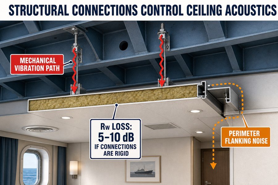
Let us break down the specific ways these connections affect noise and look at how we can fix them during the ship outfitting process.
How Does Deck-to-Deck Marine Ceiling Panel Noise Differ from Wall Noise?
Hearing footsteps from the deck above is a common headache for shipbuilders. Wall noise is mostly airborne, but ceiling noise brings different, harder-to-solve problems. Here is the exact difference.
Deck-to-deck ceiling noise differs from wall noise by involving two distinct transmission types: structure-borne impact noise (like footsteps transferring 50-70 dB of low-frequency energy directly through the steel deck) and airborne noise (like voices). Wall noise is almost exclusively airborne, making ceiling acoustic treatments significantly more complex.
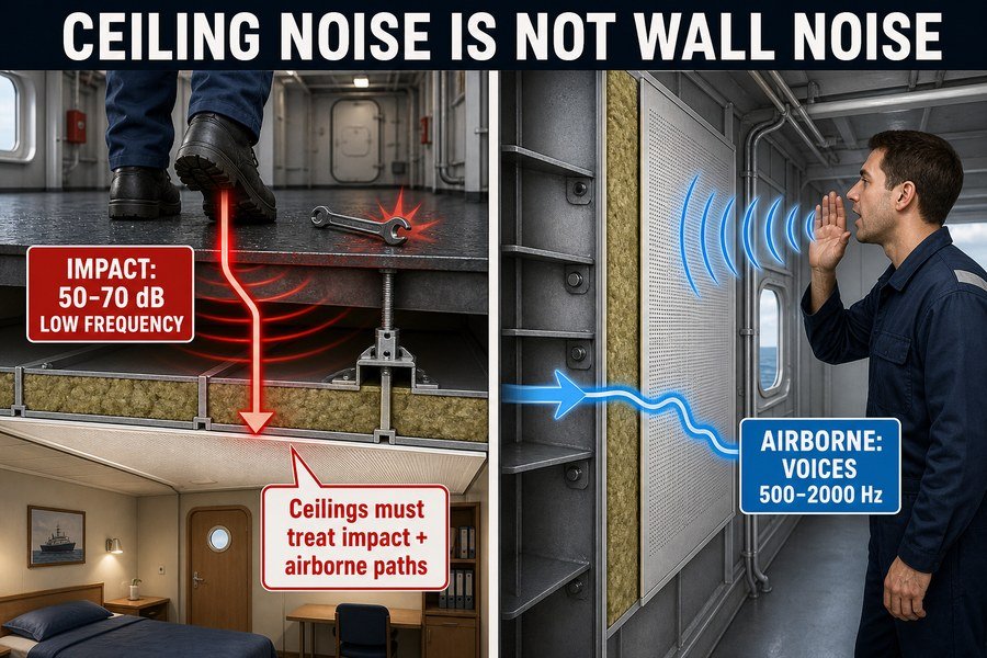
I often see shipyard buyers confuse wall noise with ceiling noise. Let me explain this clearly so you can buy the right materials. The first type of noise in a ceiling system is structure-borne impact noise. When a crew member drops a heavy tool or walks with heavy boots on the steel deck above, the impact sends shockwaves directly into the metal. This physical hit generates strong vibration. According to standard ISO 717-2 acoustic testing, this type of impact noise easily transfers 50 to 70 decibels (dB)1 of low-frequency energy straight down into the cabin below. Because this low-frequency sound is mostly under 250 Hertz (Hz), it travels very easily through solid steel structures2. You cannot block this with just thin foam.
Structure-Borne Impact Noise in Marine Ceilings
Structure-borne impact noise is the biggest challenge in ceiling design. The metal deck acts like a drum. When you strike it, the whole structure shakes. To stop this, you need heavy mass and specialized vibration isolators. If you ignore the impact noise, the passengers below will hear every footstep, which causes many complaints on luxury vessels.
Airborne Noise Transmission Through Ship Bulkheads
The second type is airborne noise. Think of people talking loudly, a radio playing, or television sounds in the room next door. This sound travels through the air, hits the wall or ceiling panel, and tries to pass through. Standard B-15 marine wall panels usually block 30 to 35 dB of airborne sound3. This is much easier to manage than impact noise. Airborne sound is mostly in the mid-to-high frequency range, usually between 500 Hz and 2000 Hz. Standard rockwool insulation can block this easily. Wall noise is almost 100% airborne, which is why a simple sandwich panel works well for bulkheads. But because ceilings face both impact and airborne noise, they need a completely different design approach to meet the IMO Resolution A.468(XII) cabin noise limit of 60 dB(A).
| Noise Type | Primary Source | Frequency Range | Energy Transfer Method | Required Acoustic Treatment |
|---|---|---|---|---|
| Structure-Borne Impact | Footsteps, dropped tools, engines | Low (20 - 250 Hz) | Direct physical vibration through steel | Rubber isolators, heavy mass barriers |
| Airborne | Human voices, TV, music | Mid to High (500 - 2000 Hz) | Sound waves traveling through air | Porous rockwool, sealed joints |
How Do Suspension Systems Create Sound Bridges in Marine Ceiling Panels?
You buy a 45 dB rated ceiling panel, but the cabin still sounds loud. Rigid suspension hangers act as secret highways for noise. Here is how they fail.
Suspension systems create sound bridges in marine ceiling panels through three mechanisms: rigid steel-to-steel hanger contacts that transfer vibration, uninsulated perimeter edge trims that leak high-frequency sounds, and improperly tensioned grid systems that resonate at specific engine frequencies. These bridges bypass the panel's internal insulation completely.
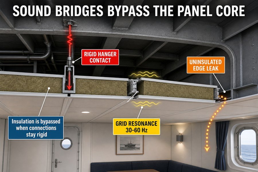
A sound bridge is exactly what it sounds like. It is a physical bridge that allows sound to bypass your expensive insulation. In my time working with ship interior decoration companies, I have seen many good panels fail because of bad suspension systems.
Rigid Steel-to-Steel Hanger Contacts in Ceiling Grids
The first mechanism is rigid steel-to-steel hanger contacts. When you hang a ceiling panel, you use metal rods or brackets to connect the panel grid to the ship's steel deck overhead. Metal is an excellent conductor of sound. In fact, sound travels at about 5000 meters per second through solid steel4. When the ship's engine runs, the vibration travels from the hull, into the deck, down the steel hanger, and directly into the ceiling panel. The ceiling panel then shakes and acts like a giant speaker inside the cabin.
Uninsulated Perimeter Edge Trims as Acoustic Leaks
The second mechanism involves uninsulated perimeter edge trims. This is the metal track where the ceiling meets the wall panel. Installers often leave small gaps here to make the ceiling panels easier to slide into place. However, sound acts like water. It will find the easiest path to escape. These small gaps at the edges allow high-frequency airborne sounds to leak straight into the cabin. Even a 1% gap can reduce your ceiling's acoustic performance by up to 10 dB5.
Improperly Tensioned Grid Systems and Resonance
The third mechanism is an improperly tensioned grid system. Ship engines create constant, specific vibrations, usually between 30 Hz and 60 Hz6. If the metal grid holding the ceiling panels is loose, it will catch these vibrations and start to resonate. Resonance means the grid shakes violently at the same frequency as the engine. This creates a loud buzzing or humming noise inside the cabin. To solve this, workers must install the grid tightly and use anti-vibration clips.
| Sound Bridge Mechanism | Location | Acoustic Penalty | Recommended Solution |
|---|---|---|---|
| Rigid Steel Hangers | Deck-to-grid connection | 5 to 8 dB loss | Install rubber or spring vibration isolators |
| Perimeter Edge Trims | Ceiling-to-wall joint | 3 to 10 dB loss | Fill gaps with acoustic sealant and foam tape |
| Grid Resonance | Main suspension rails | Hum/Buzz (30-60 Hz) | Tighten grid and apply damping mass layers |
Why Does Rockwool Overlay Improve Low-Frequency Marine Ceiling Panel STL?
Low-frequency engine rumble easily penetrates standard metal ceilings. The noise makes cabins miserable for crew and passengers. Adding a rockwool overlay solves this heavy vibration issue.
Rockwool overlay improves low-frequency marine ceiling panel Sound Transmission Loss (STL) through two main physical actions: adding essential mass that resists low-frequency sound wave penetration, and providing porous sound absorption that dissipates acoustic energy into heat. A 50mm, 100kg/m3 overlay can boost STL by 3-5 dB at 125 Hz.
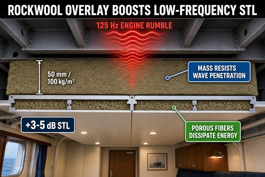
Engine rumble is the hardest sound to stop on a ship. Low-frequency sound waves are very long and carry a lot of energy.7 A standard thin metal ceiling panel simply cannot stop them. This is why we add a heavy rockwool overlay on top of the ceiling panels.
Adding Essential Mass to Resist Low-Frequency Sound
The first physical action is adding essential mass. In acoustics, we use the "Mass Law8." This law states that to stop heavy, low-frequency sound, you need heavy, dense materials. A standard steel ceiling panel is too light. When we add a layer of rockwool that is 50mm thick with a density of 100 kilograms per cubic meter (kg/m3), we add about 5 kilograms of mass to every square meter of the ceiling. This extra weight makes it much harder for the low-frequency sound waves to push through the panel. According to standard acoustic test data, this extra mass will improve the Sound Transmission Loss (STL) by 3 to 5 decibels at the difficult 125 Hz frequency range.
Porous Sound Absorption Dissipating Acoustic Energy
The second physical action is porous sound absorption. Rockwool is made of millions of tiny stone fibers packed together. When airborne sound waves enter the rockwool, the sound pushes the air back and forth against these rough fibers. This creates physical friction. The friction turns the acoustic sound energy into a tiny amount of heat energy.9 The sound is literally absorbed and destroyed inside the rockwool. Without this porous layer, sound waves would bounce continuously between the steel deck and the metal ceiling panel, building up pressure and making the cabin louder. By using a 100kg/m3 rockwool overlay, we get both the mass needed to block the sound and the porous fibers needed to absorb the sound that gets trapped above the ceiling.
| Rockwool Overlay Specification | Physical Action Provided | Acoustic Benefit | Typical Cost Impact (USD per m2) |
|---|---|---|---|
| 30mm thick, 60kg/m3 density | Basic absorption | Stops high-frequency echo | $3.00 - $5.00 |
| 50mm thick, 100kg/m3 density | Mass addition + heavy absorption | +3 to 5 dB STL at 125 Hz | $8.00 - $12.00 |
| 100mm thick, 120kg/m3 density | Extreme mass barrier | +6 to 8 dB STL at 125 Hz | $15.00 - $22.00 |
How Does the Plenum Air Gap Affect Marine Ceiling Panel Rw?
The empty space between the steel deck and the decorative ceiling panel holds a secret. If you ignore it, cabin acoustics suffer greatly. This air gap changes everything.
The plenum air gap affects marine ceiling panel Rw (Sound Reduction Index) by acting as an acoustic spring in a mass-spring-mass system. A deeper gap (over 100mm) improves low-frequency insulation, while a shallow gap (under 50mm) creates a stiff air cushion that reduces overall Rw by causing cavity resonance.
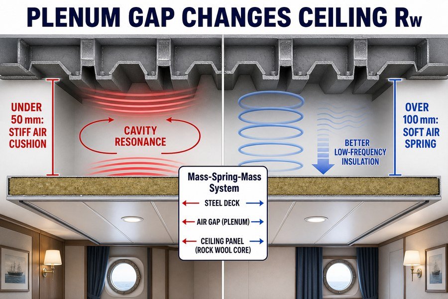
When you install a marine ceiling, you must leave a gap between the steel deck above and the ceiling panel below. We call this empty space the plenum. Many buyers do not realize that the size of this air gap changes the acoustic rating of the panel.
Deeper Air Gaps Enhancing Low-Frequency Insulation
In acoustic engineering, a ceiling system acts as a "mass-spring-mass" system10. The steel deck is the first heavy mass. The ceiling panel is the second mass. The air inside the plenum gap acts like a physical spring connecting them. The depth of this gap changes how the spring behaves. A deeper gap, usually over 100 millimeters (mm), creates a very soft, flexible air spring.11 When low-frequency engine noise hits the steel deck, the soft air spring absorbs the energy. It does not transfer the energy to the ceiling panel below. This deep gap greatly improves the low-frequency insulation and raises the overall Sound Reduction Index (Rw) of the cabin.
Shallow Air Gaps Causing Cavity Resonance Issues
However, a shallow gap causes major problems. If the gap is under 50mm, the air inside gets trapped tightly. It becomes a very stiff spring. When vibration hits the deck, this stiff air cushion pushes directly against the ceiling panel. Even worse, shallow gaps create cavity resonance12. This means the sound bounces rapidly between the deck and the ceiling, amplifying specific low frequencies. This stiff spring effect can reduce your overall Rw rating by 2 to 4 dB13. Because shipbuilders always want to save space and make ceilings higher, they often force installers to use shallow 30mm gaps. As a marine outfitting specialist, I always tell my clients to fight for at least a 100mm gap if they want their acoustic ceiling panels to perform properly.
| Plenum Air Gap Depth | Spring Characteristic | Acoustic Impact on System Rw | Risk of Cavity Resonance |
|---|---|---|---|
| Under 50mm | Very Stiff | Decreases Rw by 2 to 4 dB | Very High |
| 50mm to 100mm | Moderate | Neutral (Lab baseline) | Medium |
| Over 100mm | Soft and Flexible | Increases Rw by 2 to 5 dB | Low |
Why Is Vibration Isolation Critical for Marine Ceiling Panel Acoustics?
You can use the thickest insulation available, but vibrations will still shake the ceiling. This creates noise directly inside the cabin. Vibration isolation stops this completely.
Vibration isolation is critical for marine ceiling panel acoustics because it interrupts the direct mechanical path from the ship's steel structure to the ceiling surface. Without rubber or silicone isolators, low-frequency engine vibrations (20-100 Hz) bypass the panel's acoustic core, radiating as secondary airborne noise directly into the passenger cabin.
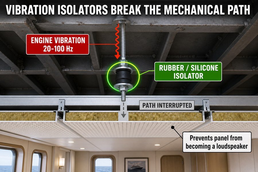
Ship engines and propellers create massive amounts of physical vibration. This energy travels through the steel hull and into the decks.14 If you bolt a ceiling panel directly to the steel deck, you are giving that vibration a free ride into the cabin.
Interrupting the Direct Mechanical Transmission Path
This is why interrupting the direct mechanical transmission path is so critical. We use vibration isolators, which are small mounts made of rubber or silicone. When you hang the ceiling grid, you install these isolators between the steel deck and the hanger rods. The rubber acts as a shock absorber.15 When the heavy vibration travels down the steel, it hits the soft rubber and stops. The rubber bends and flexes, which breaks the physical bridge. Without these isolators, sound travels perfectly through rigid metal-to-metal connections. The cost of a rubber isolator is small, usually between $2 and $5 each, but skipping them will ruin a $100,000 cabin outfitting job.
Preventing Secondary Airborne Noise Radiation
If you do not interrupt this path, a terrible thing happens. The low-frequency engine vibrations, usually between 20 Hz and 100 Hz16, will bypass the ceiling panel's expensive acoustic core completely. The physical metal face of the ceiling panel will begin to shake rapidly. When a large metal panel shakes, it pushes the air inside the cabin. It literally becomes a giant loudspeaker.17 We call this secondary airborne noise radiation. The panel itself generates the noise inside the room. You can have the best rockwool in the world inside the panel, but if the metal skin is vibrating, the cabin will be incredibly loud. Vibration isolators prevent the panel from becoming a speaker.
| Isolator Material Type | Frequency Target Range | Best Application | Estimated Unit Cost (USD) |
|---|---|---|---|
| Standard Neoprene Rubber | 40 Hz and above | General cabin areas, standard engine vibration | $2.00 - $4.00 |
| High-Deflection Silicone | 20 Hz to 40 Hz | Luxury cabins, close to main engine rooms | $5.00 - $9.00 |
| Steel Spring Mounts | 10 Hz to 20 Hz | Cinema rooms, heavy machinery areas | $12.00 - $25.00 |
Why Do Installed Marine Ceiling Panels Often Underperform Their Lab Rw?
Buyers often ask me why a 45 dB lab-tested ceiling only blocks 35 dB on their ship. Real-world shipyard installation is messy. Here are the three main reasons.
Installed marine ceiling panels underperform their lab Rw due to three real-world factors: flanking transmission through connecting walls and floors, acoustic leaks from unsealed penetrations for lights and HVAC vents, and rigid installation errors where workers omit vibration isolators. These shipyard realities can reduce the effective Rw by 5-15 dB.
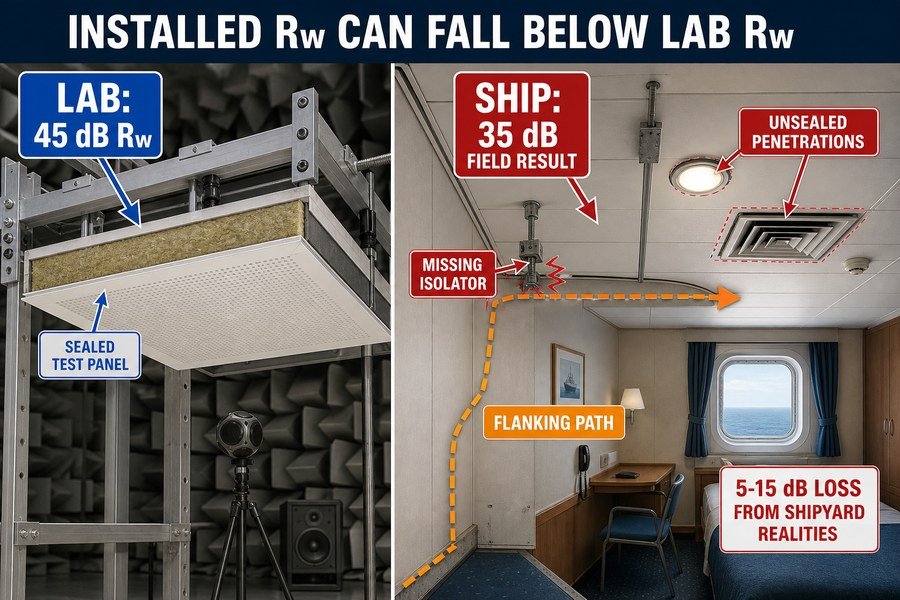
This is the most common frustration for procurement officers. You spend good money on a certified marine ceiling panel with a high lab rating, but the final result on the ship is terrible. Lab conditions are perfect. The ship environment is not.
Flanking Transmission Through Connecting Marine Walls
The first major factor is flanking transmission. When an acoustic laboratory tests a panel, they put it in an isolated concrete frame. Sound can only go through the panel itself. On a real ship, sound takes shortcuts. Even if your ceiling blocks 45 dB of noise, the sound will travel down the steel walls, through the ventilation ducts, and through the deck floor. This indirect travel is called flanking. If the walls and floors are not insulated perfectly, flanking noise will enter the cabin, making it seem like the ceiling failed. Flanking alone can drop the overall room acoustic performance by 3 to 5 dB.18
Acoustic Leaks from Unsealed Ceiling Penetrations
The second factor involves acoustic leaks from unsealed penetrations. In the lab, the ceiling panel is a solid, unbroken square. On a ship, workers must cut large holes in the ceiling for LED lights, fire sprinklers, and HVAC air vents. Every hole you cut destroys the acoustic barrier. If workers do not seal the gaps around these lights with acoustic putty or fire-rated silicone, sound pours through the holes. Basic acoustic principles dictate that leaving just a 1% open area in a ceiling will reduce a 40 dB panel down to 30 dB19.
Rigid Installation Errors by Shipyard Workers
The third factor is rigid installation errors. Shipyard schedules are very tight. Workers are always rushing to finish the interior decoration. To save time, workers will often throw away the flexible rubber vibration isolators and screw the ceiling grids directly into the steel deck. Or, they will use incorrect, hard metal screws instead of flexible mounts. This immediately creates a rigid sound bridge. It completely ruins the isolation design. A rigid installation error will easily cause a 5 to 10 dB loss in field performance.20 Proper supervision during installation is the only way to prevent this waste of money.
| Real-World Degradation Factor | Cause on the Shipyard | Potential Rw Loss | Prevention Method |
|---|---|---|---|
| Flanking Transmission | Sound travels through connected walls/floors | 3 to 5 dB | Use continuous acoustic floating floors and insulated wall joints |
| Unsealed Penetrations | Cutting holes for lights and HVAC | 5 to 10 dB | Use acoustic putty pads behind light fixtures |
| Rigid Installation Errors | Workers rushing, skipping rubber mounts | 5 to 10 dB | Strict quality control checks before closing the ceiling |
Conclusion
Proper structural connections are vital for marine ceiling acoustics. By controlling impact noise, sound bridges, air gaps, and vibration paths, you ensure field performance matches laboratory ratings for quieter cabins.
-
"[PDF] SOUND STUDY - USDA Rural Development", https://www.rd.usda.gov/media/file/download/usda-rd-attachment-14-sound-study-09082025.pdf. A measurement study or standardized test report for ship deck-ceiling assemblies can support the stated order of magnitude for impact sound levels transmitted to receiving rooms under standardized tapping or impact excitation. Evidence role: statistic; source type: paper. Supports: Impact noise through a steel deck-ceiling system can transmit roughly 50 to 70 dB into the cabin below.. Scope note: The exact dB range is construction-dependent and ISO 717-2 defines rating procedures rather than guaranteeing a universal transmission level for all marine ceilings. ↩
-
"LOW-FREQUENCY NOISE REDUCTION OF ...", https://ntrs.nasa.gov/api/citations/19660027853/downloads/19660027853.pdf. Acoustics literature on structure-borne sound explains that low-frequency vibration in plates and beams is difficult to attenuate because long wavelengths couple efficiently through stiff structural members such as steel decks. Evidence role: mechanism; source type: education. Supports: Low-frequency structure-borne sound below about 250 Hz can travel efficiently through steel structures.. Scope note: The source would support the physical mechanism generally; actual transmission depends on structural continuity, damping, joints, and isolation design. ↩
-
"In Which Ship Spaces Are Marine Wall Panels Commonly used?", https://magellanmarinetech.com/in-which-ship-spaces-are-marine-wall-panels-commonly-used/. An accredited acoustic test report or classification-society document for a B-15 bulkhead assembly can document an airborne sound reduction index in the low-30 dB range for a specific tested construction. Evidence role: statistic; source type: institution. Supports: Typical B-15 marine wall panel assemblies may provide about 30 to 35 dB of airborne sound reduction.. Scope note: B-15 is primarily a fire-class designation, not an acoustic rating; the cited value should be treated as assembly-specific rather than a universal property of all B-15 panels. ↩
-
"Speed of sound - Wikipedia", https://en.wikipedia.org/wiki/Speed_of_sound. A materials acoustics reference should support that longitudinal sound speed in steel is approximately 5,000 m/s, establishing why steel members can efficiently transmit vibration. Evidence role: statistic; source type: encyclopedia. Supports: Sound travels at about 5000 meters per second through solid steel.. Scope note: The exact velocity varies with steel alloy, temperature, and whether longitudinal or shear wave speed is being reported. ↩
-
"Sound Transmission Loss Research Papers - Academia.edu", https://www.academia.edu/Documents/in/Sound_Transmission_Loss. An architectural acoustics source should support that small unsealed openings can disproportionately reduce the sound insulation of a partition or ceiling, with examples showing losses on the order of several to about 10 dB. Evidence role: statistic; source type: research. Supports: A very small unsealed gap can substantially reduce a ceiling assembly’s acoustic performance, potentially by up to about 10 dB.. Scope note: Evidence may be based on walls, partitions, or laboratory models rather than ship ceiling-edge trims specifically, so it would contextualize rather than directly prove the exact 1%/10 dB figure for this assembly. ↩
-
"Vibration Diagnostics Methods of Marine Diesel Engines ...", https://publications.sto.nato.int/publications/STO%20Meeting%20Proceedings/STO-MP-AVT-306/MP-AVT-306-09.pdf. A ship noise-and-vibration reference should support that marine propulsion and auxiliary machinery commonly generate low-frequency vibration components in the tens of hertz, including frequencies around 30–60 Hz. Evidence role: general_support; source type: paper. Supports: Ship engines commonly produce low-frequency vibration components around 30–60 Hz.. Scope note: The frequency range is equipment- and speed-dependent; a source may support this as a common range rather than a universal property of all ship engines. ↩
-
"Progress of low-frequency sound absorption research utilizing ... - PMC", https://pmc.ncbi.nlm.nih.gov/articles/PMC9044041/. Acoustics references describe wavelength as inversely proportional to frequency and note that low-frequency noise is generally more difficult to attenuate with barriers and lightweight partitions than higher-frequency sound. Evidence role: mechanism; source type: education. Supports: Low-frequency engine noise is difficult to stop because low-frequency sound has long wavelengths and is less readily attenuated by lightweight barriers.. Scope note: This supports the physical rationale but does not by itself quantify performance for a specific ship ceiling assembly. ↩
-
"[PDF] 9. ACOUSTIC ANALYSIS", https://www.engr.psu.edu/ae/thesis/portfolios/2007/PBM119/Final%20Stuff/Acoustics%20Analysis.pdf. Standard building-acoustics treatments of the mass law state that, away from resonance and coincidence regions, sound transmission loss increases with surface mass and frequency, commonly by about 6 dB for each doubling of surface density or frequency. Evidence role: definition; source type: education. Supports: The acoustic mass law is the principle that heavier surface mass generally improves airborne sound transmission loss.. Scope note: The mass law is an idealized model and may not predict exact transmission loss for framed, marine, or multilayer ceiling systems. ↩
-
"Acoustic Absorption in Porous Materials", https://ntrs.nasa.gov/api/citations/20110011143/downloads/20110011143.pdf. Acoustics texts on porous absorbers explain that sound energy is dissipated through viscous and thermal losses as oscillating air moves through interconnected pores or fibrous structures, converting part of the acoustic energy into heat. Evidence role: mechanism; source type: education. Supports: Porous fibrous absorbers such as rockwool dissipate acoustic energy through frictional and thermal losses that convert sound energy into heat.. Scope note: This supports the absorption mechanism of fibrous materials generally, not the exact absorption coefficient of the specified rockwool product. ↩
-
"[PDF] The finite layer method for modelling the sound transmission ...", https://upcommons.upc.edu/bitstreams/6ce7ff3e-10c0-4bbc-baa9-c0aea47a9c5a/download. A building-acoustics or noise-control reference describes double-panel constructions as mass–air–mass systems, where the two panels act as masses and the intervening air cavity provides the spring coupling. Evidence role: mechanism; source type: paper. Supports: A ceiling with a steel deck, an air gap, and a ceiling panel can be modeled acoustically as a mass-spring-mass system.. Scope note: The source will likely discuss double-leaf walls or generic panel systems rather than marine ceiling assemblies specifically. ↩
-
"[PDF] Investigation of transmission loss through double wall structures with ...", https://ir.library.louisville.edu/cgi/viewcontent.cgi?referer=&httpsredir=1&article=2758&context=etd. A neutral acoustics source explains that the stiffness of the trapped air layer in a double-panel system decreases as cavity depth increases, lowering the mass–air–mass resonance frequency and changing low-frequency transmission behavior. Evidence role: mechanism; source type: paper. Supports: Increasing the plenum depth makes the air spring softer in a double-panel acoustic system.. Scope note: The 100 mm threshold may be an engineering rule of thumb; the exact value depends on panel mass, mounting stiffness, absorption in the cavity, and construction details. ↩
-
"[PDF] Finite Element Analysis of Structural Acoustic Interaction with Air and ...", https://open.clemson.edu/cgi/viewcontent.cgi?article=4042&context=all_theses. A reference on enclosed air cavities or double-leaf partitions notes that small cavities can produce resonance effects that increase sound transmission at particular frequencies. Evidence role: mechanism; source type: education. Supports: Shallow air gaps in ceiling or double-panel assemblies can cause cavity resonance that affects sound transmission at specific frequencies.. Scope note: The source may establish the general resonance mechanism rather than proving the magnitude of the effect in marine ceiling plenums. ↩
-
"Airborne sound insulation performance of lightweight double ...", https://pmc.ncbi.nlm.nih.gov/articles/PMC11666719/. A laboratory or standards-based acoustics study comparing otherwise similar double-panel assemblies with different cavity depths can document that changes in cavity spacing alter weighted sound reduction indices by several decibels. Evidence role: statistic; source type: paper. Supports: Very shallow plenum gaps can reduce the weighted sound reduction performance of a ceiling or double-panel assembly by several decibels.. Scope note: The cited data may come from building partitions or laboratory specimens rather than marine ceiling panels, so it should be used as comparative evidence rather than a universal performance guarantee. ↩
-
"[PDF] Discussion Paper Noise", http://maritime.lamar.edu/joomla2025/index.php/ergonomics?download=66:ergonomic-discussion-paper-noise. A marine acoustics or naval engineering source can document that machinery and propeller excitation is transmitted as structure-borne vibration through connected hull and deck structures, supporting the physical transmission pathway described here; it may not quantify the magnitude for this specific ship layout. Evidence role: mechanism; source type: paper. Supports: Ship-engine and propeller vibration can propagate through the steel hull structure and into decks.. Scope note: Contextual support only unless the source studies the same vessel type and deck construction. ↩
-
"[PDF] Barry-isolators-selection-guide.pdf", https://wp.optics.arizona.edu/optomech/wp-content/uploads/sites/53/2016/08/Barry-isolators-selection-guide.pdf. A vibration-isolation reference can explain that elastomeric mounts reduce transmitted vibration by adding compliance and damping between rigidly connected structures, supporting the description of rubber mounts as shock-absorbing elements; such sources generally describe attenuation rather than complete stoppage of vibration. Evidence role: mechanism; source type: education. Supports: Rubber or elastomeric isolators reduce mechanical vibration transmission by flexing and damping motion between connected components.. Scope note: Supports reduction of vibration transmission, not the absolute claim that vibration 'stops.' ↩
-
"[PDF] Vessel-Generated Underwater Radiated Noise Comparison Study ...", https://www.maritime.dot.gov/sites/marad.dot.gov/files/2024-11/NCE%20REPORT%202024-079%20MARAD%20Vessel-Generated%20Underwater%20Radiated%20Noise%20Comparison%20Study%20%28Tugs%29%20Rev%200.pdf. A ship-noise or marine-vibration study can provide measured spectra showing that significant machinery-related vibration and noise components often occur in low-frequency bands, including portions of the 20–100 Hz range; the exact dominant frequencies vary with engine speed, propeller blade rate, mounting, and vessel type. Evidence role: statistic; source type: paper. Supports: Low-frequency engine or machinery vibrations in ships commonly include energy in the 20 Hz to 100 Hz range.. Scope note: Frequency ranges are vessel- and operating-condition dependent, so the source may support the range as typical rather than universal. ↩
-
"[PDF] on the radiation of sound from baffled finite panels", https://ntrs.nasa.gov/api/citations/19770003383/downloads/19770003383.pdf. An acoustics reference can show that vibrating plates or panels radiate airborne sound by coupling their surface motion to the surrounding air, supporting the loudspeaker analogy for a vibrating ceiling panel; the analogy is qualitative and does not by itself establish the resulting cabin sound level. Evidence role: mechanism; source type: education. Supports: A vibrating metal ceiling panel can radiate airborne sound into a cabin by moving air like a loudspeaker diaphragm.. Scope note: Supports the radiation mechanism, not the severity of loudness in any particular cabin. ↩
-
"Sound reduction index", https://en.wikipedia.org/wiki/Sound_reduction_index. Building-acoustics literature on apparent sound reduction indices reports that flanking paths through adjoining elements can reduce field sound insulation by several decibels relative to laboratory values, consistent with a 3–5 dB order-of-magnitude estimate. Evidence role: statistic; source type: paper. Supports: Flanking transmission can reduce real-world room acoustic performance by about 3 to 5 dB.. Scope note: The exact loss depends on junction geometry, materials, and installation quality, so the cited range should be treated as contextual rather than universally predictive for all ships. ↩
-
"[PDF] Effect of opening size on the effectiveness of a noise enclosure ...", https://researchrepository.wvu.edu/cgi/viewcontent.cgi?article=2600&context=etd. Acoustics references on composite transmission loss show that small unsealed openings disproportionately increase the area-weighted transmission coefficient of a partition, supporting the claim that penetrations can sharply reduce effective sound insulation. Evidence role: mechanism; source type: education. Supports: Small unsealed openings can significantly reduce the effective sound insulation of a high-rated ceiling panel.. Scope note: The specific 1% opening and 40 dB-to-30 dB numerical example is model-dependent and may require a calculation or source that directly uses the same assumptions. ↩
-
"Airborne sound insulation performance of lightweight double ...", https://pmc.ncbi.nlm.nih.gov/articles/PMC11666719/. Research and technical guidance on resiliently suspended ceilings and structure-borne sound show that rigid connections can short-circuit isolation systems and reduce insertion loss, providing contextual support for field losses on the order of several decibels. Evidence role: statistic; source type: research. Supports: Rigid connections that bypass resilient mounts can cause substantial field-performance loss, potentially in the 5 to 10 dB range.. Scope note: A 5–10 dB loss depends on the ceiling system, fastening details, and excitation path; a marine-specific case study would be needed to prove the exact range for ship installations. ↩