
You buy a panel with a 45 dB acoustic rating, but the actual ship cabin remains noisy. Why does lab data fail onboard? Let us fix this mismatch today.
Marine accommodation panels perform differently onboard due to flanking transmission, structural-borne noise from the steel deck, poor installation sealing, and variations in system design. Lab tests isolate the panel in perfect conditions (measuring Rw), while onboard conditions introduce real-world sound leaks and structural vibrations (measuring DnT,w).
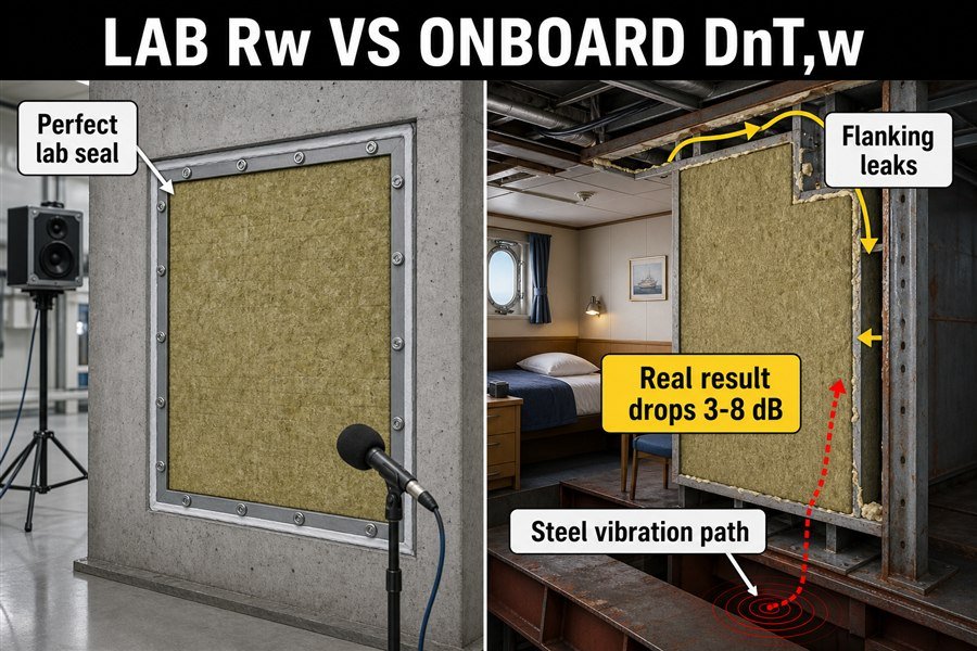
When I first started working at the shipyard, this gap between paper specifications and real ship noise drove me crazy. My clients would buy high-quality panels, but the crew could still hear engine noise in their rooms. Here is how we break down the problem and fix it.
Why Is a Marine Accommodation Panel's Field DnT,w Lower than Its Lab Rw?
Confused by different acoustic ratings? Expecting lab-level silence onboard only to hear the engine hum? This acoustic rating difference causes major project rejections during sea trials.
A marine panel's field sound insulation (DnT,w) is always 3 to 8 dB lower than its lab rating (Rw) because Rw measures only direct transmission through the panel in a controlled frame, whereas DnT,w measures all real-world sound paths, including leaks through ceilings, floors, and adjacent bulkheads.
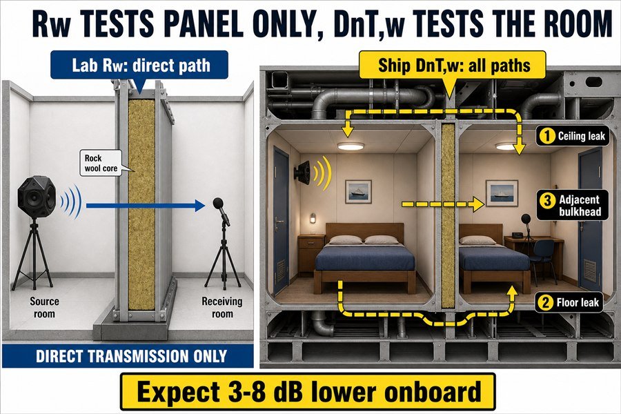
Lab ratings and field ratings test two completely different things. We need to look closely at the standards behind the numbers to understand why you get a lower result on the ship.
Understanding the Lab Rw Measurement for Panels
When a factory tests a marine wall panel, they use the ISO 140-3 standard1. They take a perfect 10-square-meter panel and place it inside a heavy concrete laboratory room. The lab seals the edges perfectly with heavy acoustic putty. The test measures only the sound traveling directly through the face of the panel2. We call this the Sound Reduction Index, or Rw. This number shows the maximum potential of the material itself. A standard 50mm thick rockwool marine panel usually scores an Rw of 33 dB to 35 dB. But this environment does not exist on a ship. A ship is a moving steel structure with pipes, wires, and air ducts everywhere. The lab test ignores all these real-world details.
Why DnT,w Reflects Real-World Ship Conditions
When inspectors test the noise on your actual ship during sea trials, they use the ISO 140-4 standard. This measures the Weighted Standardized Level Difference, or DnT,w. This test measures the noise drop from one actual cabin to the next. The microphone picks up sound traveling through the panel, but it also picks up sound bouncing through the steel deck, sneaking over the ceiling panel, and vibrating through the air conditioning ducts. Because sound always finds the easiest path, the total noise reduction drops. According to guidelines based on IMO Resolution A.468(XII), you should always expect the field DnT,w to be 3 to 8 dB lower than the factory Rw. If you need a cabin to hit a strict 30 dB noise limit, you cannot just buy a 30 dB Rw panel. You must buy a 35 dB or 38 dB Rw panel to give yourself enough safety margin for the real ship environment.
| Rating Type | Standard Used | Test Environment | What It Measures | Typical Result for 50mm Panel |
|---|---|---|---|---|
| Rw | ISO 140-3 | Concrete Lab | Panel material only | 35 dB |
| DnT,w | ISO 140-4 | Real Ship | Total room system | 27 dB to 32 dB |
What STL Loss Occurs Between Lab and Onboard Marine Accommodation Panel Installation?
Worried your expensive interior panels will fail the noise test at sea? Sound transmission loss drops significantly after the crew installs them. Let us look at the exact numbers you lose.
Between lab and onboard installation, marine panels typically experience an STL loss of 3 to 5 dB for standard cabins and 5 to 10 dB for engine room boundaries. This loss stems from three factors: flanking noise, imperfect edge sealing, and structural vibrations passing through the steel deck.
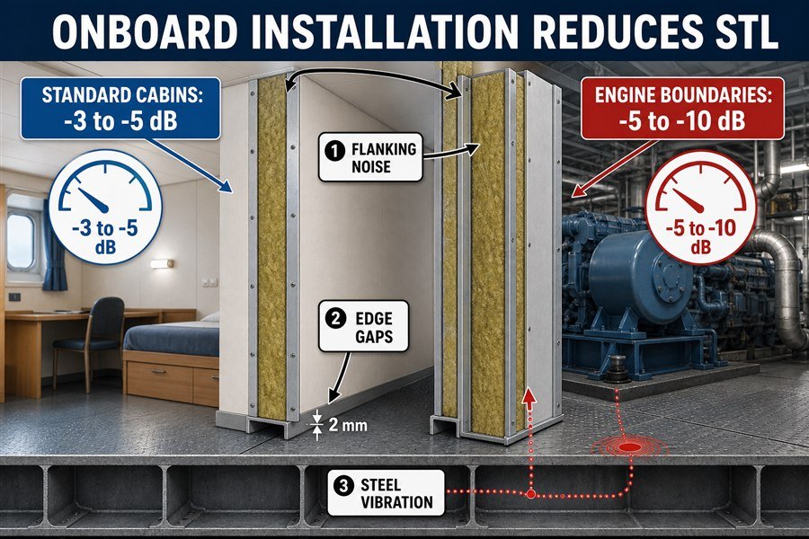
Knowing the exact Sound Transmission Loss (STL) drop helps you buy the right panels. You do not want to spend too much money, but you also cannot fail the shipyard inspection. Let us break down how much sound reduction you lose and the three reasons why it happens.
Quantifying STL Loss in Standard Cabins and Engine Rooms
The location of your panel changes how much sound reduction you lose. For standard crew cabins located on upper decks far away from heavy machinery, the STL loss is usually small. You will lose about 3 to 5 dB between the lab sheet and the final ship test.3 For example, a 50mm panel rated at 35 dB Rw will perform around 31 dB onboard. This is usually fine for standard IMO noise limits, which require around 60 dB maximum ambient noise in crew spaces.
However, the situation changes for engine room boundaries or main deck areas near the thrusters. In these high-noise zones, the STL loss jumps to 5 to 10 dB. The low-frequency noise from diesel engines hits the panels much harder than high-frequency noise.4 A heavy 100mm double-skin panel might test at 45 dB in the lab but only deliver 35 dB on the ship.
The Three Factors Driving STL Loss Onboard
Three specific problems cause this massive drop in performance. First, we have flanking noise. This is sound that simply goes around the panel instead of through it. Second, we have imperfect edge sealing. In the lab, workers spend hours sealing the panel edges with putty. On a fast-paced shipyard, workers often install the steel U-profiles and slide the panels in without adding acoustic sealant at the base. A tiny 2mm gap under a wall panel can destroy the sound rating of the entire wall.5 Third, we have structural vibrations. The ship engine shakes the raw steel deck. The steel deck shakes the metal U-profile track. The track shakes the wall panel. The panel turns into a giant speaker, creating noise directly inside the cabin. We must address all three factors to close the gap between lab data and sea trial results.
| Installation Zone | Expected STL Loss | Main Type of Noise | Panel Strategy |
|---|---|---|---|
| Standard Crew Cabins | 3 to 5 dB | Airborne noise | Add +5 dB to lab requirement |
| Public Spaces / Mess Rooms | 4 to 6 dB | Speech / Airborne | Add +5 dB to lab requirement |
| Engine Room Boundaries | 5 to 10 dB | Low-frequency vibration | Add +10 dB to lab requirement |
| Thruster / Bow Areas | 7 to 10 dB | High-impact vibration | Add +10 dB to lab requirement |
How Does Flanking Transmission Bypass Marine Accommodation Panel STL?
You sealed the cabin walls perfectly, but sound still travels between rooms. How is the noise getting through? Flanking transmission is the hidden enemy ruining your cabin acoustics.
Flanking transmission bypasses marine panel STL by traveling through four indirect paths: shared continuous ceiling voids, continuous floating floors, ventilation HVAC ducts, and the structural steel hull. Sound energy ignores the high-rated wall panel and vibrates through these weaker, unsealed connecting structures instead.
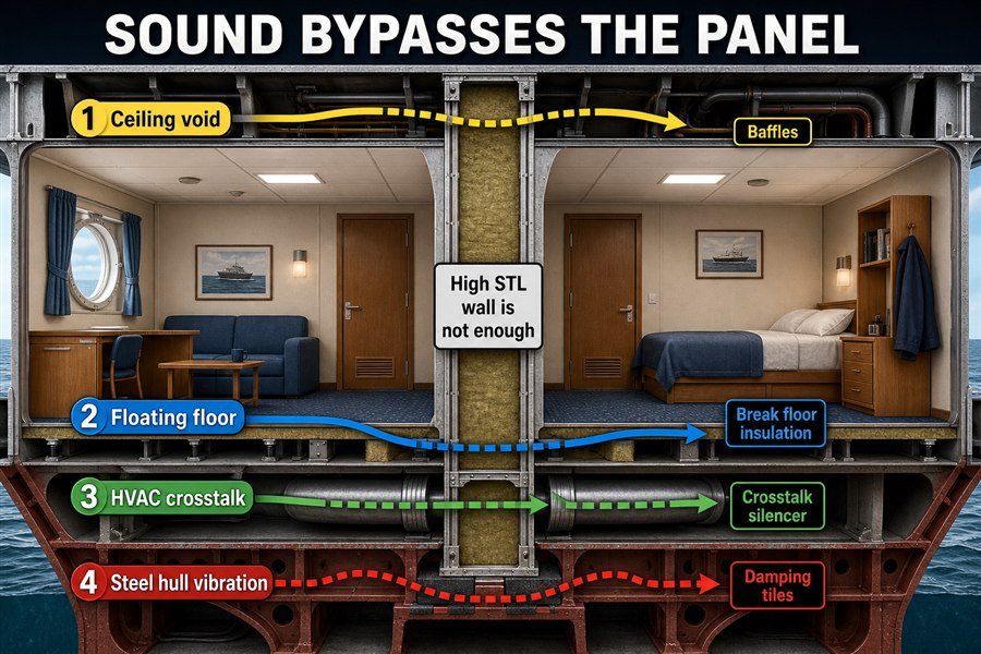
Imagine pouring water into a bucket with a hole in the side. It does not matter how strong the bottom of the bucket is. The water will escape. Sound works the same way. Sound energy always takes the easiest route.6
Flanking Paths Through Ceilings and Floating Floors
The first two flanking paths involve the spaces above and below the cabin. Many shipyards use a continuous floating floor across a whole deck, and they use a continuous ceiling panel system above the cabins. They install the vertical accommodation wall panels between the floor and the ceiling. This is a huge mistake. Sound from Cabin A goes up through the ceiling panel, travels freely through the empty void space under the steel deck, and comes down through the ceiling panel of Cabin B.7 The sound completely skips the expensive 40 dB wall you placed between them. The same thing happens with floors. If the rockwool base under the floating floor is not broken between rooms, heavy footsteps in one cabin will travel under the wall panel into the next room. To stop this, you must install vertical acoustic baffles inside the ceiling voids directly above the wall panels.
Flanking Paths Via HVAC Ducts and the Steel Hull
The third path is the ventilation system. HVAC ducts connect multiple cabins to supply fresh air. If someone talks loudly in one cabin, the sound enters the air vent, travels down the thin metal pipe, and exits the vent in the next cabin. This is called crosstalk.8 To fix this, you must install HVAC crosstalk silencers. According to ISO 7235 testing, a good silencer provides an insertion loss of 10 to 15 dB. The fourth path is the steel hull itself. Sound hits a steel bulkhead, travels through the bare steel, and radiates out into the next room. We apply damping tiles directly to the raw steel to absorb this energy before it travels. If you do not block all four of these paths, your expensive wall panels are wasting your money.
| Flanking Path | How Sound Travels | The Practical Solution | Expected Improvement |
|---|---|---|---|
| Ceiling Voids | Over the top of the wall | Install mineral wool vertical baffles | +4 to +6 dB |
| Floating Floors | Under the bottom of the wall | Cut floor insulation at wall line | +3 to +5 dB |
| HVAC Ducts | Through shared air pipes | Add crosstalk silencers to vents | +10 to +15 dB |
| Steel Hull | Through the ship structure | Apply damping tiles to bare steel | +3 to +5 dB |
How Do Direct Steel Connections Degrade Marine Accommodation Panel STL?
Mounting interior panels directly to the bare steel hull seems strong and safe. But it turns your quiet cabin into a giant speaker. Direct connections destroy sound ratings.
Direct steel connections degrade marine panel STL by acting as acoustic bridges, transferring low-frequency hull vibrations (20Hz to 200Hz) directly into the cabin panels. This structural-borne noise bypasses airborne acoustic insulation, causing up to a 12 dB drop in overall sound reduction performance onboard.
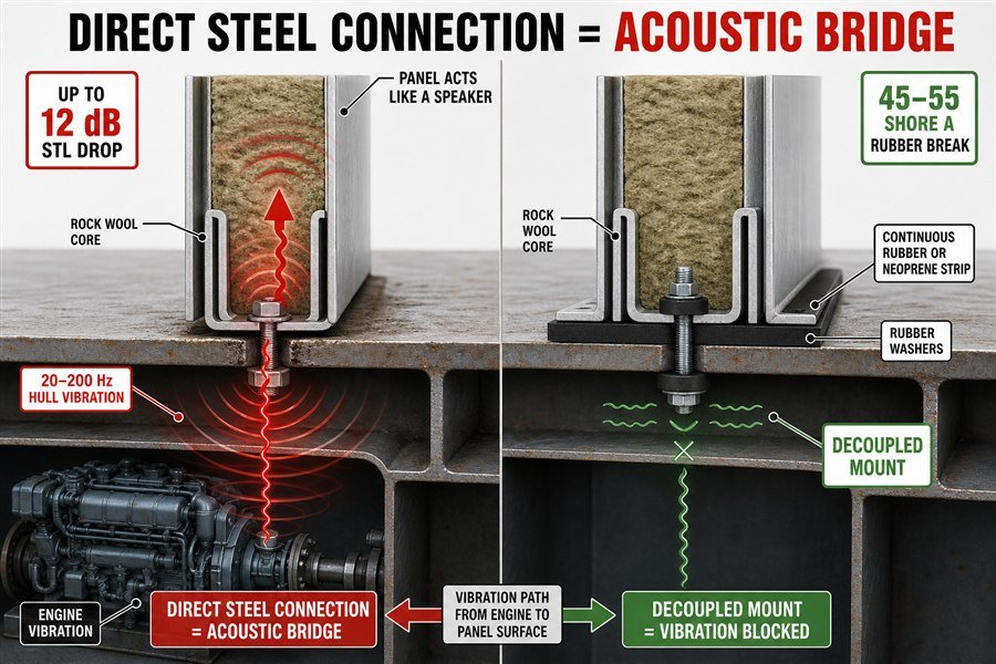
When I visit a noisy ship, I always look at the floor tracks first. If the shipyard screwed the metal panel tracks straight into the steel deck without any rubber, I know immediately why the cabins are loud.
The Mechanics of Structural-Borne Noise Transfer in Panels
A ship is essentially a giant metal box sitting in water. Deep inside the ship, massive diesel engines and generators spin constantly. These machines create huge amounts of low-frequency vibration, usually between 20Hz and 200Hz9. This vibration travels through the steel hull with almost zero energy loss. When you weld or bolt a steel U-profile directly to that vibrating steel deck, the vibration transfers straight into the U-profile. Then, when you insert a metal-faced marine accommodation panel into that profile, the panel starts vibrating too. The entire wall becomes a speaker cone pushing noise into the room. This is called structural-borne noise10. A panel can have a massive 50 dB airborne noise rating from the factory, but it cannot stop structural noise. Direct connections can ruin your acoustic performance by up to 12 dB11, making it impossible to pass the ISO 20283-5 ship vibration and noise limits.
Preventing Degradation with Resilient Mounting Systems
We must break the physical metal-to-metal connection. We call this decoupling. You must use a resilient mounting system. Instead of placing the steel U-profile directly on the deck, you place a continuous strip of high-density rubber or neoprene under the profile. This rubber acts as an acoustic break. The rubber needs to have a specific hardness, usually around 45 to 55 Shore A12. If the rubber is too soft, the heavy walls will crush it. If the rubber is too hard, it will pass the vibration through just like steel. You must also use rubber washers on the screws that hold the profile to the deck. If you use a rubber mat but still drive a bare steel screw straight through the track into the deck, you just created a new acoustic bridge. Using proper rubber isolators adds very little cost but saves your entire acoustic design.
| Connection Method | Vibration Transfer Level | Impact on Panel STL | Best Use Case |
|---|---|---|---|
| Direct Steel Bolt / Weld | Very High | -8 to -12 dB drop | Cargo holds only |
| Standard Floating Floor Base | Medium | -3 to -5 dB drop | Standard crew cabins |
| Rubber Base Isolator (45 Shore A) | Low | -1 to -2 dB drop | Passenger cabins |
| Full Resilient Mount with Rubber Washers | Very Low | 0 dB drop | Engine control rooms |
Why Does System Design Matter More than Individual Marine Accommodation Panel STL?
Buying the highest-rated wall panel will not guarantee a quiet cabin. Spending extra budget on thicker panels often wastes your money. System design is what actually matters.
System design matters more than individual panel STL because the overall acoustic performance is dictated by the weakest link in the room. A 45 dB panel system will only achieve 30 dB if the doors, windows, ceiling joints, and deck floating systems only provide a 30 dB reduction.
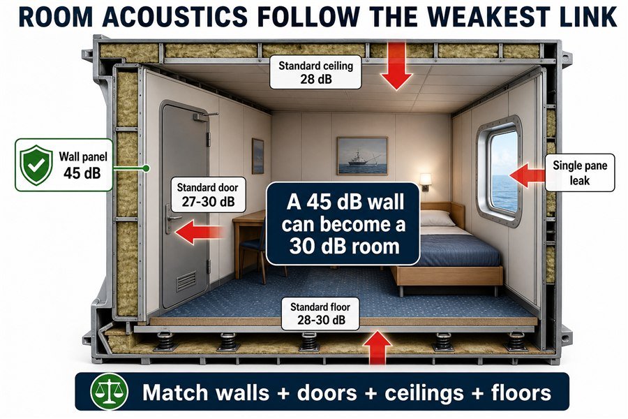
Many buyers make a classic mistake. They see a strict noise requirement from the shipowner, so they spend their whole budget buying the thickest, heaviest wall panels on the market. Then the ship fails the noise test anyway.
Identifying the Weakest Acoustic Link in Cabins
Acoustics follow the weakest link principle. We use a formula called the composite sound reduction index to prove this. Imagine you build a bulkhead wall that is 10 square meters in total. You use amazing wall panels that block 45 dB of sound. But in the middle of this wall, you install a standard B-15 marine fire door. This door is 2 square meters in size and only blocks 30 dB of sound. Because sound energy rushes through the weakest path13, the 30 dB door completely ruins the 45 dB wall. The composite sound reduction for that entire 10-square-meter wall drops to just 32 dB14. You paid for 45 dB, but you only get 32 dB. All the extra money you spent on the premium wall panels was totally wasted. You would get the exact same room performance if you just bought standard 33 dB wall panels.
Integrating Doors and Floors into Panel System Design
To pass the IMO A.468(XII) noise limits, you must design the room as a complete acoustic system. You need to balance the components. If you buy a 35 dB wall panel, you should buy a heavy acoustic marine door that hits at least 33 dB to match it. You must also look at the windows. A standard single-pane marine window will leak massive amounts of noise. You need double-glazed acoustic glass to match your wall panels. Finally, check the ceiling. Standard 25mm thick ceilings only offer about 28 dB of reduction15. If you need a quiet room, you must upgrade the ceiling to a 50mm panel to match your walls. A smart procurement officer balances the budget across the walls, doors, ceilings, and floors so that every single component provides roughly the same sound reduction.
| Component in the Cabin | Product Rating | Resulting Room Rating | Diagnosis |
|---|---|---|---|
| Wall Panel Only | 45 dB | 45 dB | Perfect Lab Test |
| Wall + Standard Door | 45 dB + 27 dB | 29 dB | Wasted wall panel money |
| Wall + Acoustic Door | 45 dB + 40 dB | 41 dB | Good system balance |
| Wall + Standard Ceiling | 45 dB + 28 dB | 30 dB | Noise escapes over the wall |
Which Installation Errors Most Drop a Marine Accommodation Panel's Onboard Rw?
Even the best acoustic system fails if installed wrong. Are your shipyard workers making basic mistakes? These common installation errors destroy your expensive acoustic ratings.
The three installation errors that most drop a marine panel's onboard Rw are: missing acoustic sealant at U-profile base joints (losing 3-5 dB), overtightening anti-vibration rubber mounts until they become rigid (losing 4-6 dB), and leaving unsealed gaps around cable penetrations (losing up to 10 dB).
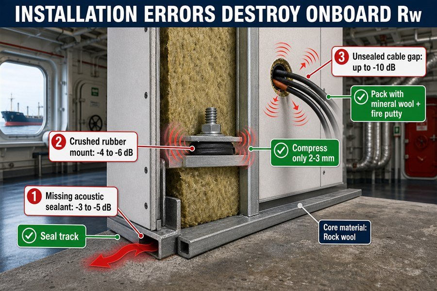
I spend a lot of time walking through shipyards during the outfitting phase. I watch the workers install the products I sold. The panels themselves never fail. The installation methods fail. Let us look at the three biggest mistakes that kill acoustic performance.
Error 1 and 2: Sealant Failures and Overtightened Mounts
The first major error is missing acoustic sealant at the base. When workers lay down the bottom U-profile track on the deck, the steel deck is rarely perfectly flat. Small gaps exist between the track and the floor. When you slide the wall panel into the track, noise escapes through those tiny gaps. Workers must apply a continuous bead of flexible polyurethane acoustic sealant under every single bottom track. Skipping this simple step causes a 3 to 5 dB loss.16
The second major error is overtightening the anti-vibration rubber mounts. We talked earlier about using 45 Shore A rubber strips under the tracks to stop engine vibration. However, many workers use power drills to drive the mounting bolts deep into the deck. They tighten the bolts so hard that the rubber crushes completely flat. When rubber is crushed totally flat, it loses all its flexibility. It becomes just as rigid as the steel itself.17 The acoustic bridge is restored, and you lose 4 to 6 dB of performance18. Bolts should be tightened only enough to hold the track secure; the rubber should compress no more than 2 to 3 millimeters.
Error 3: The Massive Impact of Cable Penetration Gaps
The third and worst error is unsealed cable penetrations. Modern ship cabins need power cables, light switches, and data lines. Electricians cut holes in your beautiful 40 dB wall panels to run their wires. Very often, they leave a 10mm gap around a 5mm wire. A hole the size of a pencil can leak enough sound to drop a wall's performance by up to 10 dB.19 Fire ratings require workers to pack these holes eventually, but they often just use standard expanding foam. Standard foam has almost zero acoustic mass. Every single cable penetration must be packed tightly with high-density mineral wool and sealed on both sides with specialized acoustic fire putty.
| Installation Error | Cause of Sound Leak | Expected dB Loss | The Correct Fix |
|---|---|---|---|
| Missing Base Sealant | Uneven deck leaves gaps under U-profile | 3 to 5 dB | Apply polyurethane sealant under tracks |
| Overtightened Rubber | Crushed rubber transfers hull vibration | 4 to 6 dB | Do not compress rubber past 3mm |
| Unsealed Cable Gaps | Airborne sound travels through empty holes | 8 to 10 dB | Pack gaps with acoustic fire putty |
| Standard Foam in Holes | Low-mass foam cannot stop sound waves | 5 to 7 dB | Use high-density mineral wool packing |
Conclusion
Lab ratings sell panels, but field installation dictates the actual noise on the ship. By stopping flanking paths, isolating vibrations, balancing doors, and sealing gaps, you secure true onboard silence.
-
"Sound reduction index - Wikipedia", https://en.wikipedia.org/wiki/Sound_reduction_index. ISO 140-3 specifies laboratory measurement procedures for airborne sound insulation of building elements and provides the basis for deriving sound reduction ratings such as Rw under controlled mounting conditions. Evidence role: definition; source type: institution. Supports: Factory laboratory panel tests use ISO 140-3 to measure airborne sound insulation and derive Rw-type ratings. Scope note: The ISO 140 series has been superseded in many current contexts by ISO 10140 and ISO 717, so the citation should clarify the historical or applicable regulatory context. ↩
-
"Validation of a 1:8 Scale Measurement Stand for Testing ...", https://pmc.ncbi.nlm.nih.gov/articles/PMC8512408/. Laboratory airborne sound-insulation tests are designed to measure direct transmission through the specimen while minimizing flanking transmission through the surrounding test construction and mounting details. Evidence role: mechanism; source type: education. Supports: A laboratory Rw test is intended to isolate direct sound transmission through the panel rather than shipboard flanking paths. Scope note: This supports the testing principle; actual laboratories may still require correction or validation procedures to control residual flanking effects. ↩
-
"[PDF] sound insulation evaluations of several single-row-of-wood-stud ...", https://www.fpl.fs.usda.gov/documnts/fplrp/fplrp241.pdf. Field-measurement literature on shipboard partitions reports that in-situ airborne sound insulation can be lower than laboratory ratings because of flanking paths, installation tolerances, and boundary conditions, supporting the use of a field-loss allowance for accommodation spaces. Evidence role: statistic; source type: paper. Supports: Standard crew cabins may show an STL loss of about 3 to 5 dB between laboratory ratings and onboard testing.. Scope note: The source may support the general magnitude and causes of lab-to-field degradation, but may not verify the exact 3-5 dB range for every standard crew cabin design. ↩
-
"[PDF] Sound Transmission Loss of Composite Sandwich Panels", https://etd.auburn.edu/bitstream/10415/1702/3/Ran%20Zhou_Dissertation.pdf. Acoustics references on ship noise and sound transmission explain that diesel machinery produces substantial low-frequency components and that partitions generally provide lower transmission loss at low frequencies than at mid and high frequencies, supporting the mechanism described here. Evidence role: mechanism; source type: paper. Supports: Diesel-engine low-frequency noise is more difficult for panels to block than higher-frequency airborne noise. Scope note: This supports the physical mechanism, not the precise STL loss for any particular panel construction or engine-room boundary. ↩
-
"[PDF] Investigation of transmission loss through double wall structures with ...", https://ir.library.louisville.edu/cgi/viewcontent.cgi?referer=&httpsredir=1&article=2758&context=etd. Building-acoustics guidance and leakage studies show that small unsealed gaps or openings can disproportionately reduce the effective sound insulation of an otherwise high-rated partition, supporting the warning that edge gaps can dominate wall performance. Evidence role: mechanism; source type: research. Supports: Even a very small unsealed gap under a wall panel can substantially reduce the effective sound rating of the wall. Scope note: The evidence typically demonstrates the effect of small leaks in general partitions; the exact impact of a 2 mm gap depends on wall area, gap length, frequency, and installation details. ↩
-
"[PDF] Review of Modelling and Prediction Methods for Flanking ...", https://upcommons.upc.edu/bitstreams/61ecb1e5-2d31-4e5a-9331-36438f565f22/download. Acoustics references describe flanking transmission as sound reaching a receiving room by indirect paths around the separating element, supporting the statement that weak indirect paths can dominate overall isolation. Evidence role: mechanism; source type: education. Supports: Sound isolation can be limited by indirect flanking transmission paths rather than by the nominal rating of the separating wall alone.. Scope note: This supports the physical mechanism in general building acoustics; it does not quantify the specific ship-cabin examples in the article. ↩
-
"[PDF] OPEN-PLAN OFFICE SPACES AND THEIR ACOUSTIC ...", https://www.arc.miami.edu/_assets/pdf/acoustics_shannaroconnor_stantec.pdf. Guidance on flanking transmission through suspended ceilings and ceiling voids supports the mechanism by which sound can bypass partitions via a continuous plenum or ceiling cavity. Evidence role: mechanism; source type: institution. Supports: A continuous ceiling void or plenum can act as a flanking path that bypasses vertical partitions between rooms.. Scope note: The evidence is likely to come from building-acoustics guidance; it is directly relevant to the mechanism but may not be specific to ship accommodation interiors. ↩
-
"[PDF] LEVEL II FEASIBILITY STUDY FINE & PERFORMING ARTS ...", https://www.lccc.wy.edu/Documents/About/Board/Agendas/2017/September_20/Fine%20Arts%20Draft%20Level%20II%20Plan.pdf. HVAC acoustics literature defines duct-borne crosstalk as sound transmission between rooms through connected ventilation ductwork, supporting the described pathway through shared air vents. Evidence role: definition; source type: education. Supports: Shared HVAC ducts can transmit speech or other airborne noise between rooms, a phenomenon commonly referred to as crosstalk.. Scope note: The source would establish the general definition and pathway; actual severity depends on duct layout, airflow devices, and room finishes. ↩
-
"[PDF] Carbon Fiber Substitution in Shipboard Instrument Structural Mounts ...", https://dspace.mit.edu/server/api/core/bitstreams/d19a9bed-c9a6-4399-9a7f-ef6e31114552/content. Studies of shipboard diesel machinery and onboard vibration commonly identify dominant low-frequency components associated with machinery operation and engine orders, including frequencies within the 20-200 Hz band. Evidence role: statistic; source type: paper. Supports: Shipboard diesel engines and generators commonly create low-frequency vibration in the 20-200 Hz range.. Scope note: The exact frequency range depends on engine speed, mounting, hull structure, and operating condition, so the source would contextualize rather than universally prove this range for every ship. ↩
-
"Characterisation of Structure-Borne Sound Source Using Reception ...", https://pmc.ncbi.nlm.nih.gov/articles/PMC3842046/. Acoustics references define structure-borne sound as sound generated when vibration is transmitted through solid structures and then radiated as airborne sound from connected surfaces. Evidence role: definition; source type: institution. Supports: Noise radiated by panels after vibration travels through steel connections is structural-borne noise. ↩
-
"How to Balance Acoustic Insulation and Structural Thickness in ...", https://magellanmarinetech.com/how-balance-acoustic-insulation-and-structural-thickness-retrofit-marine-panels/. Research on flanking transmission and resiliently mounted partitions shows that rigid structural connections can reduce apparent sound insulation relative to laboratory panel ratings by creating vibration transmission paths. Evidence role: general_support; source type: paper. Supports: Rigid metal-to-metal connections can substantially reduce the acoustic performance of otherwise high-rated panels. Scope note: Published results are assembly-specific; a source may support the mechanism and comparable losses, but the exact 12 dB figure must match a tested configuration to be direct proof. ↩
-
"[PDF] Introduction to Designing Elastomeric Vibration Isolators Christopher ...", https://wp.optics.arizona.edu/optomech/wp-content/uploads/sites/53/2016/10/521_Tutoral_Hopkins.pdf. Elastomer vibration-isolation design literature explains that rubber hardness, commonly measured on the Shore A scale, affects stiffness, load deflection, and vibration transmissibility of isolation mounts. Evidence role: mechanism; source type: research. Supports: Rubber isolators for panel tracks require an appropriate Shore A hardness, with the article specifying about 45-55 Shore A.. Scope note: This supports why hardness matters, but a separate marine assembly test or manufacturer-independent specification would be needed to verify that 45-55 Shore A is the optimal range for these panel tracks. ↩
-
"[PDF] MODELING THE TRANSMISSION LOSS OF TYPICAL HOME ...", https://repository.gatech.edu/server/api/core/bitstreams/124b4a58-8706-4fc8-9139-9b18ed96233e/content. Building-acoustics treatments of composite partitions explain that total sound transmission is calculated from the area-weighted transmission coefficients of each element, so a lower-rated door or opening can disproportionately reduce the overall partition rating. Evidence role: mechanism; source type: education. Supports: A weaker acoustic element such as a door can dominate the effective sound reduction of an otherwise higher-rated wall. Scope note: This supports the acoustic mechanism in general, not the specific product ratings or numerical example used in the article. ↩
-
"Frequency domain characterisation of the sound insulation performance of ...", https://pmc.ncbi.nlm.nih.gov/articles/PMC12307673/. A source defining the composite sound reduction index formula would document the calculation method used to combine a high-rated wall area with a lower-rated door area; it would not independently verify the article's exact arithmetic or include flanking transmission unless those conditions are specified. Evidence role: mechanism; source type: paper. Supports: The composite sound reduction for the stated wall-and-door assembly drops to the article's stated overall value.. Scope note: The cited source would be contextual unless it reproduces the same 10 m2, 45 dB wall, 2 m2, 30 dB door example. ↩
-
"How to choose the right marine wall panels for marine interior projects?", https://magellanmarinetech.com/how-choose-right-marine-wall-panels-for-marine-interior-projects/. An independent acoustic test report or classification-society certificate for marine ceiling panels reporting weighted sound reduction by panel thickness would support the approximate 28 dB figure for a 25 mm ceiling construction. Evidence role: statistic; source type: institution. Supports: Standard 25 mm marine ceiling panels provide about 28 dB of sound reduction.. Scope note: The value is product- and installation-specific; it should not be generalized to all 25 mm ceiling systems without matching construction, mounting, and test conditions. ↩
-
"[PDF] Investigation of transmission loss through double wall structures with ...", https://ir.library.louisville.edu/cgi/viewcontent.cgi?referer=&httpsredir=1&article=2758&context=etd. A building-acoustics field or laboratory source should support that small unsealed perimeter gaps and flanking paths can measurably reduce the apparent sound reduction of partition assemblies; the cited evidence may contextualize the magnitude rather than verify the exact 3-5 dB range for shipyard U-profile tracks. Evidence role: statistic; source type: paper. Supports: Omitting continuous acoustic sealant under bottom tracks can reduce wall acoustic performance by about 3 to 5 dB.. Scope note: Likely support will be contextual unless it tests the same marine panel, deck profile, sealant type, and installation geometry. ↩
-
"[PDF] Analysis of Mounting Layouts for Improved Vibration Isolation ...", https://kb.osu.edu/bitstreams/3e2e2a75-4641-5fd1-a9a2-903adc4b8bbc/download. A vibration-isolation engineering source should support the principle that elastomeric isolators require deflection and compliance to provide isolation, and that excessive compression or bottoming-out creates a stiff mechanical path; this supports the mechanism rather than the article's exact shipboard installation details. Evidence role: mechanism; source type: education. Supports: Over-compressing rubber mounts reduces their vibration-isolation function by creating a stiff mechanical bridge.. Scope note: The source may address elastomer isolators generally rather than 45 Shore A rubber strips in marine wall tracks. ↩
-
"Airborne sound insulation performance of lightweight double ...", https://pmc.ncbi.nlm.nih.gov/articles/PMC11666719/. A controlled acoustic or vibration-isolation test source should document the performance penalty associated with rigidly coupled or improperly compressed resilient mounts; if the source concerns analogous building or machinery mounts, it should be treated as contextual support for the 4-6 dB figure. Evidence role: statistic; source type: paper. Supports: Overtightening or short-circuiting resilient mounts can reduce acoustic performance by roughly 4 to 6 dB.. Scope note: Exact decibel loss may vary with mount hardness, fastener spacing, panel mass, excitation frequency, and ship structure. ↩
-
"[PDF] Sound insulation of wall and floor constructions - GovInfo.gov", https://www.govinfo.gov/content/pkg/GOVPUB-C13-ba6463f3e57c48f63cbb93037927886e/pdf/GOVPUB-C13-ba6463f3e57c48f63cbb93037927886e.pdf. A building-acoustics reference or laboratory study should support that small penetrations and air leaks can disproportionately degrade the measured sound insulation of otherwise high-performing partitions; the citation may substantiate the general effect rather than the exact pencil-sized-hole scenario. Evidence role: statistic; source type: paper. Supports: Small unsealed cable penetrations can significantly reduce a wall's sound insulation, potentially by up to about 10 dB.. Scope note: The precise loss depends on wall rating, hole area, frequency range, cavity treatment, and whether the penetration is sealed on one or both sides. ↩