
You buy high-Rw panels, but cabin noise remains unbearable. Poor installation ruins acoustic performance. I will show you how installation mistakes destroy Sound Transmission Loss and how to fix them.
Installation affects marine wall panel STL by introducing structural flanking paths, unsealed joints, poor U-profile mounting, and unmanaged penetrations. These four installation failures can reduce a panel's laboratory-tested Rw rating by 5 to 15 dB in the field, compromising crew comfort and violating IMO noise regulations.
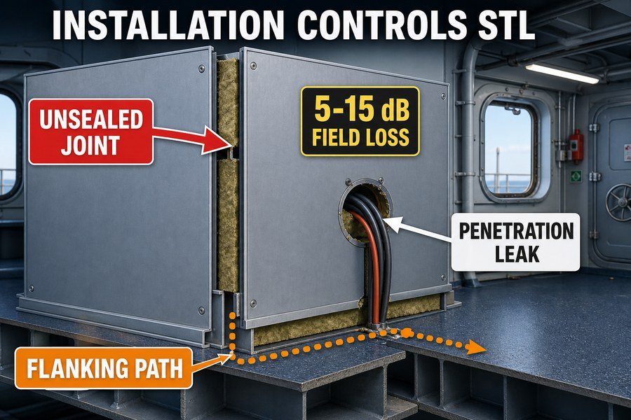
Let us look at the specific installation issues that cause these acoustic failures on board a ship.
How Do Spline Joints Reduce Effective Marine Wall Panel Rw?
You join panels perfectly, but voices still bleed through. Standard spline joints create weak points. We need to understand why these joints leak sound to protect your acoustic rating.
Spline joints reduce effective marine wall panel Rw because they create a physical break in the insulation core, lack continuous mass, and often have microscopic air gaps. These three factors combine to cause sound wave diffraction, dropping the overall wall performance by 3 to 5 dB.
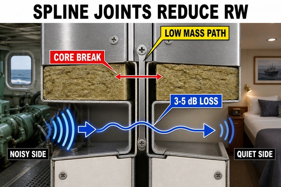
Addressing the Physical Break and Lack of Continuous Mass
Marine wall panels normally use a steel skin and a mineral wool core. The steel skin is usually 0.6mm thick. The mineral wool core usually has a density of 120 kg/m3. This heavy core blocks sound. You use a metal spline to connect two panels. This creates a problem. The mineral wool stops at the edge of the panel. The rockwool from the first panel does not touch the rockwool from the second panel. This creates a physical break in the insulation core. Sound travels easily through this break.
The joint also lacks continuous mass. The thin steel spline connects the skins. It does not have the mass of the 120 kg/m3 mineral wool. Sound barriers need heavy mass to stop low-frequency noise.1 The spline joint has very low mass. Therefore, sound passes straight through the connection point. According to the IMO Resolution MSC.337(91) code on noise levels, you need specific Rw ratings for cabins. A standard 50mm panel might test at 35 dB in a lab. The lack of mass at the joints drops the field performance significantly below the required limit.
Eliminating Microscopic Air Gaps in Panel Joints
The third problem is air gaps. You push two metal panels together. They look tight. However, metal against metal is never totally flat. Microscopic air gaps always exist. Sound behaves like water. It finds the smallest hole and flows through it. High-frequency sound waves diffract through these tiny air gaps.
This diffraction reduces the effective Rw by 3 to 5 dB.2 This number comes from field tests based on the ISO 16283-1 standard. You must fix these three issues during installation. You must apply a flexible, fire-resistant acoustic sealant inside the joint before you insert the spline. This sealant fills the air gaps. It also adds a small amount of mass back to the joint. You must never leave metal joints dry if you want good acoustic results.
| Joint Condition | Physical Break | Continuous Mass | Microscopic Air Gaps | Expected Field Rw Drop |
|---|---|---|---|---|
| Dry Spline Joint | Yes | No | Yes | 3 to 5 dB loss |
| Sealed Spline Joint | Yes | Partially Restored | No | 1 to 2 dB loss |
| Double Spline with Sealant | Minimal | Yes | No | 0 to 1 dB loss |
Why Do Bottom U-Profiles Cause Sound Leaks in Marine Wall Panels?
You install heavy panels, but noise travels under them. Empty bottom tracks act like acoustic tunnels. I will explain why this happens and how to block the noise.
Bottom U-profiles cause sound leaks in marine wall panels because they create a hollow resonance chamber, lack acoustic packing, and transmit deck vibrations directly into the steel skins. These three issues allow flanking noise to bypass the thick mineral wool core entirely.
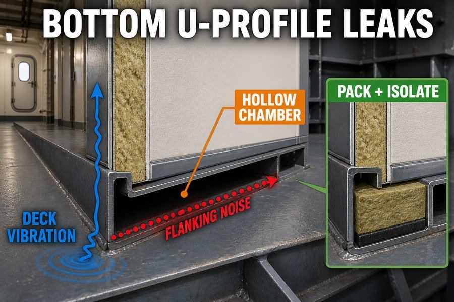
Fixing Hollow Resonance Chambers and the Lack of Acoustic Packing
A bottom U-profile is a piece of folded steel. You weld or screw it to the deck. Then you stand the marine wall panel inside it. This creates a hollow space under the panel. This space acts as a hollow resonance chamber3. Sound enters the steel profile. The empty space makes the sound echo and amplify. The noise travels along the track and enters the next cabin.
The main reason for this chamber is the lack of acoustic packing. Installers often leave the bottom U-profile completely empty. They just drop the panel in. The mineral wool inside the panel stops at the bottom edge. There is nothing but air between the panel bottom and the steel deck. Air is a very poor sound insulator.4 According to tests by rockwool manufacturers like Paroc and Rockwool Marine, an empty bottom track can reduce a wall's Sound Transmission Loss by 4 to 6 dB5. You must pack the U-profile. You must cut strips of high-density rockwool. The rockwool should have a density of at least 100 kg/m3. You push these strips into the U-profile before you install the panel. This fills the resonance chamber and blocks the sound path.
Preventing Deck Vibrations from Reaching the Panel
The third issue is vibration transmission. The steel deck vibrates constantly. The ship engine and propellers cause this vibration. The bottom U-profile sits directly on the hard steel deck. The steel U-profile touches the steel panel skins. This creates a direct metal-to-metal acoustic path.
The deck vibrations travel into the U-profile. The U-profile pushes the vibrations into the panel skins. The panel skins vibrate like a speaker cone. This creates noise inside the cabin. We call this structure-borne noise6. You must break this metal path. You should place a heavy rubber or polyurethane acoustic tape under the U-profile before you fasten it to the deck. This tape must be 3mm to 5mm thick. This tape stops the direct vibration transmission.
| U-Profile Condition | Resonance Chamber | Acoustic Packing Density | Vibration Isolation | Acoustic Performance Loss |
|---|---|---|---|---|
| Empty, directly on deck | Large | 0 kg/m3 | None | 4 to 6 dB loss |
| Packed, directly on deck | Eliminated | 100 kg/m3 | None | 2 to 3 dB loss |
| Packed, with acoustic tape | Eliminated | 100 kg/m3 | 3-5mm Rubber | 0 to 1 dB loss |
How Do Penetrations Degrade Marine Wall Panel STL?
Cables must pass through bulkheads, but every hole destroys your sound rating. Unsealed penetrations let noise pour in. Let us fix this common installation error immediately.
Penetrations degrade marine wall panel STL by removing core mass, creating direct air paths for high-frequency noise, and causing pipe resonance. These three penetration effects can reduce a 35 dB wall to a 20 dB wall if cable transit frames are not packed with high-density acoustic mastic.
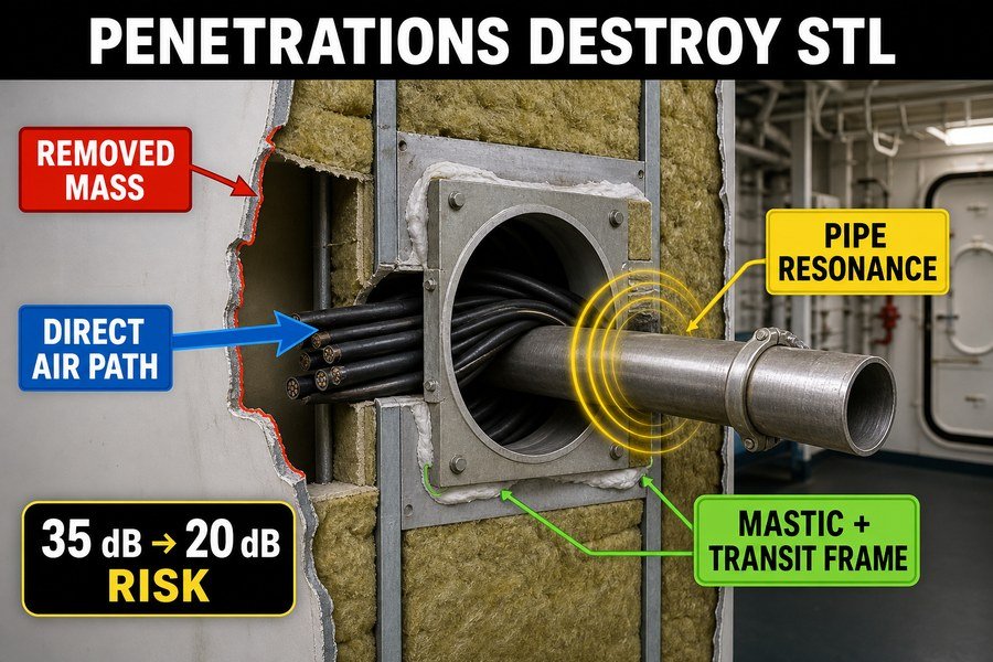
Replacing Removed Core Mass and Blocking Direct Air Paths
A ship needs cables and pipes. You must cut holes in the marine wall panels to let them pass. This cutting process destroys the panel's acoustic integrity. First, cutting a hole means removing core mass. You take away the heavy steel skin and the 120 kg/m3 mineral wool. You replace it with light plastic cables or empty air. Mass blocks sound.7 When you remove mass, you lose Sound Transmission Loss.
Second, a cutout creates direct air paths. Installers usually cut a hole that is larger than the pipe. They leave a gap around the pipe. Sound travels through this open air gap with zero resistance. High-frequency noise easily passes through these direct air paths. According to basic acoustic principles in DNV classification rules, if just 1% of a wall area is an open hole, a 40 dB panel will drop to a 20 dB panel8. This is a massive loss. You must fix this. You must use certified marine transit frames, like Roxtec systems. You pack the space around the cables with rubber blocks. You must also use heavy acoustic mastic. This replaces the lost mass and blocks all direct air paths.
Controlling Pipe Resonance in Marine Bulkheads
The third penetration effect is pipe resonance. A metal pipe passes through the bulkhead. Water or air flows through the pipe. This flow creates noise and vibration inside the pipe. The pipe itself rings like a bell.
If the hard metal pipe touches the cut edge of the steel wall panel, the pipe transfers its vibration into the wall9. The wall panel amplifies the pipe noise. This is pipe resonance. You must never let a bare pipe touch a bare panel edge. You must wrap the pipe with a flexible acoustic sleeve. You can use 25mm thick elastomeric foam. You place this foam between the pipe and the panel cutout. This stops the vibration transfer.10 It isolates the pipe resonance from the cabin wall.
| Penetration Type | Removed Core Mass | Direct Air Path | Pipe Resonance Risk | Acoustic Degradation |
|---|---|---|---|---|
| Open Hole (1% wall area) | Complete Loss | Yes | Low | 20 dB loss |
| Unsealed Bare Pipe | High Loss | Yes | High | 10 to 15 dB loss |
| Sealed Frame with Mastic | Restored | Blocked | Low | 1 to 2 dB loss |
| Isolated Pipe with Foam | Restored | Blocked | Eliminated | 0 to 1 dB loss |
How Does Single-Skin Versus Double-Skin Marine Wall Panel STL Compare?
You want to save money and space, so you choose single-skin panels. But the cabin becomes too noisy. We must compare their acoustic performance to make the right choice.
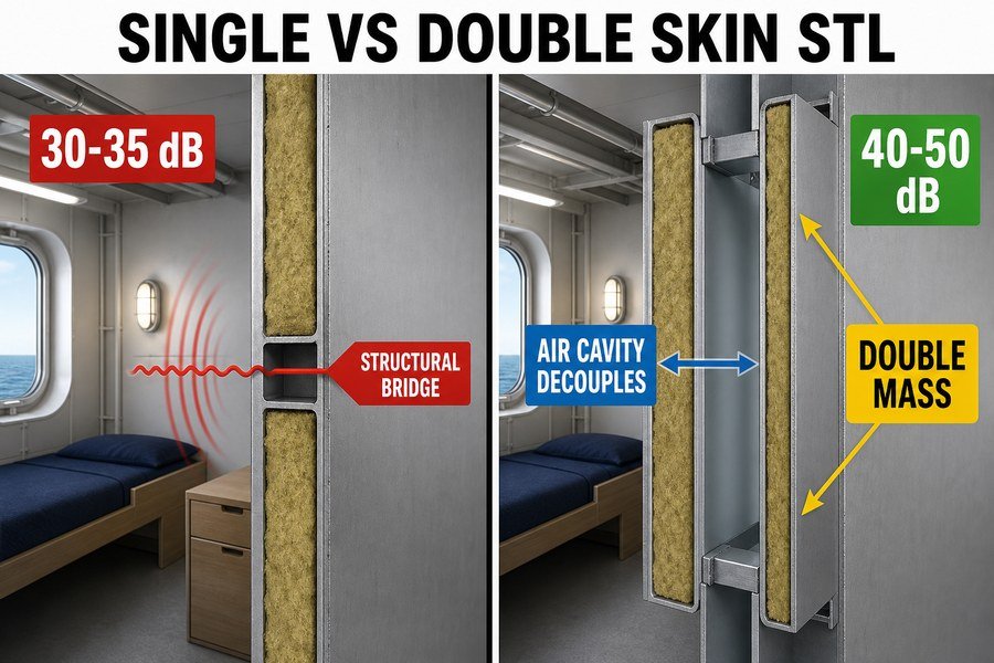
Single-skin marine wall panels typically achieve an STL of 30 to 35 dB, while double-skin panels with an air gap achieve 40 to 50 dB. This difference exists because double-skin systems break the structural sound bridge, add double mass, and utilize the air cavity for acoustic decoupling.
Breaking Structural Sound Bridges and Adding Double Mass
Shipbuilders use two main types of acoustic walls. A single-skin panel is one thick block. It has steel on both sides and mineral wool in the middle. A standard 50mm single-skin panel achieves an STL of 30 to 35 dB in lab tests.11 This is not enough for loud machinery spaces. The problem is the structural sound bridge. The metal edges and splines connect the two sides of the panel. When sound hits one side, the metal edge carries the vibration straight to the other side12.
A double-skin system solves this. You build two separate 25mm or 50mm walls. You leave a gap between them. This breaks the structural sound bridge. The vibration cannot travel from one wall to the other through the metal edges. Double-skin panels also add double mass. You have four layers of steel skin instead of two. More mass means better low-frequency sound blocking. According to ISO 717-1, doubling the mass of a partition can increase the STL by about 6 dB.
Utilizing the Air Cavity for Acoustic Decoupling
The most important feature of a double-skin system is the air cavity. You leave a 50mm to 100mm air gap between the two separate walls. This air cavity provides acoustic decoupling.
When sound hits the first wall, the wall vibrates. It pushes the air inside the cavity. The air acts like a soft spring. It absorbs the energy. The air does not push hard against the second wall. Therefore, the second wall stays quiet. This decoupling effect is very powerful for high-frequency noise. A single 50mm panel gives you 33 dB. A double-skin system with two 25mm panels and a 50mm air gap gives you 45 dB.13 The total thickness is 100mm. You use the same amount of material, but you get much better noise reduction. This is why luxury cruise ships always use double-skin systems around engine rooms.
| Panel Type | Total Thickness | Structural Bridge | Air Cavity | Estimated Lab Rw (STL) |
|---|---|---|---|---|
| Standard Single-Skin | 50mm | Yes (Metal Edges) | None | 33 to 35 dB |
| Heavy Single-Skin | 100mm | Yes (Metal Edges) | None | 38 to 40 dB |
| Standard Double-Skin | 100mm (25+50+25) | Broken | 50mm | 44 to 46 dB |
| Heavy Double-Skin | 150mm (50+50+50) | Broken | 50mm | 48 to 52 dB |
Why Do Marine Wall Panel Lab Tests Assume Unrealistic Edge Sealing?
Your supplier shows you a lab certificate with amazing Rw values. But your real ship fails the noise test. Let us expose the truth about laboratory testing methods.
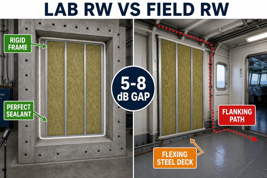
Marine wall panel lab tests assume unrealistic edge sealing because they use rigid concrete frames, apply heavy acoustic sealant to all perimeters, and eliminate structural flanking paths. These three ideal conditions do not exist on a ship, explaining the 5 to 8 dB difference between laboratory and field results.
The Problem with Rigid Concrete Frames and Heavy Acoustic Sealants
When a factory tests a marine wall panel, they send it to an acoustic laboratory. The lab follows the ISO 10140-2 standard. This standard uses very specific conditions. First, the lab builds the test wall inside a rigid concrete frame14. This concrete frame is usually 300mm thick. It is very heavy and totally stiff. On a ship, you install panels on a thin steel deck. The steel deck flexes and bends. It does not support the panel like solid concrete.
Second, the lab technicians apply heavy acoustic sealant to all perimeters15. They pump thick putty into every tiny gap between the panel and the concrete frame. They make sure no air can escape. Shipyard workers never have the time or access to seal panels perfectly. They leave small gaps. A lab test gives the panel every possible advantage. The rigid concrete frames and perfect heavy acoustic sealant create a perfect environment. This environment does not exist on a real ship.
How Laboratories Eliminate Structural Flanking Paths
The third issue is flanking paths. In a laboratory test facility, the two test rooms are structurally disconnected. The source room and the receiving room do not share a floor. This design is deliberate. It eliminates structural flanking paths. All the sound must go directly through the test panel.
On a ship, cabins share the same continuous steel deck and ceiling. Sound hits the floor in one cabin and travels through the steel deck into the next cabin. The lab test does not measure this flanking noise. It only measures the direct transmission through the panel. Because lab tests eliminate structural flanking paths, the test result is always higher than the real-world result. A panel might score 44 dB in the lab. When you measure it on the ship using the ISO 16283-1 field test standard, it will only score 36 to 39 dB. You must expect this 5 to 8 dB drop16 when you buy materials.
| Test Condition | Lab Test (ISO 10140-2) | Ship Field Test (ISO 16283-1) | Acoustic Impact |
|---|---|---|---|
| Frame Material | 300mm Rigid Concrete | 6mm to 8mm Flexing Steel Deck | Lab scores 1-2 dB higher |
| Edge Sealing | Perfect Heavy Sealant | Basic Caulking / U-Profiles | Lab scores 2-3 dB higher |
| Structural Flanking | Physically Eliminated | Always Present (Continuous Deck) | Lab scores 2-3 dB higher |
| Total Performance | Optimal (e.g., 44 dB) | Realistic (e.g., 37 dB) | 5 to 8 dB Difference |
How to Prevent Flanking Transmission Across Marine Wall Panels?
You buy the best acoustic panels, but noise travels through the ceiling and floor. Flanking transmission bypasses your walls. I will show you how to stop this hidden noise.
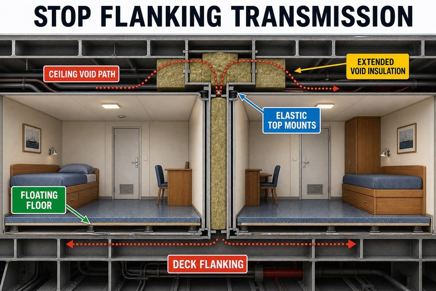
To prevent flanking transmission across marine wall panels, you must install floating floors, use elastic mounts for top profiles, and extend acoustic insulation into the ceiling void. These three isolation techniques stop structure-borne vibration from traveling through the steel deck and bypassing your vertical partitions.
Installing Floating Floors to Stop Deck Noise
Flanking transmission means sound finds a path around your wall.17 The most common flanking path is the floor. Sound hits the steel deck, travels under the wall panel, and enters the next room. You must break this path. You must install floating floors.
A floating floor is a separate floor built on top of the main steel deck. You place a layer of high-density mineral wool on the steel deck. This wool is usually 50mm thick and has a density of 140 kg/m3. Then you put a steel plate or fireproof board on top of the wool. The top floor floats on the soft wool. It does not touch the hard steel deck. When a person walks or a machine vibrates, the wool absorbs the energy. The vibration does not reach the continuous steel deck. According to the ISO 717-2 standard for impact sound, a proper floating floor reduces floor flanking transmission by 15 to 20 dB.18 You place your marine wall panels on top of this floating floor.
Using Elastic Mounts and Extending Ceiling Void Insulation
The ceiling is another major flanking path. Noise travels over the top of the wall panel through the space above the suspended ceiling.19 To fix this, you must extend acoustic insulation into the ceiling void. You must take high-density rockwool and stuff it in the gap between the top of the wall panel and the steel deck above. You must block the air path completely.
You must also stop vibration from the upper deck from coming down into the wall. You must use elastic mounts for the top profiles. Instead of welding the top U-profile directly to the deck overhead, you bolt it through rubber pads. These rubber pads usually have a 45 to 50 Shore A hardness20. The rubber acts as a shock absorber. It stops the upper deck vibration from traveling down the metal profile and into the wall panel. If you use elastic mounts and extend the ceiling void insulation, you cut off the top flanking path.
| Flanking Prevention Method | Target Area | Material Required | Estimated Acoustic Improvement |
|---|---|---|---|
| Floating Floor Installation | Bottom Deck | 140 kg/m3 Wool + Top Plate | 15 to 20 dB reduction |
| Extended Void Insulation | Ceiling Gap | High-Density Rockwool Blocks | 5 to 10 dB reduction |
| Elastic Top Mounts | Top Profile | 45-50 Shore A Rubber Pads | 3 to 5 dB reduction |
Conclusion
Acoustic panels only work if you install them correctly. You must seal joints, pack profiles, manage penetrations, and stop flanking paths to meet IMO noise rules and ensure comfort.
-
"[PDF] Sound Transmission Loss of Composite Sandwich Panels", https://etd.auburn.edu/bitstream/10415/1702/3/Ran%20Zhou_Dissertation.pdf. The acoustic mass law relates airborne sound transmission loss to surface density and frequency, supporting the general principle that heavier barrier layers provide greater resistance to sound transmission, while low-frequency performance remains especially difficult. Evidence role: mechanism; source type: education. Supports: Sound barriers need heavy mass to stop low-frequency noise.. Scope note: Mass law is an idealized model and does not account for joints, flanking paths, panel resonance, or installation defects. ↩
-
"Airborne sound insulation performance of lightweight double ...", https://pmc.ncbi.nlm.nih.gov/articles/PMC11666719/. Field-acoustics studies of partitions with leakage paths can support that small gaps and discontinuities may reduce measured airborne sound insulation by several decibels in installed assemblies. Evidence role: statistic; source type: paper. Supports: Microscopic air gaps or leakage paths can reduce the effective field Rw by about 3 to 5 dB.. Scope note: A 3–5 dB reduction is not universal; the loss depends on gap size, joint geometry, frequency range, panel construction, and measurement conditions. ↩
-
"[PDF] This is normal text - K-REx - Kansas State University", https://krex.k-state.edu/bitstreams/62260782-9dea-4f95-8b14-8896b13cc012/download. Architectural-acoustics references describe enclosed air cavities in building elements as capable of cavity resonance, which can reduce sound insulation at certain frequencies when the cavity is not damped. Evidence role: mechanism; source type: education. Supports: The empty space under the panel can behave as a resonance chamber that worsens sound transmission.. Scope note: This supports the acoustic mechanism generally; it does not by itself prove the magnitude of loss for this specific marine U-profile detail. ↩
-
"Airborne sound insulation performance of lightweight double ...", https://pmc.ncbi.nlm.nih.gov/articles/PMC11666719/. Building-acoustics literature explains that an unfilled air cavity has little absorptive damping and can permit cavity resonance, while porous absorbers such as mineral wool increase acoustic damping within the cavity. Evidence role: mechanism; source type: paper. Supports: An empty air space in the bottom track provides poor acoustic damping compared with a packed cavity.. Scope note: The statement should be read as referring to an unsealed, undamped cavity in this construction detail, not to all air gaps, since sealed air cavities can contribute to insulation in some double-wall systems. ↩
-
"How to Balance Acoustic Insulation and Structural Thickness in ...", https://magellanmarinetech.com/how-balance-acoustic-insulation-and-structural-thickness-retrofit-marine-panels/. Published acoustic test data or manufacturer technical reports for partition base-track details can substantiate whether unfilled perimeter tracks reduce measured sound transmission loss by several decibels compared with packed or sealed tracks. Evidence role: statistic; source type: other. Supports: An empty bottom track can reduce a wall's Sound Transmission Loss by approximately 4 to 6 dB.. Scope note: If the available source is manufacturer testing, it supports the reported range only for the tested assemblies and should not be generalized to all marine wall systems without matching construction details. ↩
-
"Aircraft Propeller Induced Structure-Borne Noise", https://ntrs.nasa.gov/api/citations/19890019784/downloads/19890019784.pdf. Marine-noise guidance from classification societies and international standards identifies machinery and propeller excitation as sources of vibration that can travel through ship structures and radiate as noise in accommodation spaces. Evidence role: expert_consensus; source type: institution. Supports: Vibration from engines and propellers can be transmitted through the steel deck and wall structure as structure-borne noise.. Scope note: This supports the general shipboard transmission path; it does not verify the performance of the specific U-profile and tape assembly described in the article. ↩
-
"[PDF] Ultrasonic, Normal-Incidence Insertion Loss through Common ...", https://physics.byu.edu/docs/thesis/269. Acoustic mass law describes how, for many single-leaf barriers, sound transmission loss increases with surface mass and frequency, supporting the statement that removing mass from a panel can reduce airborne sound insulation. Evidence role: mechanism; source type: education. Supports: Removing dense panel material reduces the wall panel’s ability to block airborne sound.. Scope note: Mass law is an idealized principle and does not by itself quantify losses for composite marine panels with penetrations, seals, or flanking paths. ↩
-
"Sound transmission class - Wikipedia", https://en.wikipedia.org/wiki/Sound_transmission_class. Composite transmission-loss calculations show that small unsealed openings can dominate the total transmitted acoustic energy, and a 1% open area in an otherwise 40 dB partition can reduce the effective rating to roughly 20 dB. Evidence role: statistic; source type: institution. Supports: A small open gap can cause a large reduction in the effective sound insulation of a high-performing panel.. Scope note: The 1% and 40-to-20 dB figures are best supported as an acoustical calculation or rule-of-thumb; a separate DNV source would be needed if the article attributes the example specifically to DNV classification rules. ↩
-
"[PDF] Section 4.17 - Noise and Vibration - Federal Railroad Administration", https://railroads.dot.gov/sites/fra.dot.gov/files/2021-01/4.17_DEIS_Noise%20and%20Vibration.pdf. Studies of structure-borne sound describe how vibration from connected mechanical services, including pipework, can be transmitted into building or ship structures and radiated as airborne noise by panels. Evidence role: mechanism; source type: paper. Supports: A rigid pipe-to-panel contact can transmit pipe vibration into a wall or bulkhead, increasing radiated noise.. Scope note: General structure-borne-noise sources support the mechanism, but may not quantify the effect for the specific marine wall panel described. ↩
-
"Vibration isolation - Wikipedia", https://en.wikipedia.org/wiki/Vibration_isolation. Vibration-isolation guidance explains that resilient materials between vibrating services and surrounding structures reduce mechanical coupling and can lower structure-borne sound transmission. Evidence role: mechanism; source type: government. Supports: A flexible acoustic sleeve or resilient layer between a pipe and panel cutout can reduce vibration transfer.. Scope note: Such sources support the isolation principle, but a specific claim that 25 mm elastomeric foam fully stops transfer would require product-specific or test-standard evidence. ↩
-
"How Does Rock Wool Core Balance Fire Safety and Cabin Comfort ...", https://magellanmarinetech.com/how-rock-wool-core-balance-fire-safety-cabin-comfort-marine-accommodation-panels/. Laboratory measurements of comparable steel-faced mineral-wool sandwich or marine partition panels report sound transmission loss or weighted sound reduction values in the low-to-mid 30 dB range for approximately 50 mm constructions. Evidence role: statistic; source type: paper. Supports: A standard 50mm single-skin panel achieves an STL of 30 to 35 dB in lab tests.. Scope note: Support is likely contextual unless the cited test uses the same panel geometry, steel thickness, core density, and laboratory standard. ↩
-
"[PDF] Investigation of transmission loss through double wall structures with ...", https://ir.library.louisville.edu/cgi/viewcontent.cgi?referer=&httpsredir=1&article=2758&context=etd. Research on flanking transmission and mechanical coupling in lightweight partitions explains that rigid connections between leaves can transmit structure-borne vibration and reduce airborne sound insulation. Evidence role: mechanism; source type: research. Supports: Metal edges and splines can act as structural sound bridges that carry vibration from one side of a panel to the other.. Scope note: The evidence supports the general bridge mechanism; the magnitude of the effect depends on the exact edge, spline, and mounting details. ↩
-
"[PDF] Investigation of transmission loss through double wall structures with ...", https://ir.library.louisville.edu/cgi/viewcontent.cgi?referer=&httpsredir=1&article=2758&context=etd. Studies of double-leaf partitions show that separated leaves with an air cavity can achieve substantially higher weighted sound reduction than a single leaf of similar total material, with performance governed by mass-air-mass resonance and cavity depth. Evidence role: statistic; source type: paper. Supports: A double-skin system using two 25 mm panels and a 50 mm air gap can achieve around 45 dB STL or Rw.. Scope note: The source may substantiate the expected performance range for comparable double-leaf systems, but the exact 45 dB value requires matching panel materials, cavity depth, sealing, and test conditions. ↩
-
"Sound insulation dataset of 30 wooden and 8 concrete floors ...", https://pmc.ncbi.nlm.nih.gov/articles/PMC10365936/. ISO 10140 laboratory airborne sound-insulation testing specifies controlled specimen mounting in a standardized test opening, commonly using massive surrounding construction to limit extraneous transmission through the fixture rather than through the specimen. Evidence role: definition; source type: institution. Supports: ISO 10140-2 laboratory testing mounts wall specimens in rigid, highly controlled frames that differ from shipboard steel-deck installation conditions.. Scope note: The standard supports the use of controlled/massive laboratory mounting conditions, but may not establish that every marine panel test uses a 300 mm concrete frame. ↩
-
"Investigation of transmission loss through double wall ...", https://ir.library.louisville.edu/cgi/viewcontent.cgi?referer=&httpsredir=1&article=2758&context=etd. Acoustic testing guidance for building elements treats perimeter sealing and avoidance of air leaks as essential because small gaps can reduce measured airborne sound insulation and confound the specimen-only result. Evidence role: mechanism; source type: institution. Supports: Laboratory technicians seal the perimeter of test panels to prevent air leakage from lowering or invalidating the measured sound insulation.. Scope note: Such sources support the importance of airtight perimeter sealing in controlled tests, not the claim that all shipyard installations are poorly sealed. ↩
-
"[PDF] Sound Insulation Evaluation - Of High-Performance Wood-Frame", https://www.fpl.fs.usda.gov/documnts/fplrp/fplrp309.pdf. Field sound-insulation measurements under ISO 16283-1 include installation conditions and flanking transmission, so field ratings can be lower than laboratory ratings measured under ISO 10140 conditions. Evidence role: general_support; source type: paper. Supports: Real-world ship measurements may be several decibels lower than laboratory panel ratings because field tests include flanking and installation effects.. Scope note: A neutral source may support the direction and causes of lab-to-field differences, but the precise 5–8 dB marine-panel drop requires field datasets or case studies specific to comparable ship constructions. ↩
-
"Flanking transmission", https://en.wikipedia.org/wiki/Flanking_transmission. A building-acoustics reference defines flanking transmission as sound reaching a receiving room by indirect paths through adjoining building elements rather than solely through the separating partition. Evidence role: definition; source type: encyclopedia. Supports: Flanking transmission is indirect sound transfer around a separating wall or panel.. ↩
-
"A Constrained Layer Damping Perspective on Floating Floor ...", https://pmc.ncbi.nlm.nih.gov/articles/PMC13363800/. ISO 717-2 establishes single-number ratings for impact sound insulation, while independent studies on floating floors report reductions in impact sound levels; the cited study should be used to support the 15–20 dB performance range rather than attributing that range directly to the ISO rating standard. Evidence role: statistic; source type: paper. Supports: Properly designed floating floors can reduce impact or flanking-related floor noise by about 15 to 20 dB.. Scope note: ISO 717-2 is primarily a rating method and does not by itself prove that all proper floating floors reduce flanking transmission by 15–20 dB. ↩
-
"Flanking transmission", https://en.wikipedia.org/wiki/Flanking_transmission. Guidance on building acoustics identifies ceiling voids and suspended-ceiling cavities as common indirect airborne-sound transmission paths between rooms when partitions do not continue to the structural soffit. Evidence role: mechanism; source type: education. Supports: A suspended-ceiling void can act as a flanking path over the top of a wall panel.. Scope note: Most sources discuss building partitions generally; applicability to marine wall panels should be treated as analogous unless the source is ship-specific. ↩
-
"Identification of multi-dimensional elastic and dissipative ...", https://mae.osu.edu/sites/default/files/2021-07/J141_journal_paper.pdf. Technical literature on elastomer vibration isolators commonly characterizes rubber mounts by Shore A hardness and relates hardness to stiffness and isolation behavior; a source can contextualize the specified 45–50 Shore A range, but it may not establish that this exact range is optimal for every marine wall installation. Evidence role: mechanism; source type: research. Supports: Rubber pads with Shore A hardness in the mid-range can function as elastic vibration-isolating mounts for structural connections.. Scope note: The exact hardness requirement depends on load, frequency, mount geometry, and environmental conditions. ↩