
Ship noise ruins passenger comfort. Ignoring airborne or structure-borne paths leads to sea trial failures. Here is how to ensure your panel supplier understands both.
To verify a supplier understands both marine noise paths, you must assess their grasp of airborne sound reduction and structure-borne vibration isolation. A qualified supplier will provide comprehensive low-frequency test data, specific structural damping metrics, and detailed installation drawings showing resilient mounts to ensure full sea trial compliance.
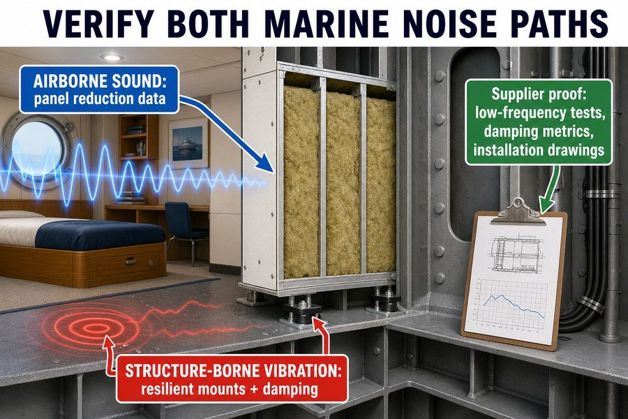
Let's break down exactly how you can test their knowledge before signing any purchase orders.
What Questions Reveal If a Marine Interior Panel Supplier Understands Structure-Borne Vibration?
Buying cheap panels often means hidden vibration issues. If your supplier only talks about airborne noise, your cabins will shake. Ask these specific questions to expose their actual expertise.
To reveal if a marine panel supplier understands structure-borne vibration, ask three specific questions: How do your panels isolate low-frequency engine vibrations below 100 Hz? What is the dynamic stiffness of your resilient mounts? And can you provide insertion loss data for the complete assembled panel system?

At Magellan Marine, I talk to many buyers who just ask for a panel's price and fire rating. But if you do not ask about vibration, you will fail the acoustic tests. You must ask the three questions mentioned above. Let us look at why these questions matter and what answers you should expect.
Question 1: Isolating Low-Frequency Engine Vibrations Below 100 Hz
Large marine diesel engines create heavy vibrations. These vibrations travel through the steel hull. They usually happen at low frequencies, between 10 Hz and 50 Hz1. If you ask a supplier how they stop low-frequency noise, a bad supplier will just point to their rock wool density. Rock wool only stops airborne noise2. A good supplier will explain how they use constrained layer damping and flexible mounting tracks3 to stop the steel from shaking the panel.
Question 2: Determining the Dynamic Stiffness of Resilient Mounts
You cannot attach a rigid wall panel directly to a shaking steel deck. You need rubber or spring mounts. The key metric here is "dynamic stiffness," measured in Meganewtons per meter (MN/m). I always ask suppliers for this number. If they do not know it, they do not understand marine noise. For floating floors or ceiling hangers on a ship, you want a dynamic stiffness of 10 to 20 MN/m. Lower numbers mean softer mounts, which block vibration better.4
Question 3: Requesting Insertion Loss Data for the Complete Assembled Panel System
Many factories only test one flat panel. But a ship cabin has corners, doors, and profiles. You must ask for the insertion loss data of the complete system. Insertion loss shows how much noise drops when the whole system is built. It proves the connection joints do not leak vibration.
| Supplier Evaluation Question | Bad Supplier Answer | Good Supplier Answer (Target Values) |
|---|---|---|
| How do you stop vibrations below 100 Hz? | "Our panels are thick." | "We use damping plates and elastic profiles." |
| What is the dynamic stiffness of your mounts? | "We use good rubber." | "Our rubber isolators are rated at 15 MN/m." |
| Do you have system insertion loss data? | "Here is the single panel test." | "Here is the lab report for the full assembled room." |
How to Verify a Marine Accommodation Panel Datasheet Fits Actual Ship Engine Noise?
Standard datasheets highlight high-frequency noise blocking. But your ship's main engines produce low-frequency rumbles. Here is how to read the datasheet to match real engine frequencies.
Verify a marine panel datasheet fits actual ship engine noise by checking three critical metrics: the sound reduction index at the 63 Hz and 125 Hz bands, the use of Ctr spectrum adaptation terms for low-frequency noise, and a structural damping loss factor exceeding 0.1.
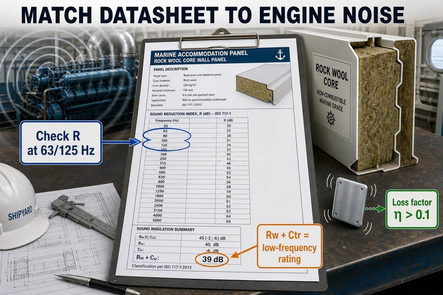
Many buyers look at a datasheet and only read the big "Rw 45 dB" number. This is a mistake. The Rw number is an average. It does not tell you if the panel will stop the deep rumble of a marine engine. I always teach my clients to look deeper into the test report to find three specific metrics.
Checking Sound Reduction Index (R) at the 63 Hz and 125 Hz Bands
Marine engines and propellers create noise in the 63 Hz and 125 Hz frequency bands.5 The IMO MSC.337(91) code sets strict limits for cabin noise. To meet these limits, you must look at the raw data table on the datasheet. Ignore the 1000 Hz or 2000 Hz numbers. Look directly at the 63 Hz and 125 Hz rows. A high-quality marine wall panel should show a sound reduction index (R) of at least 25 to 30 dB at the 125 Hz band.
Applying Ctr Spectrum Adaptation Terms for Low-Frequency Noise
Sometimes, a datasheet will show an "Rw + Ctr" value. According to ISO 717-1, Ctr is a correction factor. It adjusts the score for low-frequency urban traffic or engine noise. If a panel has an Rw of 45 dB, but the Ctr is -8, the actual performance against engine noise is only 37 dB. Always verify the Rw + Ctr value matches your shipyard's requirements.
Evaluating the Structural Damping Loss Factor Exceeding 0.1
When noise hits a metal panel, the metal rings like a bell. This is structure-borne noise turning into airborne noise. The datasheet should list a structural damping loss factor (η). This number tells you how fast the panel stops ringing. Bare steel has a loss factor of 0.001.6 A good acoustic marine panel will have a loss factor exceeding 0.1.
| Critical Datasheet Metric | What It Measures | Target Value for Marine Engines |
|---|---|---|
| Sound Reduction Index at 125 Hz | Blocking low-frequency engine rumble | 25 dB to 30 dB minimum |
| Rw + Ctr Value | Adjusted average for low-frequency noise | Depends on spec, usually > 40 dB |
| Damping Loss Factor (η) | Ability to stop metal from ringing | Greater than 0.1 |
Why Do Generic Rw Lab Reports Fail to Guarantee Structure-Borne Noise Performance on Ships?
A high Rw rating looks great on paper. Yet, cabins still fail noise tests at sea. This happens because generic lab tests ignore the real physical conditions of a moving ship.
Generic Rw lab reports fail to guarantee structure-borne noise performance because they only measure airborne sound transmission in isolated concrete chambers. These tests completely ignore the ship's steel hull flanking transmission, dynamic engine vibrations, and the critical mechanical connections between the panels and the steel deck.
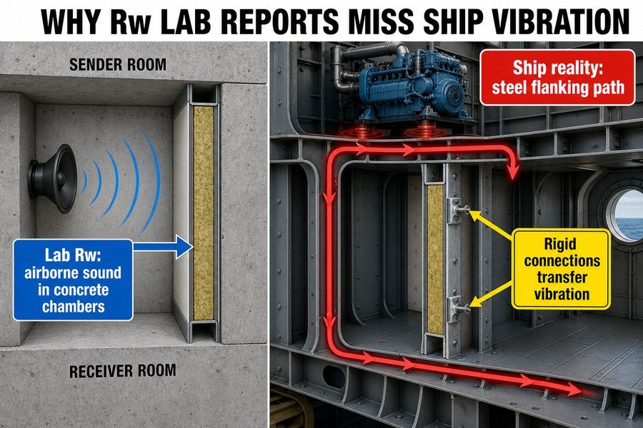
A lab report is just a piece of paper. It shows how a panel performs in a perfect room. But a ship is not a perfect room. A ship is a giant steel box vibrating in the ocean. Relying only on a generic airborne lab report is the most common reason I see projects fail their sea trials. We need to understand the three things these lab tests miss.
The Limitation of Airborne Sound Transmission Testing in Concrete Chambers
When a lab tests a panel for an Rw rating under ISO 10140-27, they build the panel between two very thick concrete rooms. The concrete does not shake. The lab only measures airborne sound—noise traveling through the air. The test does not measure structure-borne noise at all. But on a ship, the main noise comes from the steel deck vibrating beneath your feet. The lab report cannot tell you how the panel reacts to a shaking floor.
The Impact of Steel Hull Flanking Transmission
Flanking transmission happens when sound takes a detour. In a lab, sound can only go through the panel. On a ship, sound travels down the steel bulkhead, along the steel deck, and up into the next cabin. It completely bypasses your expensive wall panel. A generic lab report ignores this steel flanking path.
Overlooking Dynamic Engine Vibrations and Mechanical Connections
In a lab, the panel is sealed tightly to the concrete with heavy putty. On a ship, the panel is screwed into steel profiles. If you use hard screws and rigid metal tracks, the engine vibration travels right into the panel. The mechanical connection ruins the acoustic performance.
| Testing Condition | Generic Lab Test (ISO 10140-2) | Actual Ship Condition |
|---|---|---|
| Supporting Structure | Heavy concrete walls | Thin, vibrating steel decks |
| Noise Source | Loudspeaker in the air | Diesel engine shaking the hull |
| Flanking Paths | Blocked by lab design | High risk through steel floors and ceilings |
| Panel Connections | Sealed with acoustic putty | Screwed to metal U-profiles |
Which Drawings Prove a Marine Accommodation Panel System Addresses Structure-Borne Noise?
Sales pitches do not block noise; correct physical installation does. If your supplier cannot show you the right drawings, they do not understand how to stop structural vibrations.
To prove a marine panel system addresses structure-borne noise, suppliers must provide three specific drawings: the floating floor transition detail, the elastic ceiling hanger connection diagram, and the resilient bulkhead mounting profile showing heavy-duty rubber isolators of at least 5mm thickness separating the steel structure from the panels.
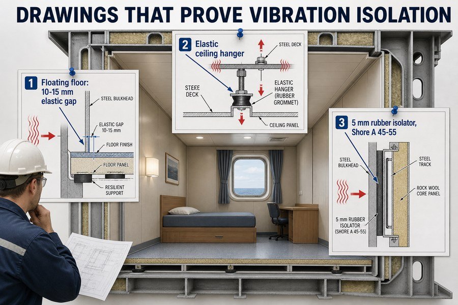
I always tell buyers to stop looking at glossy brochures and start looking at AutoCAD drawings. You can easily spot a bad supplier by checking their connection details. If they show metal touching metal, you will have a noise problem.8 You must ask for and review these three specific structural drawings.
Reviewing the Floating Floor Transition Detail Drawing
A floating floor sits on top of mineral wool to absorb vibration. But the edge of the floor must never touch the steel wall. If it touches, vibration enters the floor. The transition detail drawing must show a clear gap between the floor and the wall. This gap should be 10 to 15 millimeters wide.9 The drawing must also show this gap filled with a flexible acoustic sealant, not hard cement.
Examining the Elastic Ceiling Hanger Connection Diagram
Your marine ceiling hangs from the steel deck above. If the supplier provides rigid metal brackets, the deck vibration will turn the ceiling into a giant speaker. The ceiling hanger diagram must show elastic elements. Look for rubber grommets or small steel springs inside the hanger bracket. These elastic parts act like shock absorbers for the ceiling panels.
Verifying the Resilient Bulkhead Mounting Profile with 5mm Rubber Isolators
Wall panels sit inside metal U-profiles on the floor and ceiling. The drawing for this profile must show rubber isolators. The steel panel cannot sit directly on the steel profile. The drawing should specify a heavy-duty rubber pad. According to marine standards, this rubber isolator must have a minimum thickness of 5mm and a Shore A hardness of 45 to 5510 to effectively block structure-borne noise.
| Required Acoustic Drawing | What to Look For | Red Flag (Do Not Buy) |
|---|---|---|
| Floating Floor Transition Detail | 10-15mm gap with flexible sealant | Floor edge touching the steel wall |
| Elastic Ceiling Hanger Diagram | Rubber grommets or spring mounts | Rigid Z-profiles bolted directly to steel |
| Resilient Bulkhead Mounting Profile | 5mm rubber isolator pads (Shore A 45-55) | Wall panel sitting on bare metal track |
What Acoustic Specification Errors for Marine Interior Panels Cause Sea Trial Non-Compliance?
One wrong line in your purchasing contract can ruin the whole project. Many buyers copy old specifications, leading to disastrous noise test failures during the final sea trials.
Three acoustic specification errors cause sea trial non-compliance: specifying single-number Rw ratings without low-frequency requirements, failing to define a maximum dynamic stiffness for resilient mounts below 15 MN/m, and ignoring flanking paths by not mandating elastic sealants for all panel joints and penetrations.
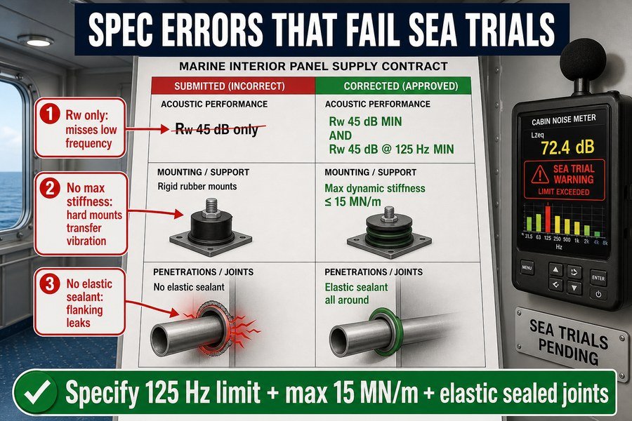
When you write a purchase order for a marine interior company, you must be very precise. A vague specification gives the factory permission to use cheap materials. In my experience, sea trial failures almost always trace back to a poorly written spec sheet. If you want to pass the noise tests, you must avoid these three common errors.
Specifying Single-Number Rw Ratings Without Low-Frequency Requirements
The biggest mistake is writing "Wall panel must be Rw 45 dB." As we discussed earlier, this ignores engine noise11. When you write your specification, you must include the low-frequency limit. You should write: "Wall panel must achieve Rw 45 dB, and the sound reduction index at 125 Hz must not be less than 28 dB12." This forces the supplier to provide heavy, damped panels instead of light, hollow ones.
Failing to Define a Maximum Dynamic Stiffness for Resilient Mounts Below 15 MN/m
If you just write "include rubber mounts," the supplier will buy the cheapest, hardest rubber available. Hard rubber transfers vibration like solid steel.13 You must control the quality of the rubber in your contract. Your specification must state: "All resilient mounts and ceiling hangers must have a maximum dynamic stiffness of 15 MN/m." This guarantees you get soft, effective isolators.
Ignoring Flanking Paths by Not Mandating Elastic Sealants
When cables or pipes pass through a wall panel, they create a hole. If the shipyard fills this hole with hard fire-putty, it creates a bridge for structure-borne noise14. Your specification must address flanking paths. You must write: "All panel joints and penetrations must be sealed with a non-hardening, acoustic elastic sealant with a minimum density of 1.3 g/cm3."
| Common Specification Error | Bad Contract Wording | Correct Contract Wording |
|---|---|---|
| Ignoring Low Frequencies | "Provide Rw 45 dB panel." | "Provide Rw 45 dB panel, minimum 28 dB at 125 Hz." |
| No Stiffness Limit | "Supply rubber base profiles." | "Supply resilient profiles with max dynamic stiffness of 15 MN/m." |
| Ignoring Flanking Paths | "Seal all wall penetrations." | "Seal all penetrations with acoustic elastic sealant (density > 1.3 g/cm3)." |
Conclusion
Verifying your supplier understands both airborne and structure-borne noise prevents costly sea trial failures. Always demand low-frequency data, detailed isolation drawings, and specific dynamic stiffness values before buying your marine panels.
-
"Optimisation of a resonance changer to minimise the vibration ...", https://ui.adsabs.harvard.edu/abs/2007JSV...300..101D/abstract. Studies of shipboard diesel-engine and hull vibration identify dominant excitation components in the low-frequency range associated with engine firing orders, shaft rotation, and structural transmission; this supports treating 10–50 Hz vibration as a relevant design concern for marine interiors. Evidence role: general_support; source type: paper. Supports: Large marine diesel engines commonly generate low-frequency vibrations that can transmit through the steel hull, often in the 10–50 Hz range.. Scope note: The exact frequency range varies with engine speed, mounting arrangement, propeller/shaft system, and hull structure, so the source would contextualize rather than prove a universal 10–50 Hz range. ↩
-
"Use of Different Textile Structures as Acoustic Materials", https://www.academia.edu/90668482/Use_of_Different_Textile_Structures_as_Acoustic_Materials. Acoustics references describe mineral wool as a porous absorber that dissipates airborne sound energy in cavities, while structure-borne vibration control typically requires isolation, damping, or resilient connections; this supports the distinction between airborne absorption and vibration isolation. Evidence role: mechanism; source type: education. Supports: Rock wool is mainly useful for airborne sound absorption and is not sufficient by itself to control low-frequency structure-borne vibration.. Scope note: The word “only” is stronger than most technical sources would state, because mineral wool can influence coupled constructions, but it is not by itself a primary treatment for low-frequency structure-borne vibration. ↩
-
"Vibro-acoustical analysis and design of a multiple-layer ...", https://digitalcommons.mtu.edu/cgi/viewcontent.cgi?article=1382&context=etds. Vibration-control literature explains that constrained-layer damping converts flexural vibration energy into heat through shear deformation in a viscoelastic layer, while resilient mounts reduce vibration transmission by mechanically decoupling connected structures. Evidence role: mechanism; source type: research. Supports: Constrained layer damping and flexible mounting tracks can reduce the transmission of structure-borne vibration into marine interior panels.. Scope note: Such sources establish the physical mechanisms, but they do not verify that any particular supplier’s panel system achieves the claimed performance without system-specific testing. ↩
-
"Study on Dynamic Characteristics of Resilient Mount Under ...", https://pmc.ncbi.nlm.nih.gov/articles/PMC11509879/. Standards and vibration-isolation texts define dynamic stiffness as the force-to-displacement response of a resilient element under dynamic loading and show that lower stiffness generally lowers the natural frequency of an isolated system, improving isolation above resonance. Evidence role: mechanism; source type: institution. Supports: Dynamic stiffness is a key property of resilient mounts, and lower dynamic stiffness generally improves vibration isolation when the system is designed to operate above resonance.. Scope note: Neutral sources can support the stiffness-isolation relationship, but the specific 10–20 MN/m design target is application-dependent and would require a marine-specific standard, laboratory report, or engineering design guide to substantiate directly. ↩
-
"How Should Engineers Evaluate a Marine Accommodation Panel STL ...", https://magellanmarinetech.com/how-engineers-evaluate-marine-accommodation-panel-stl-frequency-curve/. A peer-reviewed ship-noise or marine-engine acoustics source can document that propulsion machinery and propellers often generate strong low-frequency components, supporting the need to examine octave-band performance around 63 Hz and 125 Hz. Evidence role: general_support; source type: paper. Supports: Marine engines and propellers create noise in the 63 Hz and 125 Hz frequency bands.. Scope note: The exact dominant frequencies vary with engine type, rpm, hull structure, mounting, and measurement location. ↩
-
"Evaluation of Loss Factor Estimation Techniques ... - KU ScholarWorks", https://kuscholarworks.ku.edu/bitstreams/29602666-f613-45a2-b23b-99d32f8d5c03/download. Engineering acoustics and vibration references commonly report untreated steel or similar structural metals as having very low material damping, with loss factors on the order of 10^-3, supporting the statement that bare steel rings readily without added damping. Evidence role: statistic; source type: education. Supports: Bare steel has a structural damping loss factor of about 0.001.. Scope note: Published loss-factor values depend on alloy, frequency, temperature, specimen geometry, and boundary conditions, so 0.001 should be treated as an approximate order-of-magnitude value. ↩
-
"Sound insulation dataset of 30 wooden and 8 concrete floors ...", https://pmc.ncbi.nlm.nih.gov/articles/PMC10365936/. ISO 10140-2 defines a laboratory method for measuring airborne sound insulation of building elements, so an Rw value derived from this framework characterizes standardized airborne transmission rather than structure-borne vibration in service. Evidence role: definition; source type: institution. Supports: ISO 10140-2 laboratory testing measures airborne sound insulation and does not evaluate structure-borne noise from vibrating ship structures.. Scope note: This supports the scope of the laboratory test but does not by itself prove how any specific shipboard installation will perform. ↩
-
"[PDF] Analysis And Experimental Validation Of Structure-Borne Noise From ...", https://docs.lib.purdue.edu/cgi/viewcontent.cgi?article=3275&context=icec. The source explains that rigid structural connections can transmit structure-borne vibration and create flanking noise paths, supporting the concern about metal-to-metal contact in acoustic assemblies. Evidence role: mechanism; source type: education. Supports: Metal-to-metal structural contact can transmit vibration and contribute to noise problems.. Scope note: This supports the physical mechanism generally; it may not prove that every metal-to-metal detail will cause an audible problem in every vessel. ↩
-
"Design and Testing of Modular Expansion Joint Noise ...", https://depts.washington.edu/trac/bulkdisk/pdf/920.1.pdf. The source identifies perimeter isolation gaps in floating-floor systems as a standard method for preventing rigid contact with adjacent walls and preserving acoustic separation; if it specifies dimensions, it can contextualize the stated 10–15 mm range. Evidence role: expert_consensus; source type: institution. Supports: A floating-floor transition should include a perimeter gap, and the article specifies a 10–15 mm width.. Scope note: Many sources support the need for a perimeter gap, but the exact 10–15 mm range may vary by system, material, and manufacturer specification. ↩
-
"Why Do Marine Accommodation Panels Perform Differently in Labs ...", https://magellanmarinetech.com/why-marine-accommodation-panels-perform-differently-in-labs-versus-onboard/. The source states the applicable marine, classification-society, or ship-accommodation requirement for rubber isolator thickness and Shore A hardness, supporting the specified 5 mm and 45–55 Shore A values if those limits are codified. Evidence role: expert_consensus; source type: institution. Supports: Marine standards require or commonly specify 5 mm rubber isolators with Shore A hardness of 45–55 for resilient bulkhead mounting.. Scope note: If no single marine standard gives these exact values, the citation would only support them as a common specification rather than a mandatory standard. ↩
-
"Analysis between weighted sound reduction index according to ISO ...", https://www.academia.edu/21437199/Analysis_between_weighted_sound_reduction_index_according_to_ISO_717_1_and_indices_according_to_ISO_16717_1. Standards and acoustics literature describe Rw as a single-number weighted sound reduction rating, while marine diesel and machinery noise often contains important low-frequency components; this supports the concern that an Rw value alone may not characterize engine-noise insulation adequately. Evidence role: mechanism; source type: institution. Supports: Specifying only an Rw rating can overlook low-frequency engine-noise performance.. Scope note: This would support the acoustic rationale generally, but it would not by itself prove that every Rw 45 dB panel fails for engine noise. ↩
-
"How to choose the right marine wall panels for marine interior projects?", https://magellanmarinetech.com/how-choose-right-marine-wall-panels-for-marine-interior-projects/. Laboratory sound-insulation standards report sound reduction index values by frequency band, including low-frequency one-third-octave bands such as 125 Hz; this supports using a band-specific requirement alongside Rw for low-frequency control. Evidence role: definition; source type: institution. Supports: A marine wall-panel specification can require a minimum sound reduction index at 125 Hz in addition to Rw.. Scope note: A standards source can justify specifying a 125 Hz band value, but a project-specific source would be needed to validate the exact 28 dB threshold for a given vessel or panel system. ↩
-
"Study on Dynamic Characteristics of Resilient Mount Under ...", https://pmc.ncbi.nlm.nih.gov/articles/PMC11509879/. Vibration-isolation theory shows that higher mount stiffness increases transmitted force above the isolation frequency, so a hard rubber mount can provide poor isolation compared with a softer resilient mount. Evidence role: mechanism; source type: education. Supports: Harder, stiffer rubber mounts transmit more vibration and are less effective as isolators.. Scope note: The source would support the stiffness-transmission mechanism, but the comparison with solid steel is rhetorical rather than a literal equivalence. ↩
-
"Flanking transmission - Wikipedia", https://en.wikipedia.org/wiki/Flanking_transmission. Building and shipboard acoustics sources describe flanking transmission through rigid connections, penetrations, and service paths; this supports the claim that hard material around penetrations can bypass the main wall panel and transmit structure-borne sound. Evidence role: mechanism; source type: paper. Supports: Rigidly filled wall penetrations can create flanking paths or bridges for structure-borne noise.. Scope note: This supports the general flanking-path mechanism, but the acoustic effect of a specific fire-putty product would require product-specific or assembly test data. ↩