
Are your newly outfitted ship cabins failing sea trial noise tests? Rigidly fixing lining panels transfers engine vibrations directly into the cabin. Here is how to stop this problem.
Rigid panel fixing creates structure-borne noise problems by forming solid mechanical connections (acoustic bridges) between the vibrating steel hull and the cabin panels. To fix this, you must use resilient mounts, isolation profiles, and maintain proper clearance to block vibration transmission pathways completely.
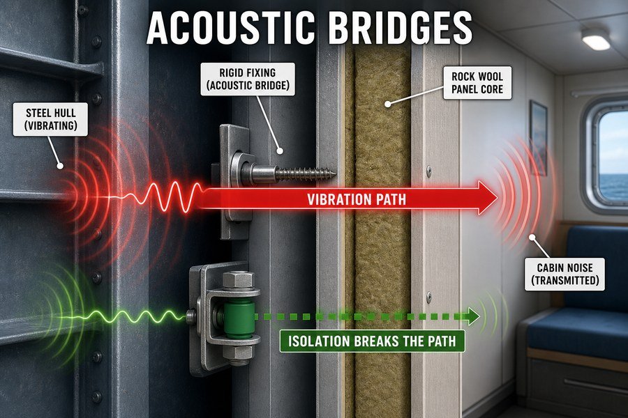
Let me break down exactly how these sound bridges form and share the specific outfitting techniques we use at Magellan Marine to stop hull vibrations from ruining your cabin acoustics.
How Does Screw-Fixing a Marine Lining Panel Create a Structure-Borne Acoustic Bridge?
Do you use standard screws to attach lining panels directly to steel frames? This common mistake turns your cabin wall into a giant speaker, amplifying engine room vibrations.
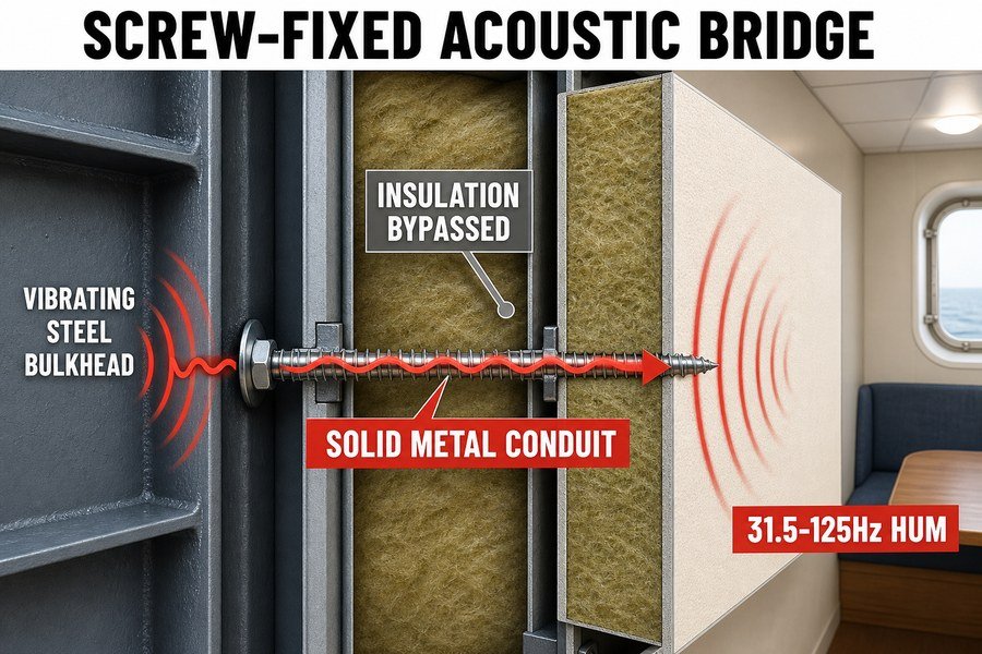
Screw-fixing creates a structure-borne acoustic bridge by acting as a solid metal conduit. Vibrations travel from the hull, through the steel screw, directly into the decorative panel. This bypasses the mineral wool insulation entirely, causing the panel to radiate low-frequency noise (typically 31.5Hz to 125Hz) into the room.
The Physical Mechanism of Screw-Fixed Acoustic Bridges
When I started out at the marine outfitting factory, I saw workers drive standard self-tapping steel screws right through decorative panels and into the steel bulkhead profiles. They thought tighter was better. But in a ship, the steel hull constantly vibrates. Ship engines and propellers generate strong low-frequency vibrations. According to the International Maritime Organization (IMO) MSC.337(91) code on noise levels, main diesel engines typically generate peak vibrational energy between 31.5Hz and 125Hz1.
When you use a steel screw, you create a direct highway for these vibrations. Steel is an excellent conductor of vibration. The vibration wave travels up the steel bulkhead, enters the steel screw, and goes right into the thin metal or composite face of the lining panel. You can pack the wall with the best A-60 marine mineral wool in the world, but it will not matter. The sound wave simply bypasses the insulation via the screw.2 The panel then acts like the cone of a stereo speaker. It vibrates and pushes the air inside the cabin, creating a low, humming noise that drives passengers crazy.
Noise Level Increases Caused by Metal Fasteners
To understand the real-world impact, we can look at standard acoustic testing. According to ISO 717-1 acoustic standards for building and marine elements, adding rigid mechanical links greatly reduces the Sound Reduction Index (Rw). A single rigid screw connection per square meter can reduce the panel's overall transmission loss by 3 to 5 decibels (dB).3 In the shipping industry, a 3 dB increase means the sound energy has doubled.
Here is a breakdown of how rigid screws impact the noise rating of a standard 50mm marine wall panel system:
| Installation Method for 50mm Panel | Structural Vibration Transfer | Estimated Sound Reduction (Rw) | Cabin Noise Result |
|---|---|---|---|
| Fully Decoupled (No direct screws) | Minimal | 44 dB | Passes standard passenger cabin limits |
| 1 Rigid Screw per Square Meter | High | 40 dB | Noticeable low-frequency hum |
| 4 Rigid Screws per Square Meter | Severe | 36 dB | Fails IMO limits (Loud rattling) |
If you want to pass shipyard inspections in Europe or the US, you must stop your installation teams from using rigid screw connections on acoustic bulkheads.
Why Are Resilient Mounts Essential for Attaching Marine Lining and Ceiling Panels to Vibrating Hulls?
If your luxury ship interior rattles during sailing, clients will complain. Without resilient mounts, every vibration from the propellers goes straight into your beautiful ceiling panels.
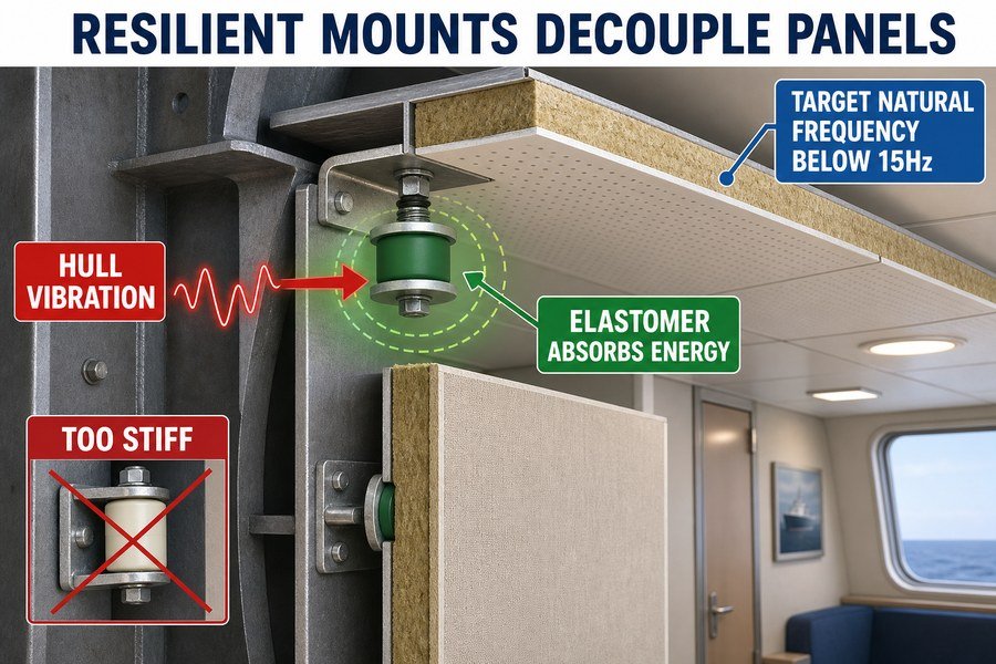
Resilient mounts are essential because they use rubber or silicone elastomers to decouple the panel from the hull. They absorb vibrational energy, lower the natural frequency of the panel system (typically below 15Hz), and prevent structure-borne noise from transferring into marine lining and ceiling panels.
How Elastomeric Resilient Mounts Decouple Panel Systems
A resilient mount works like the shock absorber on a car. Instead of bolting a panel directly to the steel frame, you place a flexible mount between them. This mount is usually made from a rubber or silicone elastomer. When the ship hull shakes, the rubber bends and compresses. It eats the vibrational energy4 before that energy can reach the decorative panel.
The most important engineering metric for these mounts is the natural frequency. To isolate noise effectively, the natural frequency of the panel-and-mount system must be significantly lower than the disturbing frequency5 of the ship's engine. A basic rule of vibration isolation is that the system's natural frequency must be less than 70% of the lowest engine frequency6. Because ship engines produce noise around 30Hz4, we aim for a mount natural frequency below 15Hz. I once worked with a client who bought cheap, hard plastic mounts to save money. The plastic was too stiff. It did not lower the natural frequency enough, and the cabin failed the 55 dB(A) noise limit required by SOLAS regulations. They had to tear down the whole ceiling and buy the correct rubber mounts.
Comparing Natural Frequencies of Marine Mount Types
You have several choices when buying resilient mounts in Asia. You must check the "Shore A" hardness rating. A softer rubber gives better acoustic results but supports less weight. You must find the right balance for your heavy marine panels.
Here is a comparison of common materials used in marine resilient mounts:
| Mount Elastomer Material | Typical Shore A Hardness | Estimated Natural Frequency | Best Marine Application |
|---|---|---|---|
| Hard Plastic (Nylon) | 80+ | 35Hz+ (Poor Isolation) | Do not use for acoustics |
| Standard EPDM Rubber | 45 to 55 | 12Hz to 15Hz | Standard cabin wall linings |
| High-Grade Silicone | 30 to 40 | 8Hz to 10Hz | Luxury cruise ceilings |
| Spring + Rubber Hybrid | N/A (Spring rate applies) | 5Hz to 7Hz | Heavy engine room acoustic cladding |
Always ask your supplier for the natural frequency data sheet before you buy mounts for a major shipyard project.
How Does Concealed Steel Contact Create Hidden Structure-Borne Noise Paths Behind Marine Lining Panels?
Think your panels are fully isolated? Hidden steel-to-steel contact behind the walls often destroys your acoustic plan. Finding these hidden noise paths after installation is very expensive.
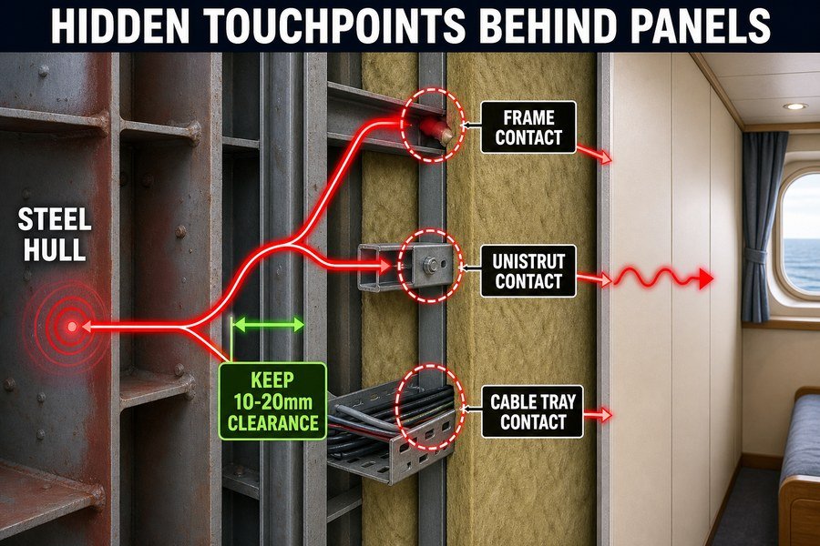
Concealed steel contact creates hidden structure-borne noise paths when internal framework, unistruts, or cable trays touch the back of the lining panel. These three hidden touchpoints allow vibrations to bypass resilient mounts, transferring structural energy directly to the cabin interior and ruining acoustic performance.
Internal Framework and Unistrut Contact Issues
When I inspect a noisy cabin, I rarely look at the front of the panel first. I always look behind it. Ship interiors have limited space. Electricians, plumbers, and panel installers all fight for the same few inches of space behind the decorative wall. The first two major culprits are internal steel frameworks and unistruts. Unistruts are metal framing systems used to hold pipes and heavy equipment.
Installers often push the marine lining panel back so far that the metal back of the panel physically rests against a steel unistrut or a structural stiffener. Even if you used the best resilient mounts on the edges, this middle contact point ruins everything. It creates a direct, rigid acoustic bridge.7 European shipyard guidelines typically require a minimum clearance gap of 10mm to 15mm between the back of any acoustic panel and any structural steel frame.8 If the ship rolls and the panel flexes, it still must not touch the steel behind it.
Cable Tray Vibrations Behind Marine Panels
The third hidden touchpoint is the electrical cable tray. Cable trays hold thick, heavy bundles of power lines. On many ships, these trays are bolted straight to the vibrating hull. They carry the hull's vibration perfectly.9
Sometimes, an electrician leaves a tray hanging loosely, or a heavy cable bundle sags over time. The tray or the cables rest against the back of the ceiling or wall panel. This transfers the vibration right into the cabin. To prevent this, you must secure all cables tightly and use damping pads if close contact is unavoidable.
Here is an inspection checklist you can use to prevent these three hidden touchpoints:
| Component Behind Panel | Required Clearance | Prevention Method | Acoustic Risk Level |
|---|---|---|---|
| Structural Framework | Minimum 15mm | Measure gap before final locking | Very High |
| Metal Unistruts | Minimum 10mm | Apply 5mm neoprene foam pad to face of strut just in case | High |
| Cable Trays / Wires | Minimum 20mm | Tie-wrap all cables tightly; ensure trays do not sag | Medium to High |
Why Does Rigid Installation of Marine Lining Panels Amplify Cabin Structure-Borne Noise?
Are your panels tightly jammed together without any gap? Rigid installation turns individual panels into one massive vibrating surface, making structure-borne noise much louder inside the cabin.
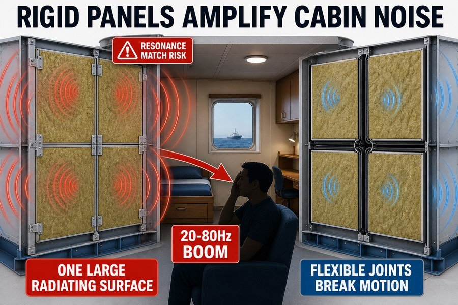
Rigid installation amplifies structure-borne noise through two mechanisms: resonance matching and increased radiating surface area. By tightly locking panels without flexible joints, the entire wall vibrates as a single large unit, pushing more air and amplifying low-frequency engine vibrations (20Hz-80Hz) into the passenger space.
The Effect of Increased Radiating Surface Area on Cabin Noise
When you install a 50mm marine sandwich panel, it has a certain surface area. Let us say it is 0.6 meters wide by 2.4 meters high. If a vibration enters this single panel, it pushes a specific amount of air. Now, imagine you take ten of these panels and lock them together tightly with rigid metal splines and no flexible sealant. You just created a single, massive rigid wall that is 6 meters long.
In acoustic science, a larger radiating surface area moves more air10. It acts just like a giant subwoofer. When a low-frequency vibration from the ship's engine hits this rigid wall, the entire 6-meter wall moves back and forth together. This amplifies the noise in the cabin significantly. By using flexible joint profiles between the panels, you break the wall into smaller independent sections. A small panel cannot radiate low-frequency sound (like 50Hz) as efficiently as a large, rigid wall can.11
Resonance Matching in Tightly Locked Panel Systems
The second mechanism is resonance matching. Every object has a natural frequency where it wants to vibrate. When you lock panels together rigidly, you change the stiffness and mass of the system. This alters the natural frequency of the entire wall.
If this new natural frequency accidentally matches the frequency of the ship's engine or propeller blade pass frequency (often between 20Hz and 80Hz), you get a phenomenon called resonance. Resonance causes the vibration amplitude to multiply wildly.12 The wall will shake violently, creating a deafening boom in the room.
Here is a theoretical comparison showing how rigid joining impacts low-frequency noise radiation:
| Wall Configuration (2.4m High) | Acoustic Behavior at Low Frequencies (50Hz) | Estimated Noise Increase |
|---|---|---|
| Single Standalone Panel (0.6m wide) | Poor radiator of low frequencies | Baseline (0 dB) |
| 4 Panels Decoupled with Rubber Splines | Acts as 4 small, independent radiators | + 1 dB |
| 4 Panels Rigidly Locked (Metal to Metal) | Acts as 1 large, highly efficient radiator | + 4 to 6 dB |
To keep noise levels low, you must tell your installation teams to use soft PVC or rubber joint profiles between panels instead of rigid metal locks.
Which Isolation Profiles Break Structure-Borne Noise Paths at Marine Bulkhead Tracks?
The bottom track of your bulkhead is where most vibrations enter. If you do not use the right isolation profiles here, the rest of your acoustic work is useless.
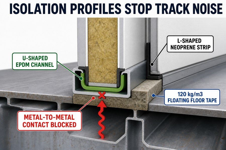
To break structure-borne noise paths at bulkhead tracks, you must use three specific isolation profiles: U-shaped EPDM rubber channels for bottom tracks, L-shaped neoprene strips for corners, and high-density mineral wool floating floor tapes. These materials stop metal-to-metal contact at the deck interface.
Applying U-Shaped EPDM Channels at Bottom Tracks
The bottom steel track (often called a U-profile) sits directly on the steel deck of the ship. The deck carries massive vibrations from the engine room below. If you put your marine panel straight into a bare steel track, you have an instant acoustic bridge13.
To break this path, we use U-shaped EPDM rubber channels. EPDM stands for Ethylene Propylene Diene Monomer. It is a tough, flexible rubber that does not degrade easily in salty sea air14. Before inserting the panel, you line the inside of the steel track with this U-shaped EPDM. I recommend a thickness of 3mm to 5mm and a Shore A hardness of around 60. This creates a soft cushion. The bottom of the panel sits on rubber, and the sides of the panel are squeezed by rubber. The panel never touches the steel track.
L-Shaped Neoprene Strips and Mineral Wool Tapes for Corner Isolation
Corners and floating floor edges are the next problem areas. When a bulkhead meets a corner pillar or a floating floor system, you need different shapes to block the noise.
First, we use L-shaped neoprene strips. Neoprene is excellent for edge isolation. You apply the L-shape to corner steel profiles so the panel edge rests against the soft strip instead of hard steel. Second, we use high-density mineral wool tapes. When building a bulkhead on top of a floating floor, you need heavy-duty isolation. We use strips of mineral wool with a density of at least 120 kg/m3. These tapes sit under the bottom track. They prevent structure-borne noise from bypassing the floating floor system15 and entering the base of the wall.
Here is a quick guide to buying these three profiles in Asia to meet US and EU standards:
| Profile Type | Material Specs | Primary Application Area | Purpose |
|---|---|---|---|
| U-Shaped Channel | EPDM, 3-5mm thick, 60 Shore A | Inside bottom steel tracks | Cradles the panel, stopping track contact |
| L-Shaped Strip | Neoprene foam, closed-cell | Corner pillars and junctions | Stops side-edge metal contact |
| Floating Floor Tape | Mineral Wool, 120 kg/m3 density | Underneath the bottom track | Isolates the track from the steel deck |
If you buy these materials from Asian suppliers, make sure they provide fire-test certificates (like MED B) because rubber and neoprene must pass low smoke and toxicity rules for marine use16.
Conclusion
Rigid fixing creates acoustic bridges that ruin cabin noise levels. By using resilient mounts, maintaining clearance, and installing proper EPDM track profiles, you can meet strict shipyard acoustic standards.
-
"Prediction of Structure-borne noise due to marine diesel engines on ...", https://www.academia.edu/16149044/Prediction_of_Structure_borne_noise_due_to_marine_diesel_engines_on_board_ships. Technical literature on ship noise and vibration commonly treats low-frequency components from main propulsion machinery and propeller excitation as important contributors to onboard vibration and structure-borne noise, including octave or one-third-octave bands in the tens to low hundreds of hertz. Evidence role: expert_consensus; source type: paper. Supports: Ship main engines and propulsion systems can generate significant low-frequency vibration in roughly the 31.5–125 Hz range.. Scope note: Such sources may support the general low-frequency range of propulsion-related vibration rather than proving the exact peak range for all main diesel engines. ↩
-
"Airborne sound insulation performance of lightweight double ...", https://pmc.ncbi.nlm.nih.gov/articles/PMC11666719/. Acoustics references on flanking transmission and sound bridges describe how rigid structural connections can transmit vibration around porous insulation or decoupled layers, reducing the acoustic isolation of lightweight partitions. Evidence role: mechanism; source type: education. Supports: A rigid screw can act as a structural sound bridge that bypasses insulation and transmits vibration into a lining panel.. Scope note: General building-acoustics evidence explains the mechanism; marine panel performance depends on the tested assembly, fastener geometry, and installation details. ↩
-
"Airborne sound insulation performance of lightweight double ...", https://pmc.ncbi.nlm.nih.gov/articles/PMC11666719/. Laboratory studies and acoustic standards on sound insulation report that small rigid connections or mechanical bridges in double-leaf or lined partitions can measurably reduce transmission loss, sometimes by several decibels depending on connection density and frequency. Evidence role: statistic; source type: paper. Supports: Rigid screw connections can reduce a panel system’s transmission loss by several decibels.. Scope note: A source may support the magnitude as assembly-dependent rather than establish a universal 3–5 dB reduction for every marine panel system. ↩
-
"Ship noise extends to frequencies used for echolocation by ... - PMC", https://pmc.ncbi.nlm.nih.gov/articles/PMC4800784/. Studies of shipboard or marine-diesel noise commonly report strong low-frequency components in octave or one-third-octave bands around 31.5 Hz, supporting the use of approximately 30 Hz as a relevant design reference for some marine noise calculations. Evidence role: general_support; source type: paper. Supports: Ship engines can produce low-frequency noise components around 30 Hz.. Scope note: Engine-noise frequencies vary with engine type, rotational speed, mounting, and measurement location; this evidence would support 30 Hz as a plausible example, not a universal ship-engine frequency. ↩ ↩
-
"Vibration isolation | Vibrations: Embry-Riddle Aeronautical ...", https://www.purdue.edu/freeform/ervibrations/chapter-v-animations/vibration-isolation/. Standard vibration-isolation theory shows that transmissibility falls below unity only when the excitation frequency is sufficiently higher than the mounted system’s natural frequency, making natural frequency a key design parameter. Evidence role: mechanism; source type: education. Supports: Effective vibration isolation requires the mounted panel system’s natural frequency to be substantially below the disturbing excitation frequency.. Scope note: The principle is general to single-degree-of-freedom isolation models; real ship panels may require more detailed modal analysis. ↩
-
"Vibration isolation | Vibrations: Embry-Riddle Aeronautical ...", https://www.purdue.edu/freeform/ervibrations/chapter-v-animations/vibration-isolation/. Vibration-isolation transmissibility equations for a lightly damped single-degree-of-freedom system indicate that isolation begins when the excitation-to-natural-frequency ratio exceeds √2, equivalent to a natural frequency below about 0.707 of the excitation frequency. Evidence role: mechanism; source type: education. Supports: A common vibration-isolation rule is that the isolator natural frequency should be less than about 70% of the lowest disturbing frequency.. Scope note: The 70% threshold is a simplified rule of thumb and does not account for damping level, multi-axis motion, or structural resonances in a full ship installation. ↩
-
"How Do Structural Connections Impact Marine Ceiling Panel ...", https://magellanmarinetech.com/how-structural-connections-impact-marine-ceiling-panel-acoustics/. A source on structure-borne sound or flanking transmission should support that rigid mechanical contact can bypass resilient isolation and transmit vibration between structures, functioning as an acoustic bridge. Evidence role: mechanism; source type: paper. Supports: A metal contact point between the back of a marine lining panel and steel framing can create a rigid acoustic bridge that undermines resilient edge mounts.. Scope note: The source may describe the physical mechanism generally rather than specifically testing marine lining panels against unistrut or stiffeners. ↩
-
"How to choose the right marine wall panels for marine interior ...", https://magellanmarinetech.com/how-choose-right-marine-wall-panels-for-marine-interior-projects/. A shipbuilding guideline, classification-society document, or marine accommodation acoustic standard should document recommended clearance between acoustic lining panels and structural steel, or otherwise establish that physical separation is required to avoid vibration bridging. Evidence role: expert_consensus; source type: institution. Supports: European shipyard guidelines typically require a 10–15 mm clearance between acoustic panel backs and structural steel frames.. Scope note: A source may confirm the need for clearance without matching the exact 10–15 mm range; if so, the article’s numerical range would still require a more specific guideline. ↩
-
"How Do Structural Connections Impact Marine Ceiling Panel ...", https://magellanmarinetech.com/how-structural-connections-impact-marine-ceiling-panel-acoustics/. A source on ship vibration or structure-borne noise should support that equipment and services rigidly attached to a vibrating hull can transmit hull vibration into connected components and accommodation structures. Evidence role: mechanism; source type: paper. Supports: Cable trays bolted directly to a vibrating hull can transmit hull vibration toward panels or other interior elements.. Scope note: The wording “perfectly” is stronger than most technical sources will support; evidence will more likely show efficient or significant transmission through rigid attachments rather than lossless transmission. ↩
-
"Vibration and acoustic radiation of elastically supported ...", https://ui.adsabs.harvard.edu/abs/1977JSV....52....1L/abstract. Structural-acoustics literature defines radiated sound power from a vibrating surface as dependent on surface area, vibration velocity, and radiation efficiency, supporting the claim that a larger coupled panel can radiate more acoustic energy into the cabin. Evidence role: mechanism; source type: paper. Supports: In acoustic science, a larger radiating surface area moves more air.. Scope note: This supports the general acoustic mechanism, not the specific magnitude of noise increase for the stated marine panel dimensions. ↩
-
"Near-field pressure, intensity, and wave-number ...", https://vtechworks.lib.vt.edu/bitstreams/ae36d871-a791-4d0e-af38-01894ab4e5c0/download. Research on finite plate sound radiation shows that radiation efficiency depends on the relationship between acoustic wavelength and panel dimensions, providing contextual support that small panels are generally inefficient low-frequency radiators compared with larger coupled surfaces. Evidence role: mechanism; source type: paper. Supports: Small panels radiate low-frequency sound less efficiently than a larger rigid wall.. Scope note: The source would support the size-frequency relationship generally; it would not by itself verify that a 0.6 m by 2.4 m panel at exactly 50 Hz behaves as described without a panel-specific calculation. ↩
-
"Measurement of damping capacity - K-REx", https://krex.k-state.edu/bitstreams/90ff4f04-e67d-4dcc-958c-f3f2dee99af5/download. Mechanical vibration texts explain that when harmonic excitation approaches a structure’s natural frequency, the dynamic amplification factor can greatly increase vibration amplitude, with damping limiting the peak response. Evidence role: mechanism; source type: education. Supports: Resonance can greatly increase vibration amplitude when excitation frequency matches a structure’s natural frequency.. Scope note: The word “wildly” is qualitative; the actual amplification depends on damping, boundary conditions, mass, stiffness, and excitation level. ↩
-
"How Does Installation Affect Marine Wall Panel STL? - Magellan ...", https://magellanmarinetech.com/how-installation-affect-marine-wall-panel-stl/. A source on structure-borne sound transmission should be cited to show that rigid mechanical connections in ship structures can transmit vibration and that resilient interlayers are commonly used to reduce such transmission. Evidence role: mechanism; source type: paper. Supports: A marine panel placed directly into a bare steel track can create a rigid path for structure-borne sound transmission.. Scope note: This would support the acoustic-bridge mechanism generally, not prove the performance of this specific bottom-track design. ↩
-
"A Review of EPDM (Ethylene Propylene Diene Monomer) Rubber ...", https://pmc.ncbi.nlm.nih.gov/articles/PMC11207359/. A polymer reference should be cited to document EPDM’s resistance to weathering, ozone, and environmental exposure; this supports its suitability for outdoor or marine-adjacent conditions. Evidence role: general_support; source type: encyclopedia. Supports: EPDM is a durable rubber that resists degradation in salty sea-air environments.. Scope note: Such a source may establish general EPDM durability rather than direct long-term performance in every marine interior application. ↩
-
"A Constrained Layer Damping Perspective on Floating Floor ...", https://pmc.ncbi.nlm.nih.gov/articles/PMC13363800/. An acoustics source on floating floors and resilient layers should be cited to show that resilient mineral-fiber layers can reduce vibration or structure-borne sound transmission through floor-wall junctions. Evidence role: mechanism; source type: paper. Supports: High-density mineral wool tapes under a bottom track can help prevent structure-borne noise from bypassing a floating floor system.. Scope note: The source may support the principle of resilient isolation but may not verify the specified 120 kg/m3 density or this exact marine bulkhead detail. ↩
-
"Which Fire Test Standards Apply to MED-Certified Marine ...", https://magellanmarinetech.com/which-fire-test-standards-apply-to-med-certified-marine-accommodation-panels/. An IMO or Marine Equipment Directive source should be cited to show that materials used in regulated marine applications may be subject to fire-test procedures addressing flame spread, smoke, and toxicity. Evidence role: expert_consensus; source type: institution. Supports: Rubber and neoprene components used in marine interiors may need fire-test certification addressing low smoke and toxicity requirements.. Scope note: The regulatory requirement depends on vessel type, flag state, installation location, and whether the product falls within the scope of the cited approval regime. ↩