
Crew members often complain about cabin noise. You buy expensive panels, but the noise stays loud. The problem is how two different noise types mix inside the cabin.
Airborne noise from voices and structure-borne vibration from engines combine in marine cabins to create complex acoustic environments. Vibrations travel through the steel deck and re-radiate as airborne sound from interior panels, meaning both transmission paths must be blocked simultaneously to achieve quiet and compliant ship accommodations.
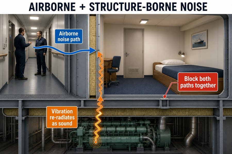
Let me explain how these two forces work together to ruin a quiet space, and what you can do about it.
Why Do Cabin Noise Complaints Persist After Installing High-Acoustic Marine Bulkhead Panels?
You spent good money on A-Class acoustic panels. Yet, the sea trial still fails the noise test. The real issue hides in how panels are installed on the deck.
Cabin noise complaints persist because high-acoustic bulkhead panels only block airborne noise, ignoring flanking paths, structural vibrations, and improper joint sealing. Sound bypasses the panels through the ceiling cavity, deck mounts, and unsealed gaps, rendering the panel's high decibel reduction rating useless against structure-borne engine frequencies.
The Impact of Flanking Paths and Structural Vibrations on Cabin Acoustics
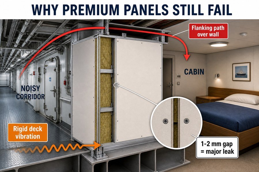
When I worked at the marine outfitting factory, I saw many buyers purchase expensive 44 dB Rw panels. But they still received complaints from shipyards in Europe and the United States. The IMO MSC.337(91) code states that standard cabin noise must not exceed 60 dB(A). If you only block direct airborne noise, you will fail this test. Airborne noise is just the sound traveling directly through the air, like people talking. But noise also finds weak spots, which we call flanking paths. A common flanking path is the open space above the ceiling panels.1 If the ceiling only provides a 25 dB reduction, engine noise travels over the high-acoustic wall and drops right down into the cabin.
At the same time, structural vibrations travel up from the main engine.2 The heavy diesel engines shake the steel hull. This shaking moves up the steel pillars and into the cabin floor. The high-acoustic panel is sitting directly on this shaking floor. The panel stops the airborne noise perfectly, but the structural vibration moves right past the thick rockwool core.
The Importance of Proper Joint Sealing in Marine Bulkhead Installations
Another big reason these panels fail is improper joint sealing. The factory tests the panels in a perfect lab with completely sealed edges. But on a real ship, installers often leave tiny gaps. Sound acts like water; it flows through any open space. If an installer leaves a 2mm unsealed gap between two acoustic panels, the overall sound reduction can drop by 10 dB.3
You must seal every single gap to stop airborne noise. Installers must use marine-grade, non-combustible acoustic sealant between the panel joints and at the deck connections. If the airborne noise finds a gap, and the structural vibrations come through the floor, the premium panels are completely wasted.
| Failure Point | Source of Noise Problem | Effect on Cabin Environment | Required Corrective Action |
|---|---|---|---|
| Flanking Paths | Open ceiling cavities and ventilation ducts | Noise bypasses the bulkhead entirely | Add acoustic baffles above the ceiling line |
| Structural Vibrations | Rigid connection to the steel ship deck | Floor vibrations enter the cabin walls | Install elastic isolation materials under tracks |
| Improper Joint Sealing | 1mm to 2mm gaps between wall panels | Loss of up to 10 dB in sound reduction | Apply marine-grade acoustic sealant in all joints |
| Pure Airborne Noise | Loud machinery in the adjacent room | Direct noise transmission through walls | Use high-density rockwool core panels |
How Does Structure-Borne Vibration Re-Radiate as Airborne Noise From Marine Interior Panels?
You touch the cabin wall and feel a slight buzz. Soon, that buzz turns into a hum. The panel itself has become a giant speaker inside the room.
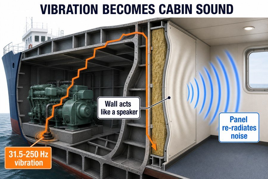
Structure-borne vibration re-radiates as airborne noise when low-frequency engine energy travels through the steel hull into the panel structure. The panel face vibrates, pushing the air at frequencies between 31.5 Hz and 250 Hz, effectively acting like a loudspeaker membrane that broadcasts mechanical vibration as audible sound.
The Journey of Low-Frequency Engine Energy Through the Steel Hull
To understand this problem, you have to track the noise from the source. Ship engines and propellers create massive amounts of low-frequency engine energy. This energy usually sits in the low-frequency bands between 31.5 Hz and 250 Hz.4 In my experience at Magellan Marine, I see this low-frequency energy cause the most trouble. It does not travel through the air. Instead, it enters the solid steel structure of the ship.
Once the vibration enters the steel hull, it travels very fast. Sound waves travel through steel at about 5,000 meters per second.5 This is much faster than sound traveling through the air, which only moves at 343 meters per second. Because the steel is so stiff, the vibration travels through the entire ship without losing much power. It travels from the engine room, up the steel decks, and straight into the accommodation areas.6
Panel Vibration and the Conversion to Audible Sound Frequencies
When this vibration reaches the cabin, it enters the bottom of the marine interior panel. Most standard marine panels have a 0.6mm galvanized steel face. The low-frequency energy makes this thin steel face vibrate back and forth.
This is exactly how a loudspeaker works. The panel face pushes the air inside the cabin. It pushes the air at the exact same frequencies of 31.5 Hz to 250 Hz. The mechanical vibration converts into airborne sound right inside the room.7 You can actually measure this. If the floor vibrates at 63 Hz, a rigid panel will push the air and create a 63 Hz humming noise next to the crew member's bed. The wall itself generates the airborne noise.
| Frequency Range | Source of the Mechanical Energy | Panel Reaction to Vibration | Resulting Audible Noise in Cabin |
|---|---|---|---|
| 31.5 Hz to 63 Hz | Main diesel engine rotation | Slow, heavy flexing of the panel face | Deep, rumbling hum that causes headaches |
| 63 Hz to 125 Hz | Propeller blade passing frequency | Moderate vibration of the steel skin | Noticeable droning noise near the bed |
| 125 Hz to 250 Hz | Auxiliary generators and pumps | Fast, rapid shaking of panel joints | Annoying buzzing sound in the room |
| 250 Hz and above | HVAC fans and small motors | Micro-vibrations on the panel surface | Higher-pitched whine or rattling noise |
Why Is Combined Engine Noise Hard to Solve With a Single Marine Interior Panel Type?
Engine noise is tricky. It attacks your cabin through the air and through the floor. A single simple panel cannot fight two very different battles at the same time.
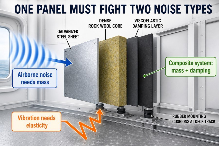
Combined engine noise is hard to solve with a single panel type because it requires contrasting physical properties. Airborne noise demands high mass and dense rockwool to block sound waves, while structure-borne vibration requires elasticity and damping layers to absorb mechanical energy, forcing the use of composite panel systems.
High Mass and Dense Rockwool Requirements for Airborne Noise
When procurement officers try to find low prices in Asia, they often look for simple, cheap panels. But a basic panel cannot stop combined engine noise. To stop airborne noise, the laws of physics say you need mass8. The heavier the wall, the harder it is for sound waves in the air to push through it.
For high airborne noise reduction, we use dense rockwool. A standard marine panel might use rockwool with a density of 100 kg/m3. But to block loud voices and airborne machinery noise, you need rockwool with a density of 120 kg/m3 to 150 kg/m39. This high mass blocks the middle and high frequencies very well. If airborne noise is the only problem, a heavy, solid panel is the perfect solution.
Elasticity and Damping Layer Requirements for Structure-Borne Vibration
However, high mass does nothing to stop structure-borne vibration. In fact, a very rigid, heavy panel can actually transmit vibration better10. To stop mechanical vibration, you need the exact opposite of mass and rigidity. You need elasticity and damping layers.
You need a soft material that can act like a shock absorber. This is why factories build composite panel systems. A good composite panel will have a 2mm or 3mm viscoelastic damping layer glued between the rockwool and the outer steel skin. When the vibration tries to move through the panel, the elastic damping layer absorbs the mechanical energy and turns it into a tiny amount of heat11. Because you need both hard mass and soft elasticity at the same time, you cannot use one simple material. You must combine them into one smart product.
| Noise Type to Control | Required Physical Property | Best Material for the Job | Why This Material Works |
|---|---|---|---|
| Airborne Noise | High Mass and Density | 150 kg/m3 Mineral Rockwool | The heavy weight blocks sound waves from pushing through |
| Airborne Noise | Solid Barrier Surface | 0.6mm Galvanized Steel Sheet | Reflects high-frequency sound waves back into the hallway |
| Structure-Borne Vibration | Elasticity and Flexibility | 3mm Viscoelastic Polymer Layer | Acts as a shock absorber to stop the steel skin from shaking |
| Structure-Borne Vibration | Decoupling / Separation | Rubber Mounting Cushions | Breaks the hard physical connection between the deck and panel |
Why Do Single Acoustic Ratings Fail Against Combined Noise in Marine Accommodation Panels?
You buy a panel with an Rw rating of 44 dB. The rating looks great on paper. But your cabin still fails the final regulatory noise test.
Single acoustic ratings fail against combined noise because metrics like Rw only measure airborne sound transmission loss in a laboratory. They completely ignore low-frequency structure-borne vibration and flanking transmission, meaning real-world shipboard noise levels will always be higher than the lab-tested airborne rating suggests.
The Limitations of Laboratory Rw Ratings in Measuring Airborne Sound
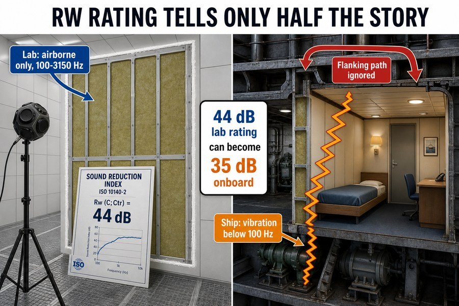
Many buyers only look at one number on a test report: the Rw value. Rw stands for Weighted Sound Reduction Index, defined by the ISO 717-1 standard.12 When a factory tests a panel, they send it to a laboratory. The laboratory places the panel between two concrete rooms. They play a loud noise in one room and measure what comes through to the other room.
This test only measures airborne sound. It measures how well the panel stops sound traveling through the air. The test usually only covers frequencies from 100 Hz up to 3150 Hz.13 It tells you exactly how well the panel will block normal speech or the sound of a television. But a ship is not a concrete laboratory. The single Rw number gives a false sense of security because it only tells half of the story.
The Failure to Account for Low-Frequency Vibration and Flanking Transmission
The laboratory test completely ignores low-frequency structure-borne vibration. Ship engines generate huge amounts of energy below 100 Hz, often at 31.5 Hz or 63 Hz.14 The Rw test does not put a shaking engine under the panel. Therefore, the rating tells you nothing about how the panel handles vibration.
Furthermore, the laboratory test completely seals the panel into the heavy concrete wall. It ignores flanking transmission. On a real ship, you bolt the panel to a thin steel deck. The sound travels through the deck and bypasses the panel.15 Because the Rw rating ignores both the floor vibrations and the flanking paths, a panel rated at 44 dB Rw in the lab might only provide 35 dB of actual noise reduction on the ship. You must plan for this difference when buying materials.
| Test Environment | Type of Noise Measured | Frequencies Tested | Connection to the Floor | Expected Performance |
|---|---|---|---|---|
| ISO Laboratory Test | Pure Airborne Sound Only | 100 Hz to 3150 Hz | Heavy concrete frame, perfectly sealed | High (e.g., 44 dB Rw) |
| Real Ship Cabin | Combined Airborne and Vibration | 31.5 Hz to 3150 Hz | Thin steel deck, rigid U-profiles | Low (e.g., 35 dB Actual) |
| ISO Laboratory Test | Flanking paths ignored | Mid-to-High range | Edges packed with heavy acoustic putty | Perfect isolation |
| Real Ship Cabin | Flanking through ceilings/decks | Low-frequency heavy | Standard marine installation gaps | Sound leaks expected |
How Do Untreated Structure-Borne Paths Mask the Acoustic Benefits of Premium Marine Bulkheads?
You install the best, most expensive bulkheads on the market. But the cabin is just as loud as before. The hidden rigid paths ruin your entire acoustic investment.
Untreated structure-borne paths mask the acoustic benefits of premium marine bulkheads by creating an acoustic short circuit. When rigid metal U-profiles and un-isolated deck tracks directly connect the vibrating steel deck to the premium panel, engine noise bypasses the insulation entirely, rendering the expensive acoustic core completely ineffective.
Creating Acoustic Short Circuits Through Rigid Metal U-Profiles
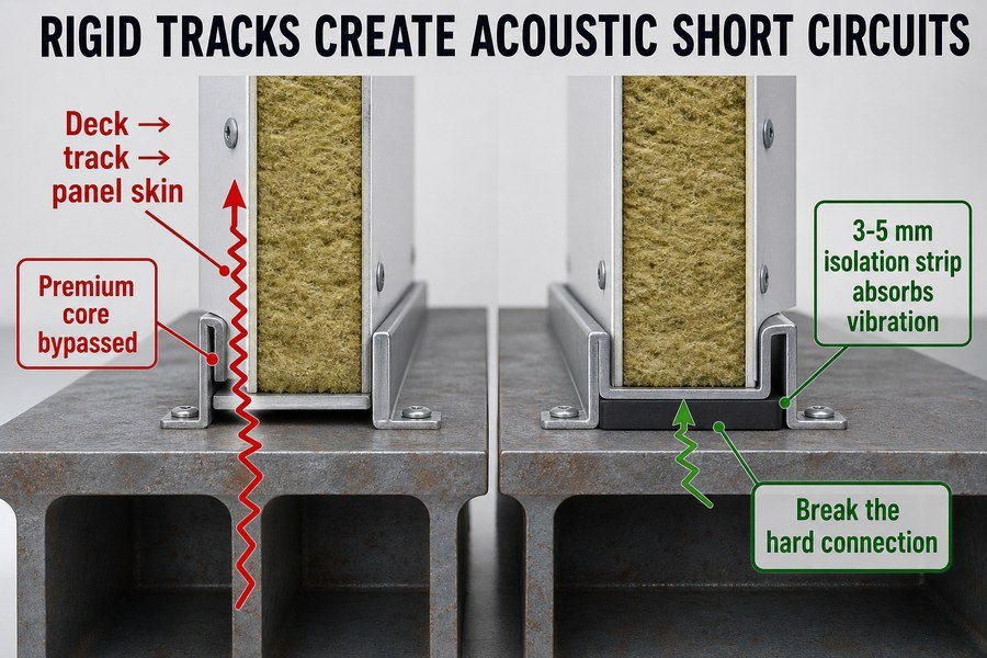
In my outfitting experience, the biggest mistake happens right at the deck level. You can buy a premium, expensive bulkhead with damping layers and dense rockwool. But if you install it wrong, you throw your money away. An acoustic short circuit happens when vibration finds a fast, hard path that goes around your soft insulation.16
Usually, installers screw a rigid metal U-profile directly to the bare steel deck. Then, they slot the premium panel inside this hard steel track. Because steel touches steel, the structure-borne vibration travels straight from the deck, into the metal U-profile, and directly into the metal skin of the bulkhead panel17. The vibration completely bypasses the rockwool inside. The panel skin vibrates and makes noise. This acoustic short circuit masks all the benefits of your premium panel. The panel behaves exactly like a cheap piece of metal.
The Impact of Un-Isolated Deck Tracks on Premium Insulation Cores
To stop this, you must fix the un-isolated deck tracks. You must break the hard physical connection between the ship and the wall. We do this by placing a soft isolation strip under the metal U-profile18 before we screw it down.
Typically, you should use a 3mm to 5mm thick rubber strip, or a high-density mineral wool strip. A rubber with a Shore A hardness of about 60 works well.19 When the deck vibrates, this isolation strip squishes and absorbs the energy. The vibration never reaches the U-profile, so it never reaches the panel skin. By simply spending a few extra dollars on an isolation strip, you protect the expensive acoustic core. This is how you ensure your premium panels actually deliver the quiet cabin you paid for.
| Installation Method | Connection to Steel Deck | Path of the Vibration | Acoustic Performance Result |
|---|---|---|---|
| Un-Isolated Deck Track | Rigid metal screwed directly to deck | Deck ➔ U-Profile ➔ Panel Skin | Total failure; loud humming in cabin |
| 3mm Rubber Strip Isolation | Rubber pad between deck and track | Deck ➔ Rubber (Absorbed) | Excellent; premium panel works well |
| High-Density Wool Strip | Wool tape under the U-profile | Deck ➔ Wool (Absorbed) | Very Good; stops high-frequency buzz |
| Floating Floor System | Panel rests on floating acoustic floor | Deck ➔ Floor Springs ➔ Panel | Perfect; maximum possible noise reduction |
Conclusion
Solving marine cabin noise requires blocking both airborne sound and structure-borne vibration together. By combining dense panels with proper elastic isolation, you can finally deliver quiet, fully compliant ship cabins.
-
"Soundproofing", https://en.wikipedia.org/wiki/Soundproofing. Architectural acoustics references describe flanking transmission as sound bypassing a partition through adjacent constructions or cavities, including ceiling plenums or spaces above partitions. Evidence role: definition; source type: education. Supports: Open spaces above ceiling panels can act as flanking paths that bypass acoustic bulkheads.. Scope note: This supports the acoustic mechanism generally; the exact severity in a ship cabin depends on the ceiling, bulkhead, and installation details. ↩
-
"Analysis of the Underwater Radiated Noise Generated by Hull ...", https://pmc.ncbi.nlm.nih.gov/articles/PMC9861438/. Marine acoustics studies identify diesel engines and propulsion machinery as major sources of structure-borne vibration that can propagate through a ship’s hull and radiate as noise in accommodation areas. Evidence role: mechanism; source type: paper. Supports: Main-engine vibration can travel through ship structure and contribute to cabin noise.. Scope note: The transmission path and level vary with engine mounting, hull structure, isolation design, and operating condition. ↩
-
"[PDF] Effect of opening size on the effectiveness of a noise enclosure ...", https://researchrepository.wvu.edu/cgi/viewcontent.cgi?article=2600&context=etd. Building-acoustics leakage research shows that small unsealed openings can substantially reduce the composite sound transmission loss of an otherwise high-performing partition. Evidence role: statistic; source type: paper. Supports: Very small unsealed gaps can cause large reductions in acoustic panel sound reduction, potentially around 10 dB under some conditions.. Scope note: A specific 10 dB reduction from a 2 mm gap depends on panel area, gap length, frequency range, and the original partition rating, so the cited source should match the assembly conditions as closely as possible. ↩
-
"Relationship between container ship underwater noise levels and ... - PMC", https://pmc.ncbi.nlm.nih.gov/articles/PMC3641522/. A peer-reviewed marine noise study or classification-society guidance can support that ship machinery and propeller-related noise commonly has substantial low-frequency components in octave or one-third-octave bands overlapping 31.5–250 Hz. Evidence role: general_support; source type: paper. Supports: Ship engines and propellers commonly produce problematic low-frequency energy in the 31.5 Hz to 250 Hz range.. Scope note: The source may establish typical frequency ranges for ship noise but not prove that every engine or propeller installation concentrates energy in exactly this band. ↩
-
"Speed of sound - Wikipedia", https://en.wikipedia.org/wiki/Speed_of_sound. A physics or materials reference giving longitudinal sound velocity in steel at roughly 5,000–6,000 m/s supports the stated order of magnitude for wave propagation in steel. Evidence role: statistic; source type: education. Supports: Sound waves travel through steel at about 5,000 meters per second.. Scope note: The exact velocity depends on steel grade, temperature, and wave type, so the figure is an approximate reference value rather than a vessel-specific measurement. ↩
-
"Why Do Marine Accommodation Panels Perform Differently in Labs ...", https://magellanmarinetech.com/why-marine-accommodation-panels-perform-differently-in-labs-versus-onboard/. A naval acoustics reference on structure-borne sound can document that machinery vibration may propagate through hull girders, decks, and bulkheads and become a noise source in accommodation spaces. Evidence role: mechanism; source type: research. Supports: Machinery vibration can propagate through a ship’s steel structure from the engine room to accommodation areas.. Scope note: Such a source supports the transmission mechanism generally; the actual path and attenuation depend on the vessel structure, isolation mounts, and layout. ↩
-
"on the radiation of sound from baffled finite panels", https://ntrs.nasa.gov/api/citations/19770003383/downloads/19770003383.pdf. An architectural or structural acoustics source explaining sound radiation from vibrating plates supports that a wall or panel excited by structural vibration can re-radiate airborne sound into a room. Evidence role: mechanism; source type: paper. Supports: A vibrating marine interior panel can convert structure-borne vibration into airborne sound in the cabin.. Scope note: The source supports the physical mechanism, but the radiated sound level and frequency response depend on panel stiffness, mounting conditions, damping, and room acoustics. ↩
-
"A Comparative Study of Sound Transmission Loss ...", https://www.academia.edu/99904089/A_Comparative_Study_of_Sound_Transmission_Loss_Provided_by_Glass_Acrylic_and_Polycarbonate. A standard acoustics reference on the mass law for sound transmission supports that, for limp or homogeneous barriers, increasing surface mass generally improves airborne sound insulation over much of the frequency range. Evidence role: mechanism; source type: education. Supports: Airborne noise control through a barrier generally requires sufficient mass because heavier barriers are harder for airborne sound to transmit through.. Scope note: The mass law is an idealized model and does not by itself predict performance at resonances, coincidence frequencies, flanking paths, or for complex sandwich panels. ↩
-
"Acoustic Performance of Sound Absorbing Materials ... - PMC", https://pmc.ncbi.nlm.nih.gov/articles/PMC9105389/. Technical and experimental literature on mineral wool absorbers and sandwich panels documents that mineral wool density affects acoustic absorption and panel transmission behavior, providing context for specifying high-density cores in noise-control assemblies. Evidence role: general_support; source type: paper. Supports: Dense rockwool in the range of 120 kg/m3 to 150 kg/m3 is relevant for panels intended to improve airborne noise reduction.. Scope note: Such sources may support the relevance of density ranges for acoustic design but may not directly establish that 120–150 kg/m3 is universally required for all loud-voice or machinery-noise applications. ↩
-
"Review of Modelling and Prediction Methods for Flanking ...", https://upcommons.upc.edu/bitstreams/61ecb1e5-2d31-4e5a-9331-36438f565f22/download. Vibration-isolation literature explains that rigid mechanical connections and stiff structural elements can transmit structure-borne vibration, while isolation performance depends on stiffness, damping, and resonance rather than mass alone. Evidence role: mechanism; source type: education. Supports: A rigid, heavy panel is not necessarily effective against structure-borne vibration and can transmit vibration through stiff mechanical paths.. Scope note: The support is a general mechanical-vibration principle; the exact transmission of a particular marine panel would require measured dynamic stiffness and installation details. ↩
-
"Experimental and Theoretical Investigation of Viscoelastic ...", https://swb.skku.edu/_res/sdr/etc/155.pdf. References on viscoelastic damping describe how cyclic deformation in viscoelastic materials dissipates mechanical vibration energy as heat through internal friction and hysteresis. Evidence role: mechanism; source type: research. Supports: A viscoelastic damping layer can absorb vibration energy and dissipate it as heat.. Scope note: This supports the damping mechanism generally, not the performance of any specific 2 mm or 3 mm damping layer in a finished panel. ↩
-
"Analysis between weighted sound reduction index according to ISO ...", https://www.academia.edu/21437199/Analysis_between_weighted_sound_reduction_index_according_to_ISO_717_1_and_indices_according_to_ISO_16717_1. ISO 717-1 defines single-number ratings for airborne sound insulation, including the weighted sound reduction index Rw, using reference-curve fitting to frequency-band sound reduction data. Evidence role: definition; source type: institution. Supports: Rw is the Weighted Sound Reduction Index defined in ISO 717-1.. ↩
-
"Subjective Evaluation of Airborne Sound Insulation below 100 Hz", https://www.academia.edu/29462475/Subjective_Evaluation_of_Airborne_Sound_Insulation_below_100_Hz. Standard summaries of ISO 717-1 describe Rw as being derived from one-third-octave airborne sound insulation values over the 100 Hz to 3150 Hz range, with optional spectrum adaptation terms for additional frequency ranges. Evidence role: definition; source type: institution. Supports: Rw laboratory evaluation commonly covers the 100 Hz to 3150 Hz frequency range.. Scope note: This supports the conventional Rw evaluation range; individual laboratories may also report extended low- or high-frequency measurements separately. ↩
-
"Why Does Marine Accommodation Panel Acoustic Performance ...", https://magellanmarinetech.com/why-marine-accommodation-panel-acoustic-performance-vary-by-frequency/. Marine noise and vibration studies commonly identify propulsion machinery and diesel engines as important sources of low-frequency airborne and structure-borne noise, with octave-band analysis often including 31.5 Hz and 63 Hz bands. Evidence role: general_support; source type: paper. Supports: Ship engine noise and vibration can have substantial low-frequency components below 100 Hz, including the 31.5 Hz and 63 Hz octave bands.. Scope note: The exact dominant frequencies vary with engine speed, mounting, hull structure, and operating condition, so the source would support the frequency range generally rather than prove every ship engine peaks at 31.5 Hz or 63 Hz. ↩
-
"How Do Structural Connections Impact Marine Ceiling Panel ...", https://magellanmarinetech.com/how-structural-connections-impact-marine-ceiling-panel-acoustics/. Acoustics references on flanking transmission explain that sound can be transmitted through adjoining structural elements rather than only through the separating partition, reducing the apparent field insulation compared with laboratory measurements. Evidence role: mechanism; source type: research. Supports: Flanking transmission can allow sound to bypass an acoustically rated panel through connected structures such as floors or decks.. Scope note: Most general references describe the mechanism for buildings or partitions; a marine-specific source would be needed to document the exact deck-borne path in a particular ship installation. ↩
-
"Review of Modelling and Prediction Methods for Flanking ...", https://upcommons.upc.edu/bitstreams/61ecb1e5-2d31-4e5a-9331-36438f565f22/download. Building- and ship-acoustics literature describes flanking or bypass transmission as sound or vibration travelling through structural connections rather than through the nominal separating element, which supports the article’s use of “acoustic short circuit” for a rigid vibration path around insulation. Evidence role: definition; source type: education. Supports: An acoustic short circuit is a rigid bypass path that lets vibration avoid the intended insulating layer.. Scope note: The terminology may appear more often as “flanking transmission” or “structure-borne transmission” than as the exact phrase “acoustic short circuit.” ↩
-
"How Do Structural Connections Impact Marine Ceiling Panel ...", https://magellanmarinetech.com/how-structural-connections-impact-marine-ceiling-panel-acoustics/. Research on structure-borne sound explains that mechanical vibration can propagate through connected solid elements, including metal structures, and radiate as airborne noise from attached panels; this supports the stated vibration path through a rigid deck-track-panel connection. Evidence role: mechanism; source type: research. Supports: Rigid steel-to-steel connections can transmit structure-borne vibration from a deck through a metal track into a bulkhead panel skin.. Scope note: A general source can support the propagation mechanism, but a ship-specific test would be needed to prove the exact magnitude for a given U-profile installation. ↩
-
"Why Do Marine Accommodation Panels Perform Differently in Labs ...", https://magellanmarinetech.com/why-marine-accommodation-panels-perform-differently-in-labs-versus-onboard/. Guidance on vibration isolation states that resilient interlayers or mounts reduce transmitted vibration by interrupting rigid mechanical coupling and adding compliance between connected structures, which supports the use of an isolation strip beneath a deck track. Evidence role: mechanism; source type: institution. Supports: A soft isolation strip beneath a metal U-profile can reduce vibration transmission by breaking the rigid mechanical connection between deck and wall track.. Scope note: This supports the isolation principle generally; effectiveness depends on strip stiffness, loading, frequency range, and installation details. ↩
-
"Development of elastomeric isolators to reduce roof bolting ...", https://pmc.ncbi.nlm.nih.gov/articles/PMC4642732/. Engineering references on elastomer vibration isolators commonly relate Shore A hardness to rubber stiffness and load-bearing behavior, providing contextual support for specifying a medium-hard rubber such as Shore A 60 in resilient isolation applications. Evidence role: general_support; source type: paper. Supports: A Shore A hardness around 60 is a plausible specification for a rubber isolation strip used to decouple a metal deck track.. Scope note: A generic elastomer reference does not by itself prove that Shore A 60 is optimal for every deck-track load or vibration spectrum; project-specific calculations or testing may be required. ↩