
Are you struggling with cabin noise complaints? Using the exact same acoustic panels for walls and roofs often fails ship sea trials. Let us explore how their structural needs differ.
Marine bulkheads block noise horizontally using rigid, load-bearing sandwich panels with dense rock wool cores (120-150 kg/m³). In contrast, marine ceilings block noise vertically using lightweight panels (80-100 kg/m³) hung with shock-absorbing mounts to utilize the air cavity for enhanced sound transmission loss.
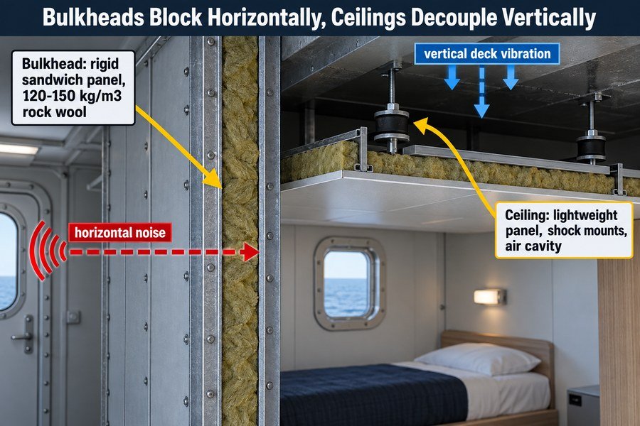
As a marine outfitting specialist, I often see shipyards waste money by mismatching panel types. Understanding these differences will save your next interior project.
How Does a Marine Ceiling's Acoustic Structure Differ from a Marine Bulkhead?
Do you buy the exact same panels for both surfaces? This wastes your budget and hurts performance. Here is how their physical makeups differ fundamentally.
A bulkhead’s acoustic structure relies on thick, double-skin steel panels packed with high-density mineral wool (up to 150 kg/m³) for structural mass. A ceiling’s acoustic structure relies on thinner, single-skin steel panels, lower-density insulation, and a suspended air gap to achieve similar Rw ratings.
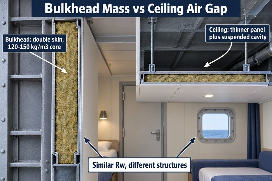
When I first started in a marine outfitting factory, I thought all soundproof panels were the same. I quickly learned that bulkheads and ceilings use very different acoustic strategies. We must understand these two different structures to buy the right materials.
Mass Requirements for Marine Bulkhead Acoustics
A bulkhead relies heavily on mass to block sound. Because it stands vertically and separates two rooms, it does not have a large empty space behind it. We build bulkhead panels as a "sandwich" structure. They have a steel skin on both sides. The steel is usually 0.6mm or 0.7mm thick. Inside, we pack them with high-density rock wool. This density is usually between 120 kg/m³ and 150 kg/m³. According to SOLAS regulations for B-15 fire ratings, this high density provides both fire safety and the heavy mass needed to stop sound waves. More mass means less sound passes through.
Air Gap Utilization in Marine Ceiling Acoustics
A ceiling panel works differently. It hangs from the steel deck above. This creates an empty space, or air gap, above the ceiling. This air gap is a powerful acoustic tool. Because we have this air gap, the ceiling panel itself does not need to be as heavy. We usually use a single steel skin for ceilings. The steel is often thinner, around 0.5mm. The rock wool inside only needs a density of 80 kg/m³ to 100 kg/m³. The combination of the lighter panel and the air gap blocks sound just as well as the heavy bulkhead. Air cavities in double-leaf and suspended ceiling assemblies can increase sound transmission loss through mass-air-mass effects.1 Buying lighter ceiling panels also cuts your shipping costs.
| Feature | Marine Bulkhead Panel | Marine Ceiling Panel |
|---|---|---|
| Steel Skin Design | Double-skin sandwich | Single-skin or thin double-skin |
| Steel Thickness | 0.6mm to 0.7mm | 0.5mm to 0.6mm |
| Rock Wool Density | 120 kg/m³ to 150 kg/m³ | 80 kg/m³ to 100 kg/m³ |
| Primary Sound Blocker | High mass and rigid core | Suspended air cavity and panel mass |
| Installation Weight | Heavy (approx. 18-20 kg/m²) | Light (approx. 12-15 kg/m²) |
Why Does Panel Orientation Change the Build-Up Needed for Equal Sound Insulation in Marine Cabins?
Wondering why a 45dB wall panel fails to deliver 45dB on a roof? Gravity and vibration act differently on horizontal and vertical surfaces. Let me explain.
Panel orientation changes the build-up because vertical bulkheads face direct flanking noise and structural compression, requiring rigid connections. Horizontal ceilings face gravity and structural borne deck vibrations, demanding flexible hangers, shock absorbers, and lightweight cores to prevent sound flanking through the mounting hardware.
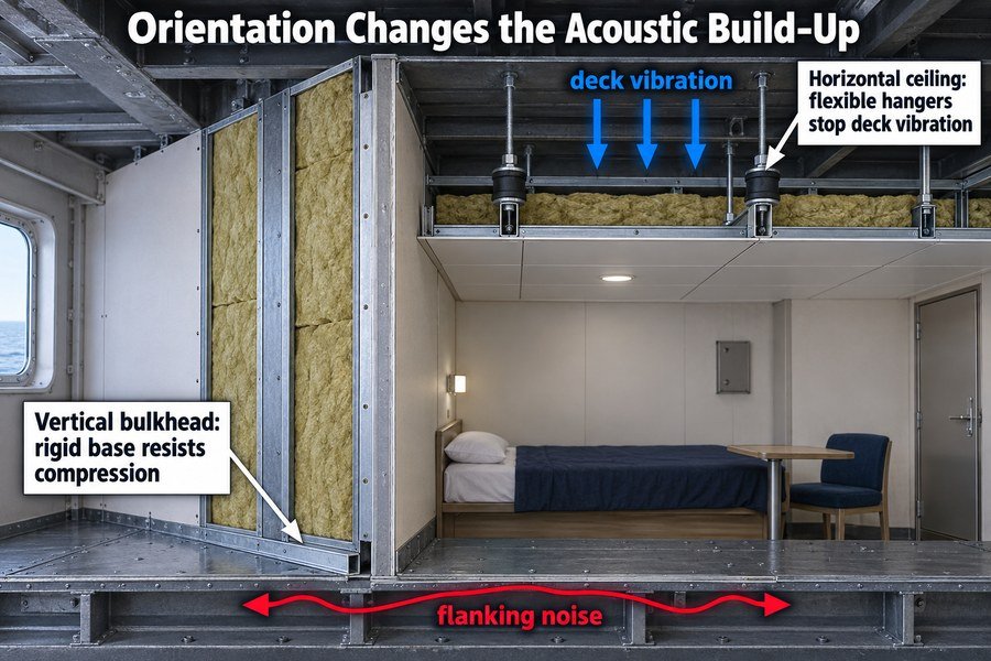
When you place a panel vertically, it fights different forces than when you place it horizontally. This change in orientation means you must change the entire installation build-up to get the same sound insulation.
Managing Compression in Vertical Marine Bulkheads
Vertical bulkheads stand on the deck. They must support their own weight. They also face structural compression from the ship moving. Because of this, we install them with rigid connections. We use U-profile steel tracks bolted directly to the deck. We cannot use soft, bouncy rubber under the wall panels. If we use soft rubber, the wall will shake and crack the joints when the ship rolls. But rigid connections allow flanking noise. Flanking noise is sound that travels through the steel deck and into the wall panel. Flanking transmission describes sound transfer through indirect structural paths such as connected floors, decks, or walls.2 To stop this direct flanking noise, the panel itself must be very heavy and dense to absorb the energy.
Managing Vibration in Horizontal Marine Ceilings
Horizontal ceilings hang above our heads. Gravity pulls them down. At the same time, the steel deck above vibrates heavily from the ship's engine. If we connect the ceiling rigidly to the deck, the engine noise will travel straight down the hangers into the cabin. This is structural borne deck vibration. To fix this, we must use flexible hangers. We install rubber shock absorbers on every hanging rod. These rubber pieces are usually 2mm to 5mm thick. We also use lightweight rock wool cores. A lighter panel puts less stress on the shock absorbers. The flexible hangers and rubber absorbers break the sound path, preventing sound flanking through the mounting hardware. Resilient mounts reduce transmitted vibration by decoupling the source structure from the receiving structure.3
| Orientation Force | Impact on Acoustic Build-up | Required Hardware |
|---|---|---|
| Vertical (Compression) | Requires rigid floor connections to prevent shaking | Steel U-profiles, heavy base plates |
| Vertical (Flanking Noise) | Panel must absorb energy internally | Heavy rock wool core (150 kg/m³) |
| Horizontal (Gravity) | Requires suspension system | Threaded rods, steel C-channels |
| Horizontal (Deck Vibration) | Requires decoupling from the steel deck above | Flexible rubber shock absorbers (2-5mm) |
How Does a Suspended Cavity Affect a Marine Ceiling's Sound Transmission Loss?
Do you cram insulation against the deck overhead? You might be destroying your acoustic rating. That empty space is actually your best sound blocker.
A suspended cavity increases a marine ceiling's sound transmission loss by acting as a decoupling spring. This air gap, typically 100mm to 300mm, traps low-frequency vibrations from the steel deck above, improving the overall Weighted Sound Reduction Index (Rw) by 5 to 10 decibels.
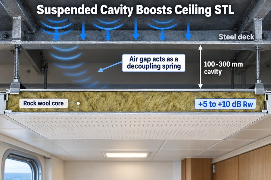
I always tell my clients not to fill the ceiling void completely. Empty air is free, and it is one of the best acoustic materials we have. Let us look at how this cavity works.
The Spring Effect in Marine Ceiling Cavities
In acoustics, we call this the mass-air-mass system. Two rigid leaves separated by an air cavity are commonly modeled as a mass-air-mass acoustic system.4 The top steel deck is the first mass. The ceiling panel is the second mass. The air gap between them acts as a decoupling spring. When engine noise hits the top deck, it pushes the air in the cavity. Because the air acts like a soft spring, it absorbs the energy. It does not push hard against the ceiling panel below. This cavity is excellent at trapping low-frequency vibrations, like engine hums. The gap is typically 100mm to 300mm deep. According to ISO 10140-2 acoustic testing standards, adding a 200mm air cavity can improve the overall Weighted Sound Reduction Index (Rw) by 5 to 10 decibels. Comparable double-panel assemblies show measured sound-insulation gains from increased cavity depth, though exact gains depend on construction details.5
Avoiding Sound Bridges in Ceiling Installations
To make this 5 to 10 decibel improvement work, the cavity must stay clear. Sometimes, workers fill the whole 300mm gap with cheap fiberglass to try and stop more noise. This is a huge mistake. Overfilling the gap creates a physical bridge. The noise travels straight through the packed insulation into the ceiling panel. This destroys the decoupling spring effect. You must also be careful with HVAC ducts and pipes running through this cavity. If a vibrating pipe touches the top of the ceiling panel, you lose your sound transmission loss. The gap must remain an empty air space to function properly.
| Cavity Condition | Acoustic Spring Effect | Estimated Rw Improvement |
|---|---|---|
| No Cavity (Direct Mount) | None | 0 dB |
| 100mm Empty Air Gap | Good low-frequency trapping | +3 to +5 dB |
| 200mm-300mm Empty Air Gap | Excellent low-frequency trapping | +5 to +10 dB |
| Cavity Packed with Insulation | Destroyed (Creates a sound bridge) | -2 to -5 dB loss from peak |
How Do Load-Bearing Requirements Restrict a Marine Bulkhead's Acoustic Design?
Do you want to add more air gaps inside your walls for better acoustics? You cannot always do that. Ship walls must hold weight.
Load-bearing requirements restrict a marine bulkhead's acoustic design by preventing the use of large internal air cavities or ultra-soft isolation materials. Bulkheads must support ceiling loads and resist ship rolling forces, forcing designers to rely on heavy, rigid rock wool cores and stiff steel profiles instead of flexible decoupling.
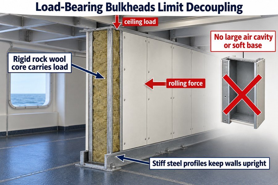
When you design a ship cabin, the walls do a lot of heavy lifting. We cannot make them soft and bouncy just to block sound. Structure always comes first.
Structural Rigidity vs. Acoustic Decoupling in Bulkheads
The best way to block sound is to separate materials with air or ultra-soft isolation materials, like rubber. Air gaps and resilient layers can improve airborne sound insulation by reducing mechanical coupling between panels.6 But bulkheads do not allow this. A B-15 marine bulkhead panel must stand straight and hold weight. It does not have large internal air cavities. If a panel is mostly hollow, it will buckle and collapse. Instead of air, we use heavy, rigid rock wool cores inside the panel. This high-density core (120-150 kg/m³) acts like a solid block. It gives the panel the shear strength it needs to stay flat. We also cannot use ultra-soft rubber bases. If the wall base is too soft, the whole wall will lean over.
Meeting Deck-to-Deck Load Standards
Marine bulkheads must support ceiling loads. The metal frame of the ceiling rests directly on top of the bulkhead panels. The walls carry that weight down to the deck. Furthermore, a ship at sea moves violently. Bulkheads must resist ship rolling forces. The walls must stay perfectly straight when the ship tilts 30 degrees. Maritime stability rules evaluate vessel behavior at large heel angles, giving context for structural loads during rolling.7 Because of these intense physical demands, designers are forced to rely on stiff steel profiles inside the panel joints. We use strong steel splines instead of rubber joints. We solve the acoustic problem with brute mass instead of flexible decoupling.
| Design Element | Acoustic Preference | Load-Bearing Restriction | Solution Used in Bulkheads |
|---|---|---|---|
| Internal Core | Air cavities for decoupling | Will collapse under load | Heavy, rigid rock wool core |
| Base Connection | Ultra-soft rubber isolation | Wall will lean during rolling | Stiff steel U-profiles |
| Panel Joints | Flexible rubber gaskets | Cannot support ceiling loads | Stiff steel connection splines |
| Sound Strategy | Flexible decoupling | Fails structural tests | High mass and density |
How Can Engineers Align Acoustic Designs for Both Bulkhead and Ceiling Rw Targets on One Marine Project?
Are your cabin noise tests still failing despite buying expensive panels? The secret is treating the room as one system. Here is how we align them.
Engineers align acoustic designs by combining high-mass bulkheads (40-45 dB Rw) with cavity-backed ceilings (45-50 dB Rw), sealing all joints with acoustic sealants, isolating the ceiling hangers, and using a floating floor system. This 4-part strategy prevents flanking noise and meets strict DNV or Lloyd's Register cabin limits.
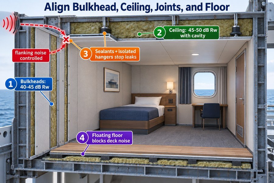
You cannot buy a 45 dB wall, a 45 dB ceiling, throw them together, and expect the room to test at 45 dB. Sound leaks through the weak points. We must align the system.
Balancing Panel Mass Between Bulkheads and Ceilings
First, we select the right panels for the 4-part strategy. We start by combining high-mass bulkheads with cavity-backed ceilings. For a standard crew cabin, we use 50mm thick bulkheads rated for 40-45 dB Rw. Because bulkheads lack an air gap, getting higher than 45 dB is very expensive. Single solid barriers generally require more mass to improve airborne sound insulation, while separated leaves can improve isolation through mass-air-mass behavior.8 We make up for this on the roof. We use a lighter ceiling panel but take advantage of the 200mm air gap. This cavity-backed ceiling easily achieves 45-50 dB Rw. By pairing a 45 dB wall with a 50 dB ceiling, we balance the performance. We put the acoustic power where it is cheapest to achieve.
Implementing the 4-Part Acoustic Alignment Strategy
Selecting panels is only part one and two. Next, we must focus on the connections. Sound acts like water; it finds the smallest hole. We must seal all joints with acoustic sealants. Every corner where a bulkhead meets the ceiling gets a thick line of fire-rated acoustic silicone. Next, we stop the vibration. We isolate the ceiling hangers using the rubber shock absorbers I mentioned earlier. Finally, we install a floating floor system. The bulkheads sit on top of 50mm high-density mineral wool floor boards, covered by 2mm steel plates. This completely separates the room from the steel ship deck. This complete 4-part strategy is the only way to meet strict DNV or Lloyd's Register cabin limits, which usually require noise levels below 55 dB(A) inside the cabin. Marine noise rules and comfort-class notations specify maximum A-weighted sound pressure levels for accommodation spaces.9
| Strategy Step | Component Used | Acoustic Purpose | Target Rw / Performance |
|---|---|---|---|
| 1. High-Mass Bulkheads | 50mm Sandwich Panels (150 kg/m³) | Block horizontal room-to-room noise | 40-45 dB Rw |
| 2. Cavity-Backed Ceilings | Lighter Panels + 200mm Air Gap | Block vertical deck engine noise | 45-50 dB Rw |
| 3. Sealants & Isolated Hangers | Acoustic Silicone & Rubber Mounts | Stop sound leaks and deck vibration | Prevents 5-10 dB system loss |
| 4. Floating Floor System | Floor Rock Wool + Steel Plates | Block upward structural noise | Meets DNV < 55 dB(A) cabin limit |
Conclusion
Bulkhead and ceiling acoustic designs differ heavily due to gravity, air cavities, and load-bearing needs. Match the correct panel structure to its location to pass sea trials and control costs.
-
"Airborne sound insulation performance of lightweight double ...", https://pmc.ncbi.nlm.nih.gov/articles/PMC11666719/. Research on double-leaf partitions and suspended ceiling assemblies shows that an air cavity, especially when combined with porous absorption, can increase sound transmission loss through mass-air-mass effects; equivalence to a particular marine bulkhead construction requires test data for the exact panel, cavity depth, mounting, and penetrations. Evidence role: mechanism; source type: paper. Supports: The combination of the lighter panel and the air gap blocks sound just as well as the heavy bulkhead. Scope note: Provides acoustic mechanism support, but not direct proof that the specified lighter ceiling panel matches the specified bulkhead in every installation. ↩
-
"Flanking transmission", https://en.wikipedia.org/wiki/Flanking_transmission. Standard acoustic references define flanking transmission as sound transfer by indirect structural paths, supporting the explanation that vibration can bypass the direct partition path through connected floors, decks, or walls. Evidence role: definition; source type: encyclopedia. Supports: Flanking noise can travel through connected structural elements such as a deck and into a wall panel. Scope note: A general building-acoustics source may define the mechanism without specifically naming steel ship decks. ↩
-
"How to Match a Marine Accommodation Panel System to the ...", https://magellanmarinetech.com/how-match-marine-accommodation-panel-system-to-the-correct-noise-path/. Vibration-isolation references describe resilient mounts as reducing transmitted vibration by decoupling the source structure from the receiving structure, supporting the use of flexible hangers to limit structure-borne flanking through mounting hardware. Evidence role: mechanism; source type: research. Supports: Flexible hangers and rubber absorbers reduce structure-borne sound transmission through ceiling mounting hardware. Scope note: This supports the isolation mechanism but does not verify the performance of the specific rubber thickness or hanger layout stated in the article. ↩
-
"[PDF] The finite layer method for modelling the sound transmission ...", https://upcommons.upc.edu/bitstreams/6ce7ff3e-10c0-4bbc-baa9-c0aea47a9c5a/download. A building-acoustics reference or textbook source should document that two rigid leaves separated by an air cavity are modeled as a mass-air-mass system, with the enclosed air acting as a compliant coupling that influences sound transmission, especially around the system resonance. Evidence role: definition; source type: education. Supports: A steel deck, ceiling panel, and intervening air gap can be described as a mass-air-mass acoustic system. Scope note: This supports the general acoustic model; performance in a specific marine ceiling depends on panel mass, cavity depth, mounting details, damping, and flanking paths. ↩
-
"Airborne sound insulation performance of lightweight double ...", https://pmc.ncbi.nlm.nih.gov/articles/PMC11666719/. ISO 10140-2 should be cited only to establish the laboratory method for measuring airborne sound insulation, while a separate peer-reviewed or institutional acoustics source is needed to substantiate any reported 5-10 dB Rw change from increasing cavity depth. Evidence role: statistic; source type: institution. Supports: A 200 mm air cavity can improve the measured Weighted Sound Reduction Index by roughly 5 to 10 dB in comparable ceiling or double-panel assemblies. Scope note: ISO 10140-2 specifies a test procedure rather than a universal performance gain; the stated dB improvement must be supported by test data for comparable constructions. ↩
-
"[PDF] Review of Modelling and Prediction Methods for Flanking ...", https://upcommons.upc.edu/bitstreams/61ecb1e5-2d31-4e5a-9331-36438f565f22/download. Building-acoustics literature describes the mass-air-mass principle and resilient layers as mechanisms that can improve airborne sound insulation by reducing mechanical coupling between panels. Evidence role: mechanism; source type: paper. Supports: Separating materials with air gaps or resilient isolation layers can improve sound blocking by acoustic decoupling. Scope note: This supports the acoustic mechanism in general; it does not prove that these approaches are optimal or feasible for every marine bulkhead design. ↩
-
"46 CFR Part 171 -- Special Rules Pertaining to Vessels ...", https://www.ecfr.gov/current/title-46/chapter-I/subchapter-S/part-171. Maritime stability rules commonly evaluate vessel behavior at large heel angles, including around 30 degrees, providing context for why accommodation bulkheads and their connections must tolerate significant inclination and ship-motion loads. Evidence role: historical_context; source type: institution. Supports: Ship bulkheads must remain structurally stable under significant heel or rolling conditions, such as around 30 degrees of inclination. Scope note: Such stability criteria establish the operating-load context for ship structures, but they may not directly require an individual bulkhead panel to remain "perfectly straight" at exactly 30 degrees. ↩
-
"Investigation of transmission loss through double wall ...", https://ir.library.louisville.edu/etd/1760/. Acoustics references on the mass law and double-leaf partitions show that single solid barriers generally require increased mass to improve airborne sound insulation, while separated leaves with an air cavity can improve isolation through mass-air-mass behavior. Evidence role: mechanism; source type: education. Supports: Bulkheads without an air gap become less efficient to improve acoustically compared with cavity-backed assemblies. Scope note: The source would support the acoustic mechanism, but it would not directly prove the stated cost threshold or the exact 45 dB value for these bulkheads. ↩
-
"How Do Owner Requirements Raise Cabin Noise Standards?", https://magellanmarinetech.com/how-owner-requirements-raise-cabin-noise-standards/. Marine noise rules and comfort-class notations from bodies such as the IMO, DNV, and classification societies specify maximum A-weighted sound pressure levels for accommodation spaces, including cabins, as part of onboard habitability requirements. Evidence role: statistic; source type: institution. Supports: Strict marine accommodation standards may require cabin noise levels around or below 55 dB(A). Scope note: Such sources can verify applicable cabin noise limits, but they do not prove that the described four-part assembly is the only method capable of meeting them; limits also vary by vessel type, notation, and comfort class. ↩