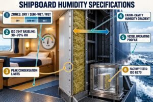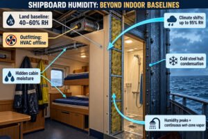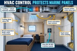
Moisture ruins ship interiors fast. Hidden dampness degrades rockwool cores and peels PVC films, causing costly shipyard rework. Controlling humidity across different spaces protects your panels.
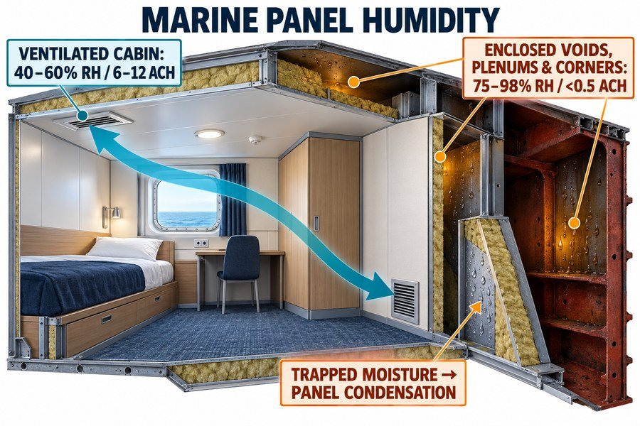
Per ISO 7547, ventilated marine cabins maintain 40% to 60% relative humidity through 6 to 12 air changes per hour. Conversely, enclosed spaces—including hull voids, overhead plenums, and blocked corners—trap 75% to 98% relative humidity with under 0.5 air changes per hour, causing severe panel condensation.
I started my career on the factory floor of a marine outfitting plant. Today, I work at Magellan Marine as a marine outfitting specialist. I help procurement managers source high-quality marine wall panels, ceiling panels, and fire doors from Asia for major shipyards in Europe and the United States. Many buyers focus heavily on fire certificates, factory prices, and delivery lead times. However, they often overlook how shipboard air movement changes moisture levels around panels. When a vessel sails from a humid Asian port to a cold European shipyard, trapped moisture in dead air spaces can destroy panel cores before the ship even enters service. Let us look closely at why enclosed and ventilated spaces create completely different humidity levels and how you can specify the right materials to avoid expensive claims.
Why Do Enclosed Ship Spaces Trap Higher Humidity Around Marine Interior Panels?
You buy certified marine panels, yet rust and mold appear within months. Enclosed ship zones trap wet air endlessly. Identifying these traps stops premature panel failure.
Enclosed ship spaces trap 75% to 95% relative humidity due to four main factors: stagnant air under 0.05 m/s, steel hull thermal bridging below the dew point, utility pipe condensation, and low panel vapor permeability (under 1.0 perm per ASTM E96), which blocks moisture from escaping.
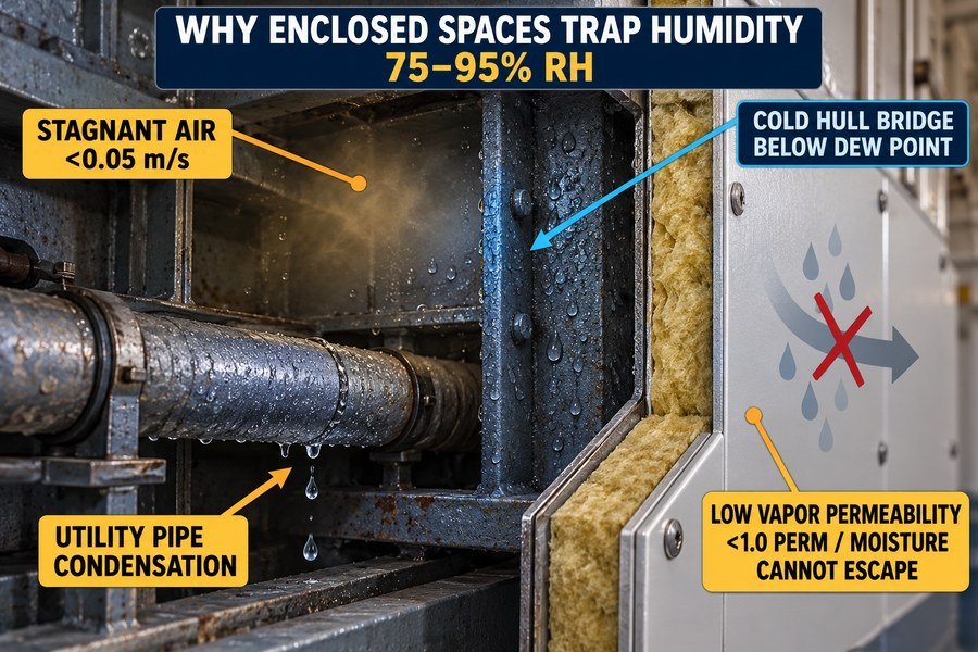
Stagnant Air Velocity and Steel Hull Thermal Bridging in Enclosed Ship Zones
In my daily work at Magellan Marine, I often review warranty photos from interior contractors. Most rust stains start on the hidden back side of marine panels. The first factor behind this damage is stagnant air velocity. According to ASHRAE Standard 26 and ISO 7547 marine HVAC guidelines, ventilated cabins maintain air speeds between 0.15 m/s and 0.25 m/s. In contrast, enclosed spaces behind bulkheads have air speeds below 0.05 m/s. Because the air does not move, water vapor cannot disperse. The second factor is steel hull thermal bridging. A ship hull sits directly in cold seawater, which often ranges from 2°C to 10°C in North Atlantic or North Sea routes1. Steel has a high thermal conductivity of about 50 W/m·K2. Even when workers attach 50 mm A-60 mineral wool pins to the steel ribs, the steel frames act as cold bridges. When internal air at 24°C touches steel surfaces cooled to 12°C, the local air drops below its dew point. This drop drives relative humidity in the enclosed space up to 85% or 95% within hours.
Utility Pipe Condensation and Low Panel Vapor Permeability Barriers
The third factor is utility pipe condensation inside enclosed chases. Shipbuilders route chilled water lines, cold freshwater pipes, and sanitary drains behind wall panels and above ceilings. These pipes usually carry water at 7°C to 12°C. If the closed-cell rubber pipe insulation has even a 5 mm gap at a valve or hanger, the cold pipe sweats continuously. One meter of uninsulated 50 mm chilled water pipe can release 150 grams to 300 grams of liquid water per day into an enclosed cavity. The fourth factor is low panel vapor permeability. Standard B-15 and B-0 marine wall panels use 0.5 mm to 0.7 mm galvanized steel sheets covered with a 0.15 mm decorative PVC film on both faces. Under ASTM E96 testing, this steel and PVC assembly has a water vapor permeance below 0.1 perm3 (well under the 1.0 perm class threshold for vapor retarders). While this barrier stops cabin humidity from entering the core, it also traps any moisture that enters the enclosed void from behind. The trapped water sits against the galvanized zinc coating until white rust and red rust form.
| Humidity Trapping Factor | Enclosed Space Value | Ventilated Cabin Value | Authoritative Standard / Source | Direct Impact on Marine Panels |
|---|---|---|---|---|
| Airflow Velocity | Less than 0.05 m/s | 0.15 to 0.25 m/s | ISO 7547 / ASHRAE Std 26 | Moist air pockets stay trapped against steel skins |
| Thermal Bridging Delta-T | 10°C to 18°C drop at hull ribs | Less than 2°C variation | ISO 7547 Marine Design | Rapid dew point condensation on panel backing |
| Utility Pipe Sweat Rate | 150 to 300 g/m² per day | 0 g/m² (insulated & vented) | IACS Piping Guidelines | Water pools inside bottom C-channel tracks |
| Panel Vapor Permeance | Under 0.1 perm (steel/PVC) | Under 0.1 perm (steel/PVC) | ASTM E96 Vapor Test | Moisture cannot evaporate through the panel wall |
How Does Continuous Air Circulation Reduce Surface Moisture on Marine Interior Panels?
Water droplets on cabin walls ruin decorative PVC films quickly. Static air lets dampness settle on cold steel skins. Continuous airflow dries panels before damage starts.
Continuous air circulation reduces marine panel surface moisture through three mechanisms: disrupting the moist boundary layer at air speeds of 0.15 to 0.25 m/s (ISO 7547), equalizing panel skin temperature within 2°C of ambient air, and exhausting humid cabin air at 6 to 15 air changes per hour.
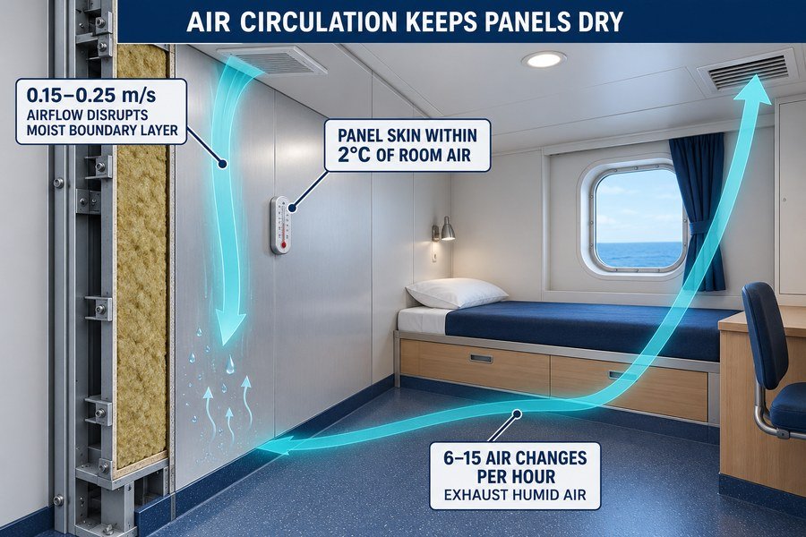
Boundary Layer Disruption and Panel Skin Temperature Equalization
Last year, I helped a procurement client who was outfitting a cruise vessel in a European shipyard. They turned off the temporary HVAC blowers during a rainy weekend to save power. By Monday morning, water droplets covered every corridor wall panel. Continuous air circulation stops this problem through three physical mechanisms. First, airflow disrupts the stagnant boundary layer on the panel surface4. Every wall panel has a microscopic film of still air clinging to its PVC surface. When people breathe or shower in a cabin, moisture collects in this boundary layer. According to ISO 7547, keeping cabin air velocity between 0.15 m/s and 0.25 m/s strips away this saturated film and replaces it with conditioned dry air. This movement boosts surface evaporation rates from under 5 g/m² per hour in still air to 25 or 40 g/m² per hour in moving air. Second, continuous circulation equalizes the panel skin temperature with the room air. In a room kept at 22°C, steady airflow warms the 0.6 mm galvanized steel face so it stays within 1°C to 2°C of the ambient temperature. At 22°C and 50% relative humidity, the dew point is 11.1°C.5 Because the moving air keeps the panel surface around 20°C to 21°C, surface condensation cannot form.
Moisture Exhaust Rates Through Regulated Cabin Air Changes Per Hour
The third mechanism is exhausting humid air through regulated air changes per hour (ACH). Two crew members sleeping in a standard 15 m² cabin release about 80 grams to 120 grams of water vapor per hour6 through breathing and skin perspiration. Inside a modular wet unit, a single hot shower releases 300 grams to 500 grams of steam in 10 minutes. Without constant exhaust, room humidity reaches 90% in fifteen minutes. ISO 7547 and ASHRAE Standard 26 require 6 to 8 air changes per hour for living cabins, 10 to 12 air changes per hour for mess rooms, and 15 air changes per hour for sanitary wet units. When the HVAC system replaces the entire room air volume 6 to 15 times every hour with dehumidified supply air (typically conditioned to a specific humidity of 7 to 9 grams of water per kilogram of dry air), excess vapor exits through the exhaust duct before the PVC film or silicone joint sealants can absorb it.
| Ship Accommodation Zone | Required Air Changes (ACH) | Target Air Velocity (m/s) | Surface Evaporation Rate | Target Relative Humidity | Authoritative Source |
|---|---|---|---|---|---|
| Crew & Passenger Cabins | 6 to 8 ACH | 0.15 to 0.20 m/s | 20 to 30 g/m²/hr | 45% to 55% RH | ISO 7547 |
| Mess Rooms & Lounges | 10 to 12 ACH | 0.20 to 0.25 m/s | 25 to 40 g/m²/hr | 40% to 55% RH | ISO 7547 / ASHRAE 26 |
| Sanitary Wet Units | 15 ACH (Negative Pressure) | 0.20 to 0.30 m/s | 35 to 50 g/m²/hr | 50% to 65% RH | ISO 7547 |
| Unventilated Store Rooms | 0 to 0.5 ACH | Under 0.05 m/s | Under 5 g/m²/hr | 75% to 95% RH | Shipyard Field Data |
What Humidity Conditions Exist in Enclosed Voids Behind Marine Lining Panels?
Your cabin walls look spotless inside, but hidden corrosion eats the steel behind them. Unseen hull voids experience extreme dampness. Knowing these conditions prevents hidden rot.
Enclosed voids behind marine lining panels experience four severe humidity conditions: relative humidity reaching 85% to 98%, steel-to-cabin temperature drops of 8°C to 15°C (ISO 7547), liquid sweat accumulation of 150 to 400 g/m² daily, and rockwool core moisture absorption exceeding 2% by weight (IMO FTPC).
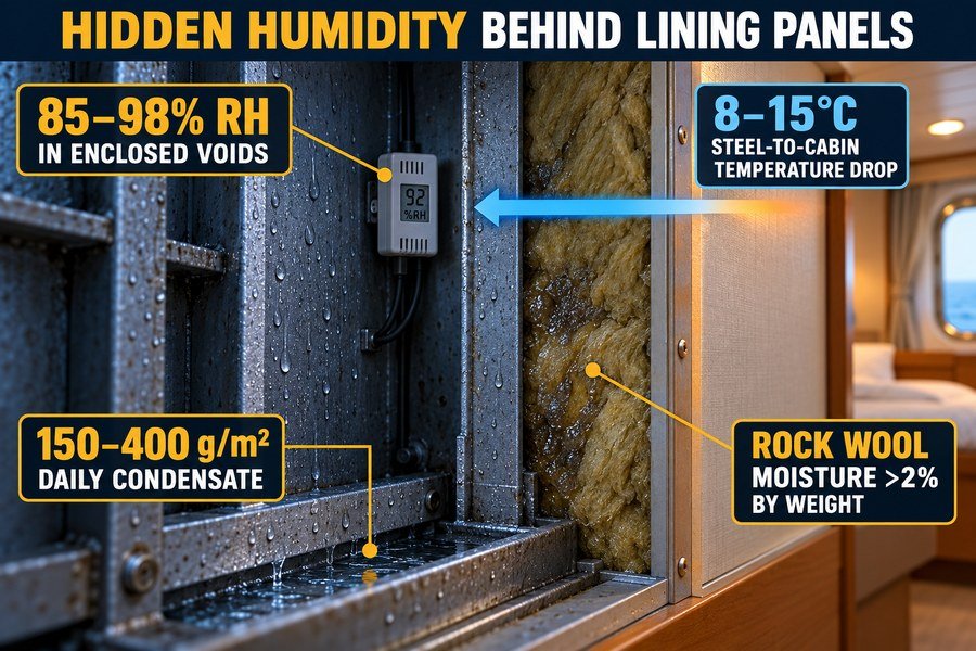
Extreme Relative Humidity and Thermal Gradients in Hull-to-Lining Cavities
A lining panel is the single-sided marine wall panel installed along the exterior steel hull or bulkheads. Installers leave a 50 mm to 150 mm enclosed air void7 between the hull insulation and the back of the B-15 lining panel to run electrical cables and pipes. This cavity faces four harsh humidity conditions. First, relative humidity inside the void regularly stays between 85% and 98%8. Even small gaps around electrical socket boxes allow warm cabin air to leak into the cold cavity. Because the cavity has no exhaust vent, the trapped moisture saturates the air. Second, the cavity experiences steep steel-to-cabin temperature drops of 8°C to 15°C. Under ISO 7547 winter design rules9, outdoor air is calculated at -15°C to -20°C while the interior cabin is heated to +22°C. Even with 75 mm of hull mineral wool, the air inside the unheated lining void often sits at 7°C to 12°C. In summer tropical conditions (+35°C outside at 80% relative humidity and +24°C inside), the thermal gradient reverses, driving hot humid air inward against the air-conditioned back sheet of the lining panel.
Daily Hull Sweat Accumulation and Rockwool Core Moisture Absorption Limits
The third condition is liquid sweat accumulation. When moist cavity air hits cold hull stiffeners or the back of cooled lining panels, water condenses at a rate of 150 to 400 g/m² per day10. This liquid water runs down the steel frames and collects inside the bottom galvanized floor track (U-profile). If the zinc coating on the floor track is only 80 g/m² instead of the marine standard 275 g/m² (Z275), red rust eats through the 1.2 mm steel track in less than 18 months. The fourth condition is rockwool core moisture absorption. Many lining panels have an exposed or perforated mineral wool back face for acoustic insulation or cost reduction. Standard low-grade rockwool absorbs up to 5% or 8% moisture by weight in 95% humidity. Under IMO 2010 FTP Code (FTPC) and EN 1609 standards, marine-grade hydrophobic rockwool (density 120 to 150 kg/m³) must limit water absorption to less than 1.0 kg/m² (typically under 1% to 2% by weight). When a buyer sources cheap panels without silicone water-repellent treatment, the rockwool core absorbs over 2% moisture by weight. The core becomes heavy, sags inside the panel frame, and loses 30% to 40% of its thermal resistance.
| Sailing Climate Zone | Hull Void Relative Humidity | Void Temperature Drop (Delta-T) | Daily Sweat Accumulation | Unprotected Rockwool Moisture Gain | Authoritative Standard |
|---|---|---|---|---|---|
| Tropical Waters (+35°C Ext) | 88% to 98% RH | 8°C to 11°C | 250 to 400 g/m²/day | 3.5% to 6.0% by weight | ISO 7547 / EN 1609 |
| Winter / Arctic (-20°C Ext) | 85% to 95% RH | 12°C to 15°C | 200 to 350 g/m²/day | 2.5% to 5.0% by weight | ISO 7547 |
| Temperate Routes (+15°C Ext) | 75% to 85% RH | 5°C to 8°C | 150 to 220 g/m²/day | 1.5% to 2.5% by weight | Shipyard Survey Data |
| Hydrophobic Spec Limit | Tested at 95% RH | Tested at 15°C Delta-T | Drained via weep holes | Under 1.0% to 2.0% max | IMO FTPC / EN 1609 |
Why Do Overhead Service Plenums Trap Moisture Above Marine Ceiling Panels?
Dripping ceiling panels stain cabin carpets and ruin recessed lights. Overhead service plenums collect heavy moisture above your cabins. Fixing plenum traps protects your ceiling systems.
Overhead service plenums trap 80% to 95% relative humidity above marine ceiling panels due to four causes: uninsulated chilled water pipe sweating, bathroom exhaust duct leakage (2% to 5% volume loss), warm moist air buoyancy through ceiling joints, and zero plenum ventilation required by SOLAS B-Class fire barriers.
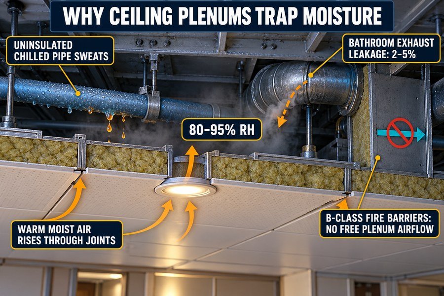
Chilled Water Pipe Sweating and Exhaust Duct Leakage in Ceiling Plenums
The 300 mm to 600 mm space between the marine ceiling panel and the steel deck head above is called the overhead service plenum. In my experience supplying B-0 and B-15 ceiling panels at Magellan Marine, ceiling water damage almost always originates from four plenum issues. First, chilled water pipes and cold air supply ducts sweat heavily in the plenum. Chilled water pipes carry water at 6°C to 12°C across the top of the ceiling panels to feed cabin fan coil units. Shipyard pipefitters often compress or tear the 19 mm nitrile rubber insulation where pipes pass through steel deck beams. Exposed cold pipe sections condense water rapidly11, dripping directly onto the top mineral wool layer of the 300 mm wide M-profile ceiling planks. Second, bathroom exhaust ducts leak wet air into the plenum. Under ISO 7547 and IACS ductwork testing rules, low-pressure spiral or rectangular exhaust ducts can lose 2% to 5% of their airflow volume through unsealed flange gaskets or pop-rivet seams. Because bathroom exhaust ducts carry 80% to 95% relative humidity air12 from multiple wet units, a 3% leak pumps liters of warm water vapor directly into the closed ceiling space every day.
Warm Air Buoyancy and SOLAS Fire Barrier Airflow Restrictions
The third cause is warm moist air buoyancy. Warm cabin air is lighter than cool air, so it naturally rises toward the ceiling. Marine B-15 ceiling planks connect using tongue-and-groove joints with a 0.5 mm to 1.0 mm mechanical tolerance. In addition, electricians cut holes in the ceiling panels for IP44 recessed LED downlights, Wi-Fi antennas, and PA speakers. Warm, humid air from the cabin rises through these tiny gaps into the cooler overhead plenum. Once inside the plenum, the air cools against the upper steel deck and hits 85% to 95% relative humidity. The fourth cause is zero plenum ventilation caused by SOLAS fire regulations. Under SOLAS Chapter II-2, Regulation 9, shipbuilders must install continuous B-0 or B-15 ceilings or steel draft stops every 14 meters to block smoke and flame spread above ceilings. Because of this strict fire rule, engineers cannot blow ventilation air freely through the overhead plenum. The moisture remains locked inside 14-meter fire compartments, soaking the top of the ceiling panels and corroding the galvanized M-bars and threaded suspension rods.
| Plenum Moisture Cause | Typical Moisture / Leakage Rate | Resulting Plenum Humidity | Authoritative Standard | Practical Engineering Fix |
|---|---|---|---|---|
| Chilled Water Pipe Sweating | 200 to 450 g/m of exposed pipe/day | 85% to 95% RH | IACS Piping / ASHRAE | Apply 25 mm closed-cell insulation with glued seams |
| Exhaust Duct Seam Leakage | 2% to 5% of total exhaust volume | 80% to 92% RH | ISO 7547 Duct Class A | Keep wet exhaust fans at deck end for negative duct pressure |
| Cabin Air Buoyancy Infiltration | 0.5 to 1.5 m³/hr per light cutout | 75% to 88% RH | IP44 / Marine Elec Rules | Use sealed back-cans and foil-backed rockwool on ceilings |
| SOLAS Draft Stop Containment | 0 ACH (sealed every 14 meters) | 80% to 95% RH | SOLAS Ch. II-2 Reg. 9 | Specify aluminum foil vapor barrier on top of ceiling wool |
Why Do Corners, Recesses, and Furniture Trap Humidity Against Marine Wall Panels?
Mold always grows behind cabin beds and inside tight corners first. Fixed furniture blocks airflow and traps dampness against walls. Addressing these dead zones prevents delamination.
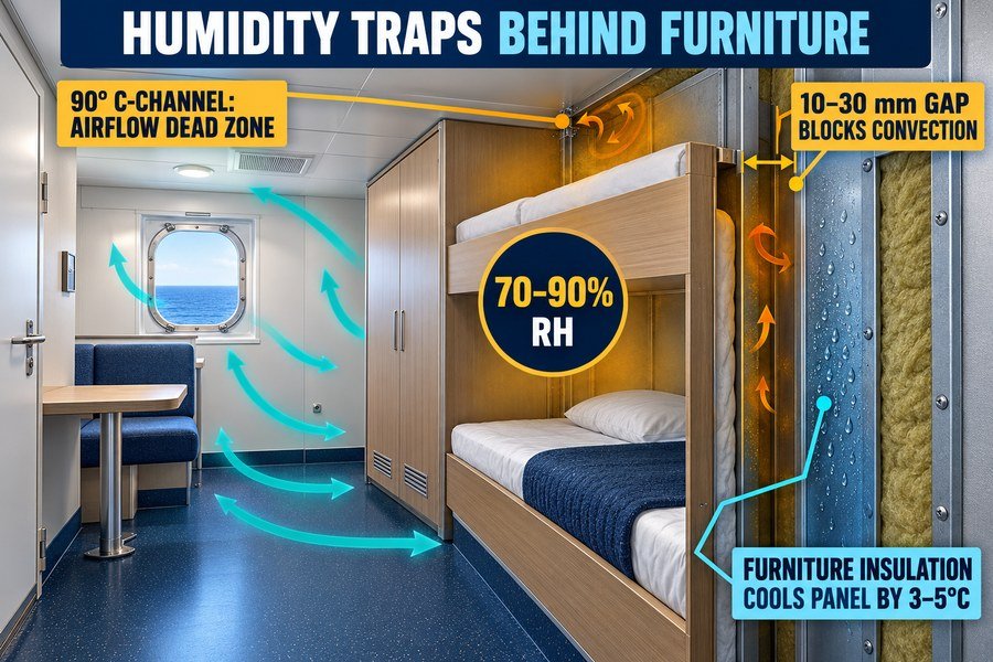
Corners, recesses, and fixed furniture trap 70% to 90% relative humidity against marine wall panels because of three factors: 90-degree C-channel profiles creating airflow eddy dead zones, 10 to 30 mm furniture-to-wall gaps blocking convection, and furniture insulation lowering wall panel surface temperatures by 3°C to 5°C.
Airflow Eddy Dead Zones in 90-Degree Corner Profiles and Structural Recesses
Even in a well-ventilated cabin where the center of the room stays at 50% relative humidity, specific wall panel areas still suffer from moisture damage. When I inspect refurbished vessels, I always check the cabin corners and the areas behind fixed bunks first. Three physical factors turn these spots into humidity traps. First, 90-degree corner profiles and structural recesses create airflow eddy dead zones. Marine wall panels join at room corners using galvanized steel C-channels or two-piece PVC-laminated corner posts. Fluid dynamics principles under ASHRAE Standard 26 show that air flowing parallel to a cabin wall separates when it approaches a sharp 90-degree corner or a 200 mm deep pillar recess13. While the center of the room enjoys an air speed of 0.20 m/s, the air velocity inside the 50 mm corner zone drops below 0.02 m/s14. Because the air stagnates in these corners, moisture from cabin mopping or wet work clothes lingers for hours, raising corner relative humidity to 70% or 80%15.
Blocked Convection and Thermal Shielding Behind Fixed Cabin Furniture
The second factor is blocked convection inside the 10 mm to 30 mm gap between fixed cabin furniture and marine wall panels. Unlike residential furniture, marine beds, wardrobes, and desks bolt directly to the deck and the B-15 wall panels to prevent movement in rough seas. Carpenters leave a narrow 10 mm to 30 mm gap between the back of the plywood wardrobe and the PVC wall panel to accommodate joint profiles. Air cannot circulate inside this narrow slot. Worse, crew members sleeping on a bunk release body moisture16 that migrates directly into the gap behind the mattress. The third factor is furniture thermal shielding. A wooden wardrobe stuffed with clothes or a thick marine mattress acts as a thermal insulator with an R-value of 1.5 to 2.5 m²·K/W17. This furniture blocks the warm 22°C cabin air from heating the wall panel behind it. If the wall panel sits against a cool exterior bulkhead or an air-conditioned corridor, the panel surface temperature behind the furniture drops by 3°C to 5°C compared to the open wall. A 4°C temperature drop raises the local relative humidity at the panel surface by 12% to 18%, pushing it straight to 85% or 90% relative humidity. Over time, this dampness weakens inferior water-based PVC glue and causes the decorative film to bubble. At Magellan Marine, we use two-component polyurethane (PU) glue applied at 60 to 80 g/m², which costs only $0.50 more per square meter than water-based glue but completely prevents moisture peeling in these tight zones.
| Cabin Micro-Climate Zone | Local Air Velocity | Surface Temp Drop | Local Relative Humidity | Common Panel Failure Mode | Recommended Prevention Spec |
|---|---|---|---|---|---|
| Center of Open Wall Panel | 0.15 to 0.25 m/s | 0°C (Baseline) | 45% to 55% RH | None (Dry surface) | Standard B-15 PVC steel panel |
| 90-Degree Corner C-Profile | Under 0.02 m/s | 1°C to 2°C drop | 70% to 80% RH | Mold in silicone corner joint | Use anti-fungal sanitary silicone |
| Behind Fixed Bunk / Mattress | Under 0.01 m/s | 3°C to 4°C drop | 75% to 88% RH | PVC film blistering & peeling | Specify 2-part PU film adhesive |
| Behind Hull-Side Wardrobe | Under 0.01 m/s | 4°C to 5°C drop | 80% to 90% RH | Hidden rust at mounting screws | Add 20 mm vent slots in plinth & top |
How Does HVAC Duct Layout Affect Localized Humidity Around Marine Accommodation Panels?
Poor duct placement ruins expensive marine panels even with a strong chiller. Uneven airflow creates wet patches and peeling PVC skins. Proper duct layout protects cabins.
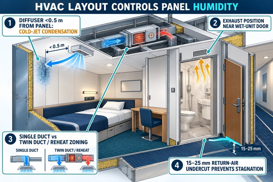
HVAC duct layout controls localized panel humidity through four design parameters: supply diffuser throw angles (causing cold-jet condensation when hitting panels within 0.5 meters), exhaust grille distance from wet-unit doors, single-duct versus twin-duct reheat zoning (ISO 7547), and return-air undercuts (15 to 25 mm) preventing stagnant room pockets.
Supply Diffuser Throw Angles and Wet-Unit Exhaust Grille Positioning
Many interior contractors blame the panel manufacturer when moisture appears on cabin walls. However, in more than half of the cases I investigate, the real culprit is the HVAC duct layout. Four layout parameters directly control localized humidity around marine accommodation panels. First, supply diffuser throw angles determine whether cold supply air hits the panels directly. Marine air conditioning units supply chilled air at 13°C to 16°C18 into the cabin through ceiling diffusers. If installers mount a ceiling diffuser within 0.5 meters of a B-15 wall panel, or if they use a diffuser without horizontal Coanda-effect louvers, the 14°C air jet blows directly against the wall panel. This cold jet chills a 0.5 m² patch of the steel wall panel down to 15°C. When a crew member opens the cabin door or steps out of the shower, warm 25°C cabin air hits that 15°C panel patch and forms immediate liquid condensation. Second, the distance between the exhaust grille and the wet-unit door controls steam spillover. A prefabricated marine wet unit has an internal exhaust vent pulling 50 to 80 m³/h of air19. However, when a crew member opens the wet-unit fire door after a hot shower, a cloud of 90% relative humidity steam escapes into the cabin entryway. If the cabin return path or auxiliary exhaust grille sits more than 1.5 meters away from the bathroom door, that steam condenses on the entryway wall panels and door frames before the HVAC system can capture it.
Single-Duct Versus Twin-Duct Reheat Zoning and Return-Air Door Undercuts
The third parameter is single-duct versus twin-duct or terminal reheat zoning under ISO 7547. Low-budget cargo vessels often use a central single-duct system without individual cabin reheaters. During mild or rainy weather, the cooling load drops, so the central system reduces airflow or raises supply temperature without dehumidifying the air properly. As a result, cabin relative humidity climbs to 65% or 75%. In contrast, offshore vessels and passenger ships use twin-duct systems or single-duct systems with electric terminal reheaters. These layouts sub-cool the supply air to 12°C at the central unit to wring out moisture, and then reheat the air at each cabin box to 18°C or 20°C. This process locks cabin humidity strictly between 45% and 55%. The fourth parameter is the return-air door undercut or ventilation louver. To keep a continuous airflow loop moving across the cabin panels, air supplied from the ceiling must exit into the corridor return duct. Under SOLAS Chapter II-2, B-15 cabin doors can use either a certified intumescent fire louver in the lower half of the door leaf or a 15 mm to 25 mm bottom door undercut. According to ISO 7547, this opening must keep the transfer air velocity under 2.0 to 2.5 m/s to prevent wind noise while ensuring 100% of the cabin air sweeps smoothly from the ceiling down across the wall panels. When contractors forget the door undercut or install a tight threshold seal on a non-watertight cabin door, cabin air pressure builds up, supply airflow drops by 40%, and moisture collects across every wall panel in the room.
| HVAC Duct Layout Parameter | Poor Layout Specification | Resulting Panel Humidity | Correct Layout Specification (ISO 7547) | Resulting Panel Humidity |
|---|---|---|---|---|
| Supply Diffuser Distance | Under 0.5 m from wall panel | 85% to 100% RH (Cold spot sweat) | Minimum 0.8 m to 1.2 m with horizontal throw | 45% to 55% RH (Dry skin) |
| Wet-Unit Exhaust Capture | Over 1.5 m from bathroom door | 75% to 90% RH on corridor panels | Inside wet unit + 50 Pa negative pressure | 50% to 60% RH at door |
| System Reheat Zoning | Single-duct without reheat | 65% to 75% RH in rainy weather | Sub-cool to 12°C + terminal cabin reheat | 45% to 50% RH year-round |
| Return-Air Door Path | 0 to 5 mm gap (blocked return) | 70% to 85% RH (stagnant cabin) | 15 to 25 mm undercut or B-15 intumescent louver | 45% to 55% RH (full sweep) |
Conclusion
Ventilated ship cabins keep panel humidity between 40% and 60%, while enclosed voids trap up to 98% humidity. Pairing hydrophobic rockwool panels with proper airflow prevents costly moisture damage.
-
"Sea surface temperature", https://charts.ecmwf.int/products/medium-sst. Climatological sea-surface temperature datasets from NOAA, Copernicus, or national oceanographic agencies can substantiate that North Atlantic and North Sea waters commonly fall within low single-digit to roughly 10 °C seasonal ranges, providing environmental context for cold hull boundary conditions. Evidence role: statistic; source type: government. Supports: Seawater along North Atlantic or North Sea routes often ranges from 2°C to 10°C.. Scope note: Sea temperature varies by season, depth, latitude, and route; such data support the plausibility of the range rather than a constant operating condition for all voyages. ↩
-
"Thermal Conductivity", http://hyperphysics.phy-astr.gsu.edu/hbase/Tables/thrcn.html. Engineering reference data for carbon or mild steel report thermal conductivity values on the order of 45–60 W/m·K near room temperature, supporting the use of approximately 50 W/m·K as a representative value in heat-transfer discussion. Evidence role: definition; source type: education. Supports: Steel has a thermal conductivity of about 50 W/m·K.. Scope note: The exact conductivity depends on steel alloy, temperature, and composition, so the cited value should be treated as representative rather than universal. ↩
-
"Vapor Barriers - Building Science Education", https://bsesc.energy.gov/energy-basics/vapor-barriers. ASTM E96 defines methods for measuring water-vapor transmission, while building-science classifications commonly identify materials at or below 0.1 perm as very low-permeance vapor barriers; together these sources support classifying a steel/PVC-faced panel as highly vapor resistant if tested below that value. Evidence role: definition; source type: institution. Supports: A steel and PVC panel assembly with measured permeance below 0.1 perm is a very low-permeance vapor barrier under ASTM E96-style testing and common vapor-retarder classifications.. Scope note: ASTM E96 provides a test method, not a universal published permeance value for every steel/PVC marine panel; the specific assembly value would require product testing or manufacturer data. ↩
-
"Evaporation, Heat Transfer, and Velocity Distribution in ...", https://ntrs.nasa.gov/citations/20030068788. A heat- and mass-transfer source explains that air movement reduces the thickness of the near-surface boundary layer, increasing convective moisture transfer and evaporation from wet or humid surfaces. Evidence role: mechanism; source type: paper. Supports: Airflow disrupts the stagnant boundary layer on a panel surface and promotes moisture removal.. Scope note: This supports the physical mechanism generally; it does not verify the article’s specific evaporation-rate figures for ship wall panels. ↩
-
"Dew Point and Relative Humidity Calculations", https://www.wpc.ncep.noaa.gov/html/dewrh.shtml. A psychrometric reference or calculator supports that indoor air at 22°C and 50% relative humidity has a dew point of approximately 11°C, and that condensation occurs when a surface is at or below the dew-point temperature. Evidence role: mechanism; source type: education. Supports: Air at 22°C and 50% relative humidity has a dew point near 11.1°C, so a panel surface near 20°C to 21°C should not form dew under those conditions.. Scope note: This supports the thermodynamic calculation under equilibrium conditions; local thermal bridges, cold exterior structure, or transient humidity spikes can alter actual condensation risk. ↩
-
"Water Vapor Generation in Residential Buildings", https://research.fs.usda.gov/download/treesearch/65595.pdf. Indoor-air-quality and HVAC references report that occupants emit water vapor through respiration and perspiration, with moisture-generation rates depending on activity level, clothing, and ambient conditions. Evidence role: statistic; source type: institution. Supports: Two sleeping crew members can add roughly 80–120 grams of water vapor per hour to a cabin through breathing and perspiration.. Scope note: Published values are usually given as ranges by activity and environment; they may support the order of magnitude rather than this exact two-person cabin scenario. ↩
-
"How to choose the right marine wall panels for marine interior ...", https://magellanmarinetech.com/how-choose-right-marine-wall-panels-for-marine-interior-projects/. Ship accommodation or classification-society guidance can document typical service cavities behind marine lining systems and their use for routing cables or pipes; such evidence supports the construction context rather than proving a universal cavity dimension. Evidence role: general_support; source type: institution. Supports: Marine lining panels are commonly installed with an enclosed service void of roughly 50 mm to 150 mm between hull insulation and the panel back for cables and pipes.. Scope note: Cavity depth may vary by shipyard, panel system, fire rating, and outfitting design. ↩
-
"How Does Condensation Risk Differ for Marine ...", https://magellanmarinetech.com/how-condensation-risk-differ-for-marine-accommodation-panels-by-route/. A shipboard hygrothermal monitoring study or marine HVAC technical report can support the occurrence of very high relative humidity in poorly ventilated hull-to-lining cavities; the source should be treated as contextual if it reports comparable compartments rather than the exact panel cavity described here. Evidence role: statistic; source type: research. Supports: Hull-to-lining voids can regularly experience relative humidity in the range of 85% to 98%.. Scope note: Measured relative humidity will depend on vessel type, climate route, ventilation leakage, insulation design, and operating conditions. ↩
-
"How Does Thermal Conductivity Affect Marine ...", https://magellanmarinetech.com/how-thermal-conductivity-affect-marine-accommodation-panel-u-values/. ISO 7547 establishes design conditions for ship air-conditioning and ventilation calculations, including cold-weather outside air and indoor accommodation assumptions; this supports the cited design basis, although access to the standard may be needed to verify the exact temperature values. Evidence role: definition; source type: institution. Supports: ISO 7547 is an applicable basis for ship HVAC winter design assumptions such as low outdoor temperature and heated indoor accommodation conditions.. Scope note: The standard supports design assumptions, not measured temperatures inside a specific unheated lining void. ↩
-
"Model and Experiments for Hygrothermal Conditions of the ...", https://web.ornl.gov/sci/buildings/conf-archive/2001%20B8%20papers/054_Rode.pdf. A hygrothermal calculation standard, laboratory study, or shipboard condensation survey can substantiate plausible daily condensation fluxes on cold metal surfaces exposed to humid air; if the source is a model, it supports the mechanism and magnitude under stated boundary conditions rather than a universal shipboard rate. Evidence role: statistic; source type: paper. Supports: Moist air contacting cold hull stiffeners or cooled panel backs can produce daily condensation in the approximate range of 150 to 400 g/m².. Scope note: Condensation rate is highly sensitive to surface temperature, air leakage, ventilation, humidity, and duration of exposure. ↩
-
"Insulation", https://energy.gov/sites/prod/files/2013/11/f5/insulation_guide.pdf. Building-science and HVAC references explain that condensation forms on a surface when its temperature is below the dew-point temperature of the surrounding air, supporting the mechanism by which uninsulated chilled-water piping can produce liquid water in a humid plenum. Evidence role: mechanism; source type: education. Supports: Exposed chilled-water pipe sections can condense water rapidly when humid plenum air contacts pipe surfaces below dew point.. Scope note: Such sources establish the physical mechanism but do not quantify the drip rate for this specific ceiling-plenum configuration. ↩
-
"A Field Study of Indoor Moisture Problems and Damage in New ...", https://web.ornl.gov/sci/buildings/conf-archive/1992%20B5%20papers/073.pdf. Indoor-air-quality and ventilation studies show that bathing and showering can raise bathroom relative humidity to high levels, often near saturation, supporting the assertion that bathroom exhaust streams may carry very humid air. Evidence role: general_support; source type: paper. Supports: Bathroom exhaust ducts can carry air with relative humidity in the 80% to 95% range after wet-room use.. Scope note: The evidence is likely to describe bathrooms generally and may not directly measure humidity in marine wet-unit exhaust ducts. ↩
-
"Effect of recirculation zones on the ventilation of a public ...", https://pmc.ncbi.nlm.nih.gov/articles/PMC8597714/. Fluid-dynamics and room-ventilation studies describe separation and recirculation in flows around sharp corners and recesses, supporting the general mechanism by which these geometries can create low-velocity zones. Evidence role: mechanism; source type: paper. Supports: Sharp 90-degree corners and pillar recesses can cause airflow separation and eddy-like low-velocity zones.. Scope note: Such sources would support the airflow mechanism, but may not verify the article’s specific cabin geometry or ASHRAE Standard 26 reference. ↩
-
"Field Experiments to Identify and Eliminate Recirculation ...", https://pmc.ncbi.nlm.nih.gov/articles/PMC9098795/. Experimental or CFD studies of indoor air distribution can document that near-corner and recessed zones often have much lower velocities than the occupied-zone mean, giving contextual support for very low local air speeds. Evidence role: statistic; source type: paper. Supports: Air velocity in a narrow corner zone can fall to very low levels compared with the room-center velocity.. Scope note: A general ventilation study would not by itself prove the exact threshold of 0.02 m/s in marine cabins without matching measurements or simulations. ↩
-
"Moisture control and ventilation - NCBI - NIH", https://www.ncbi.nlm.nih.gov/books/NBK143947/. Building-physics literature on ventilation and moisture buffering shows that poorly ventilated or stagnant micro-zones dry more slowly and can reach higher local relative humidity than the room average after moisture release. Evidence role: mechanism; source type: research. Supports: Moisture can persist in stagnant cabin corners and elevate local relative humidity above the room-average value.. Scope note: Such evidence would support the moisture-accumulation mechanism but may not validate the exact 70–80% RH range for the described vessel cabins. ↩
-
"Water Vapor Generation in Residential Buildings", https://research.fs.usda.gov/download/treesearch/65595.pdf. Indoor-air and thermal-comfort references report that resting or sleeping occupants emit water vapor through respiration and perspiration, supporting the claim that a bunk occupant contributes moisture to the surrounding microclimate. Evidence role: mechanism; source type: institution. Supports: Sleeping occupants release water vapor that can add moisture near a bunk or mattress.. Scope note: Occupant moisture-generation rates vary with activity level, temperature, clothing, and ventilation, so the source would not specify the exact amount entering the furniture gap. ↩
-
"Thermal Insulation of Protective Clothing Materials in Extreme ...", https://pmc.ncbi.nlm.nih.gov/articles/PMC10024235/. Thermal-property tables for wood, textiles, foam, and bedding materials can support the general assertion that wardrobes, stored clothing, and mattresses add appreciable thermal resistance between room air and a wall surface. Evidence role: statistic; source type: education. Supports: Furniture and bedding can provide enough thermal resistance to shield the wall panel from room heat.. Scope note: The stated R-value range depends strongly on material composition, thickness, compression, and air gaps, so a generic table would provide contextual rather than direct verification. ↩
-
"HVAC Design Manual", https://www.cfm.va.gov/til/dmanual/dmHVAC.pdf. A marine HVAC design reference or ISO 7547-related source should document typical supply-air temperature ranges for ship accommodation air-conditioning systems; this would support the stated range as an industry design condition rather than a universal requirement. Evidence role: general_support; source type: institution. Supports: Marine accommodation air-conditioning systems commonly deliver chilled supply air in the range of about 13°C to 16°C.. Scope note: The exact 13°C to 16°C range may vary by vessel type, climate notation, and system design. ↩
-
"requirements for ventilation of different rooms on the ships", https://www.academia.edu/97496025/Main_requirements_for_ventilation_of_different_rooms_on_the_ships. A ship accommodation ventilation standard or classification-society guidance should give typical exhaust airflow requirements for sanitary spaces or wet units, supporting the stated 50–80 m³/h range as a design benchmark. Evidence role: statistic; source type: institution. Supports: Prefabricated marine wet units commonly require mechanical exhaust airflow on the order of 50 to 80 m³/h.. Scope note: Required exhaust rates may differ by flag state, classification society, cabin occupancy, and bathroom size. ↩