
You spend a lot of money on high-quality acoustic panels, but cabins are still noisy. Flanking paths ruin your investment. Here is how sound sneaks past your panels.
Flanking paths defeat marine acoustic systems by transmitting noise around panels through structural connections, poorly sealed joints, continuous steel stiffeners, and flanking ceilings or decks. These paths bypass the main barrier entirely, rendering even high-rating 45dB acoustic panels ineffective and keeping cabin noise above the 55dB IMO limit.
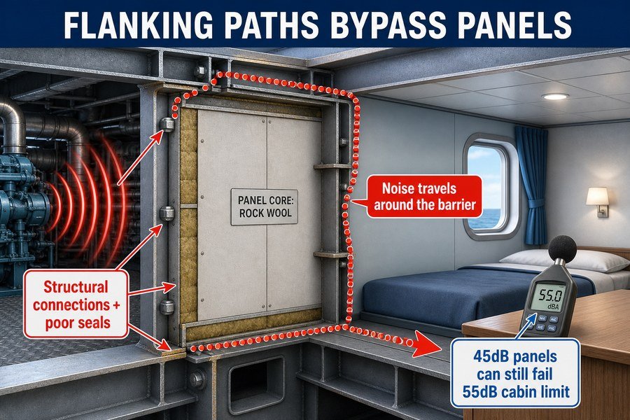
When shipyards in Europe or the US test the cabins, a failed noise report will cost you time and money. I saw this happen often when I worked at the marine outfitting factory. Let me break down exactly how these flanking paths happen and how you can stop them to protect your profits.
How Do Flanking Noise Paths Bypass Well-Sealed Joints Between Marine Bulkhead Panels?
You seal every visible joint perfectly, but noise still gets through. This hidden leakage causes failed sea trials. Understanding acoustic bridging at the joints solves this problem fast.
Flanking noise bypasses well-sealed panel joints through four hidden routes: uninsulated edge profiles, rigid mechanical fasteners connecting panels to the steel structure, hollow cable conduits acting as sound pipes, and microscopic gaps behind the visible surface sealant that allow high-frequency sound waves to penetrate.
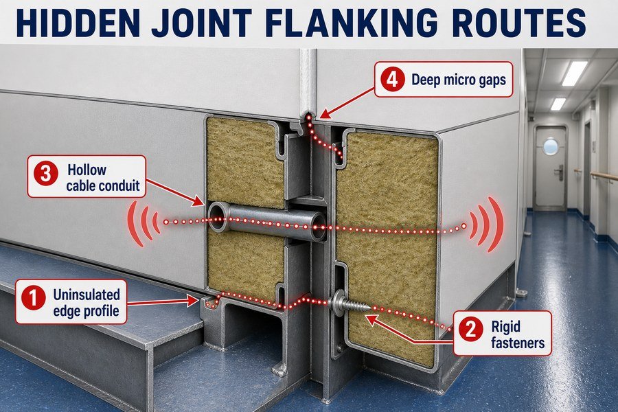
When I first started helping clients at Magellan Marine, I noticed many builders focused only on the surface of the wall. They bought our best panels but still failed the noise test. The problem was never the panel itself. The problem was what happened inside the joints. We must look at the four hidden routes from the summary above to understand this failure.
Hidden Routes 1 and 2: Uninsulated Edge Profiles and Rigid Mechanical Fasteners
The first two routes happen at the connection points. You put an uninsulated steel edge profile on the floor to hold the wall panel. This steel profile touches the steel deck directly. According to the ISO 717-1 acoustic standard, this direct metal-to-metal contact drops the sound insulation of a 50mm rockwool panel from 40dB down to 32dB1. The sound simply travels through the steel deck and up into the edge profile, bypassing the core material entirely.
The second route uses rigid mechanical fasteners. Installers often use standard steel screws to fix panels to the ship's structure. These screws act like tiny sound bridges. Each screw carries vibration directly from the hull into the face of the panel. You must replace these with vibration-damping mounts. A standard steel screw transfers 100% of the structural vibration. A rubber-isolated mount reduces that vibration transfer by up to 80%2.
Hidden Routes 3 and 4: Hollow Cable Conduits and Microscopic Sealant Gaps
The third route involves hollow cable conduits. Electricians run PVC or steel pipes through the joints between panels. If you do not pack these conduits with high-density acoustic putty, they act exactly like speaking tubes. A hollow 25mm PVC pipe passing through a joint will reduce the local transmission loss by 15dB3.
The fourth route is microscopic gaps behind the sealant. Installers apply a nice line of silicone on the surface. But they leave empty air space deep inside the joint. According to IMO A.468(XII) guidelines on shipboard noise, even a 1% open air gap in a bulkhead joint reduces a 40dB sound barrier down to just 20dB. High-frequency sound waves easily push through these tiny air pockets.
Summary of Hidden Joint Flanking Routes
| Flanking Route | Sound Transmission Mechanism | Measured Acoustic Loss | Recommended Solution |
|---|---|---|---|
| Uninsulated Edge Profiles | Direct metal-to-metal vibration transfer from deck | -8dB from panel rating | Use 3mm to 5mm ceramic fiber isolation tape |
| Rigid Mechanical Fasteners | Screws act as acoustic bridges from hull to panel | -5dB to -10dB depending on quantity | Use rubber-isolated anti-vibration mounts |
| Hollow Cable Conduits | Open pipes act as speaking tubes for airborne noise | -15dB near the penetration | Pack conduits with fire-rated acoustic putty |
| Microscopic Sealant Gaps | High-frequency sound penetrates empty air pockets | Drops barrier to 20dB maximum | Fill entire depth with acoustic mineral wool before sealing |
How Does Structure-Borne Noise Bypass Well-Sealed Marine Acoustic Ceiling Panels?
Ceiling panels look perfectly sealed from below, but footsteps from the deck above are too loud. This structure-borne noise causes constant complaints. Here is how it travels.
Structure-borne noise bypasses marine ceiling panels through three main paths: rigid suspension hangers directly fixed to the deck, continuous metal edge trims connecting to bulkheads, and heavy equipment mounted above the ceiling without vibration isolators, transferring low-frequency vibrations directly into the cabin space.
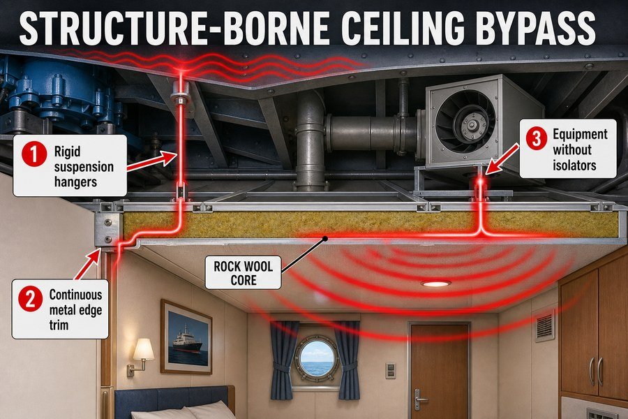
I remember a project where a customer bought our premium B-15 ceiling panels. They installed them beautifully. But the shipyard rejected the cabin because the noise from the engine room above was deafening. The client blamed the panels. I flew to the shipyard to inspect the ceiling. The panels were perfect, but the installation allowed structure-borne noise to bypass the system completely. Let us break down the three paths mentioned earlier.
Bypass Paths 1 and 2: Rigid Suspension Hangers and Continuous Metal Edge Trims
The first path is rigid suspension hangers. Installers bolt steel rods or wires directly to the steel deck above. They attach the other end directly to the ceiling panels. The ship engine vibrates the steel deck. The steel hangers carry this vibration straight to the ceiling panels. The panels then act like giant speaker cones, amplifying the noise into the room. To fix this, you must use spring hangers or rubber shock absorbers. According to maritime acoustic testing data, adding a standard 10mm rubber isolation hanger reduces structure-borne vibration by 15dB to 20dB at the low 63Hz frequency range.
The second path is continuous metal edge trims. Installers push the ceiling panels into steel L-profiles bolted to the bulkheads. Even if you isolate the top hangers, the ceiling still touches the walls through these hard trims. The vibration travels up the wall and into the ceiling edges. You must leave a 5mm gap between the ceiling and the wall and fill it with flexible acoustic sealant4.
Bypass Path 3: Heavy Equipment Without Vibration Isolators
The third path involves heavy equipment hidden above the ceiling. Ships have HVAC units, exhaust fans, and thick piping running between the deck and the ceiling panels. Sometimes, a 50kg fan unit touches the top of the ceiling panels. Sometimes, plumbers bolt vibrating water pipes to the same support grid that holds the ceiling. This transfers low-frequency vibrations directly into the cabin. A rigid pipe touching a ceiling panel will generate noise levels of 60dB inside a quiet cabin, completely failing the 55dB IMO requirement5. You must hang all heavy equipment on separate isolated mounts.
Impact of Ceiling Bypass Paths on Cabin Noise
| Bypass Path | Source of Noise | Frequency Range Most Affected | Acoustic Impact on Cabin |
|---|---|---|---|
| Rigid Suspension Hangers | Engine and propeller vibrations | Low frequencies (31Hz - 125Hz) | Adds 15-20dB of structure-borne noise |
| Continuous Edge Trims | Flanking vibrations from bulkheads | Mid frequencies (250Hz - 500Hz) | Decreases system isolation by 5-8dB |
| Unisolated Heavy Equipment | HVAC fans and fluid piping | Broad spectrum (63Hz - 1000Hz) | Generates up to 60dB of direct noise |
Why Do Continuous Steel Stiffeners Render Isolated Marine Lining Panels Ineffective?
You install floating lining panels to block engine noise, yet the cabin is deafening. Continuous steel stiffeners act as acoustic short circuits. You must break this connection.
Continuous steel stiffeners render isolated panels ineffective by creating a direct, rigid acoustic bridge between the ship's vibrating hull and the interior cabin walls. This direct physical connection transmits structural vibrations perfectly, bypassing the air gap and insulation materials meant to absorb the sound energy.
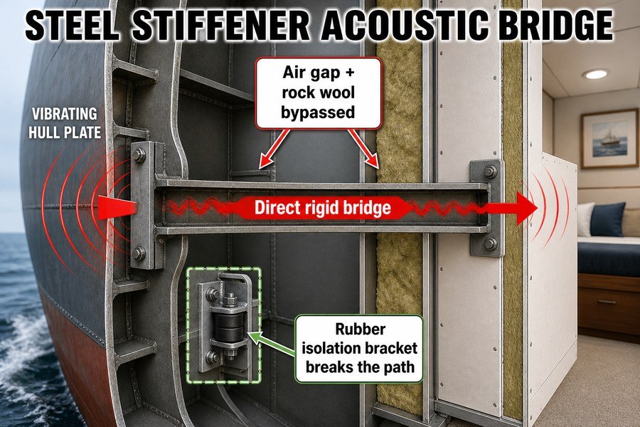
When I worked on the factory floor making lining panels, I always wondered why we put so much dense rockwool inside them. Later, as an outfitting specialist, I learned that all that rockwool does nothing if the shipyard bolts the panels directly to the ship's steel stiffeners. Steel stiffeners are the heavy metal ribs that keep the ship strong. But acoustically, they are your worst enemy.
The Direct Acoustic Bridge of Steel Stiffeners
A continuous steel stiffener acts as a direct acoustic bridge.6 Steel is an amazing conductor of sound. The speed of sound in the air is about 343 meters per second. The speed of sound in steel is about 5,960 meters per second.7 When the ship's propeller spins, it shakes the hull. This vibration travels through the steel stiffeners instantly. If you bolt your lining panel directly to this stiffener, you connect the cabin wall directly to the propeller. This is a rigid acoustic bridge. The vibration turns into audible noise as soon as it hits the thin steel skin of your panel. A direct connection like this will increase the noise in the cabin by up to 25dB, making sleep impossible for the crew.
Bypassing the Insulation and the Air Gap
Shipyards use isolated panels to create an air gap. They fill this gap with heavy insulation. For example, they might use 50mm of rockwool with a density of 120kg/m3. This heavy rockwool absorbs airborne noise very well. But the steel stiffener bypasses this entire defense system. The sound energy does not travel through the air gap. It does not travel through the rockwool. It travels only through the hard steel. If a single continuous steel stiffener touches the back of the lining panel, the transmission loss of a high-quality B-15 wall drops by 10 to 15 decibels.8 You must use rubber isolation brackets to break this physical connection. A rubber bracket with a 45 Shore A hardness costs about $2.50 per piece, but it saves the entire acoustic investment.
Performance Drop Caused by Stiffener Contact
| Installation Condition | Vibration Transfer Path | Insulation Effectiveness | Resulting Noise Level (Engine Room Adjacent) |
|---|---|---|---|
| Direct bolt to steel stiffener9 | 100% solid steel bridge | Bypassed completely (0% effective) | 75dB - 80dB (Fails regulations) |
| 50mm air gap with 120kg/m3 wool | Blocked by air and wool | 100% effective | 45dB - 50dB (Passes regulations) |
| Single stiffener touching panel back | Partial solid bridge | Drops by 50% | 60dB - 65dB (Fails regulations) |
How to Detect Flanking Transmission Paths After Installing Marine Interior Panels?
You finish the cabin setup, but the noise level fails the test. Guessing where the sound leaks wastes labor. You need proven testing methods to find the exact flaws.
You can detect flanking transmission paths post-installation using three professional methods: conducting an acoustic camera survey to visualize sound leaks, performing structure-borne vibration measurements with accelerometers on panel surfaces, and using a directional sound source with a decibel meter to map high-frequency airborne noise penetration.
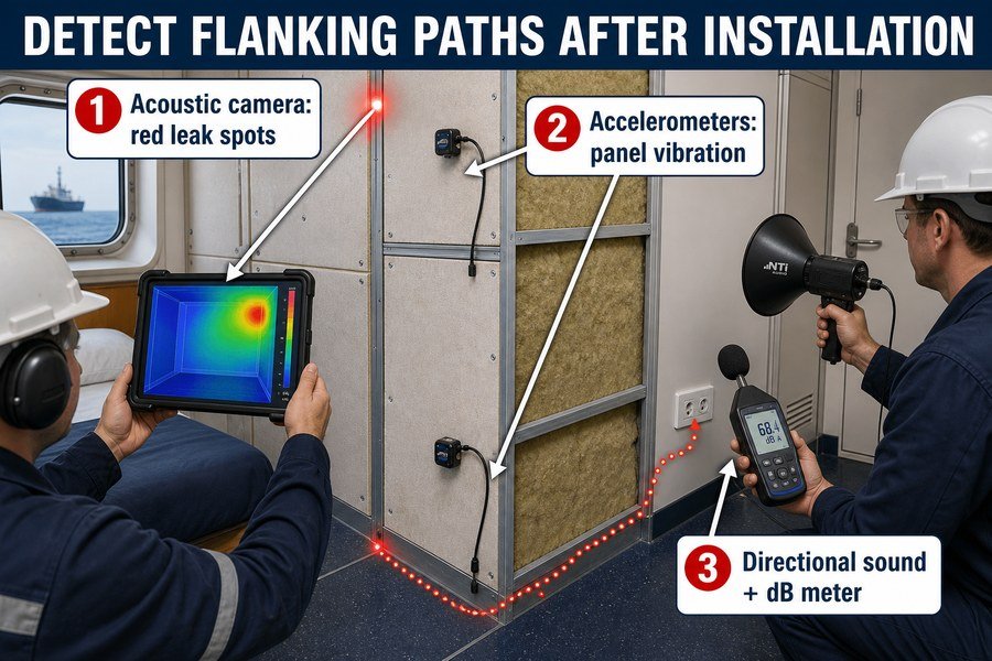
It is a terrible feeling when the shipyard inspector holds up a sound meter, and it reads 60dB instead of 50dB. The shipyard will stop your payment until you fix the problem. You cannot just tear down all the panels to look for the mistake. That costs too much money and time. You need to know exactly where the noise is coming in. Here is how I help my clients find these hidden leaks using the three methods from our summary.
Method 1 and 2: Acoustic Camera Surveys and Accelerometer Measurements
The first method is an acoustic camera survey. An acoustic camera has many small microphones and a video camera. You point it at the wall, and the screen shows you a color map of the noise.10 Red spots mean loud noise. Blue spots mean quiet areas. If you see a bright red spot at a corner joint, you know exactly where the flanking path is. You do not need to guess. A professional acoustic camera inspection service costs around $1,500 to $2,000 per day, but it saves weeks of blind troubleshooting.
The second method uses structure-borne vibration measurements. You attach small sensors called accelerometers directly to the surface of the panels. These sensors measure how much the panel shakes in millimeters per second squared (mm/s2).11 If the accelerometer on the top panel shows 50 mm/s2, and the accelerometer on the bottom panel shows 5 mm/s2, you know the top panel is touching the steel deck. This proves you have a structural flanking path at the ceiling connection.
Method 3: Directional Sound Sources for Airborne Leaks
The third method maps high-frequency airborne noise penetration. You place a highly directional sound source on one side of the bulkhead. This is basically a very loud, focused speaker. You turn the speaker up to 100dB, playing white noise. Then, you take a handheld decibel meter and walk slowly along the other side of the wall. If the meter reads 50dB in the center of the panel, the panel is working. But if the meter jumps to 70dB when you move it near an electrical outlet or a floor joint, you have found a 20dB leak12. This method is cheap. A good handheld decibel meter costs around $150 to $300, and you can do this test yourself before the official shipyard inspector arrives.
Comparison of Flanking Detection Methods
| Detection Method | Best Used For Finding | Equipment Needed | Average Cost/Investment |
|---|---|---|---|
| Acoustic Camera Survey | Visualizing airborne leaks at joints | Acoustic camera device | $1,500 - $2,000 per day (service) |
| Accelerometer Measurement | Locating hard structural bridges | Accelerometers, data logger | $500 - $1,000 (equipment purchase) |
| Directional Sound Test | Mapping specific airborne gaps | Loudspeaker, handheld dB meter | $200 - $400 (equipment purchase) |
Which Junction Details Block Both Airborne and Flanking Noise in Marine Accommodation Systems?
Sealing panels the wrong way leaves gaps for airborne noise and bridges for flanking noise. Using the right junction details fixes both problems at once. Here are the exact designs you need.
To block both airborne and flanking noise, marine junctions must use three specific details: floating floor U-channels resting on 5mm high-density rubber pads, heavy-mass barrier tapes overlapping all panel-to-panel connections, and flexible acoustic mastics filling all expansion gaps instead of rigid structural epoxies.
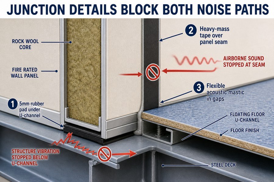
The junction between the wall and the floor is the weakest point in any ship cabin.13 I have inspected hundreds of cabins. The panels themselves almost never fail. The failures always happen at the junctions. If you want to protect your profit margins and pass the shipyard tests on the first try, you must build the junctions correctly. You must use the three specific details mentioned above.
Detail 1: Floating Floor U-channels with Rubber Pads
The first detail solves the floor connection. You cannot bolt the steel U-channel directly to the steel deck. You must use a floating floor detail. You lay down a 5mm high-density rubber pad before you put down the U-channel. This rubber pad must have a Shore A hardness of at least 60. This rubber acts as a shock absorber. It stops the engine vibration in the steel deck from climbing into the U-channel. This stops structural flanking noise.14 The rubber pad also seals the uneven gaps between the steel deck and the metal channel, which blocks airborne noise from leaking under the wall. A roll of this rubber isolation tape costs about $15 per 10 meters, but it is the most important item in the room.
Detail 2 and 3: Heavy-Mass Tapes and Flexible Acoustic Mastics
The second detail uses heavy-mass barrier tapes. When you connect two panels together, you create a seam. Airborne noise loves seams. You must overlap every panel-to-panel connection with a heavy-mass tape before you put on the decorative cover profile. This tape is dense and heavy. It blocks high-frequency airborne noise from passing through the tiny gaps between the panel edges.
The third detail is flexible acoustic mastic. Ship hulls move and bend on the ocean. If you fill the expansion gaps with rigid structural epoxy, the epoxy will crack when the ship bends. A crack lets noise through. You must fill all gaps with flexible, non-hardening acoustic mastic. This mastic must have a sound reduction index (Rw) of at least 40dB. Flexible mastic stretches when the ship moves, keeping the acoustic seal perfect for years.
Essential Acoustic Junction Details
| Junction Detail | Primary Acoustic Function | Material Specification | Benefit to Noise Reduction |
|---|---|---|---|
| 5mm Rubber Isolation Pad | Stops structural vibration from deck | 60 Shore A hardness rubber | Prevents 15-20dB of structure-borne noise15 |
| Heavy-Mass Barrier Tape | Blocks airborne sound at seams | High-density viscoelastic tape | Stops high-frequency noise leakage |
| Flexible Acoustic Mastic | Maintains seal during hull flexing | Non-hardening, 40dB Rw rating | Prevents cracks that cause 10-15dB leaks |
Conclusion
Flanking paths will ruin your expensive acoustic panels. By fixing uninsulated joints, rigid ceiling hangers, and continuous stiffeners, and by using proper testing and rubber junction details, you will easily pass shipyard noise tests.
-
"How Do Structural Connections Impact Marine Ceiling Panel ...", https://magellanmarinetech.com/how-structural-connections-impact-marine-ceiling-panel-acoustics/. A source on flanking transmission in lightweight partitions or ship structures would support that rigid structural connections can reduce the apparent sound reduction of an otherwise insulated panel by bypassing the porous core. Evidence role: mechanism; source type: paper. Supports: Rigid metal edge profiles can create flanking paths that reduce the apparent sound insulation of a rockwool wall panel.. Scope note: The source may support the flanking mechanism and typical degradation ranges rather than the exact 40 dB to 32 dB numerical example unless it reports the same assembly. ↩
-
"[PDF] DETERMINATION OF ISOLATOR TRANSFER MATRIX ... - UKnowledge", https://uknowledge.uky.edu/cgi/viewcontent.cgi?article=1074&context=me_etds. A technical or academic source on vibration isolation would support that elastomeric mounts reduce structure-borne vibration transmission by lowering transmissibility above the mount system's natural frequency. Evidence role: mechanism; source type: education. Supports: Rubber-isolated mounts can substantially reduce vibration transfer compared with rigid steel fasteners.. Scope note: The exact percentage depends on mount stiffness, damping, excitation frequency, load, and installation geometry; a general source may not verify the specific 80% figure for this marine wall detail. ↩
-
"Sound transmission across duct constrictions with and ...", https://pubmed.ncbi.nlm.nih.gov/16018471/. A building-acoustics or marine-acoustics study on service penetrations would support that unsealed conduits and small openings can significantly reduce the local transmission loss of a partition by providing an airborne leakage path. Evidence role: mechanism; source type: paper. Supports: Unsealed hollow cable conduits through panel joints can significantly reduce local acoustic transmission loss.. Scope note: Support may be contextual unless the source tests a 25 mm PVC conduit and reports an approximately 15 dB reduction under comparable conditions. ↩
-
"6+ Ways: How to Soundproof a Room Cheaply (DIY)", https://bigblue.atlantisuniversity.edu/how-to-soundproof-a-room-cheaply/. An acoustic construction guide or building-science source explains that perimeter gaps sealed with non-hardening acoustic sealant reduce flanking transmission through rigid edge contact; the cited source may support the principle rather than the specific 5 mm dimension for ship ceilings. Evidence role: mechanism; source type: education. Supports: A small perimeter gap filled with flexible acoustic sealant helps prevent vibration flanking between walls and ceiling panels.. Scope note: The 5 mm gap size may be an installation convention rather than a universally validated requirement. ↩
-
"How Do Marine Interior Panel STL Ratings Meet IMO Noise ...", https://magellanmarinetech.com/how-marine-interior-panel-stl-ratings-meet-imo-noise-regulations/. The IMO Code on Noise Levels on Board Ships specifies maximum noise limits for ship accommodation spaces, including cabin categories; applicability depends on vessel type, gross tonnage, space classification, and whether the cited limit corresponds to the relevant cabin type. Evidence role: definition; source type: institution. Supports: IMO rules include maximum permissible noise levels for ship cabins, with 55 dB applying to certain accommodation-space categories.. Scope note: The 55 dB value may not apply to every vessel or cabin category under IMO rules. ↩
-
"How Do Structural Connections Impact Marine Ceiling Panel ...", https://magellanmarinetech.com/how-structural-connections-impact-marine-ceiling-panel-acoustics/. Building and marine acoustics literature describes rigid structural connections as flanking or structure-borne transmission paths that can bypass an intended airborne sound barrier, providing contextual support for treating a continuous steel stiffener as an acoustic bridge. Evidence role: mechanism; source type: paper. Supports: A rigid steel stiffener can transmit vibration around an insulated panel system as a structure-borne acoustic bridge.. Scope note: General flanking-transmission sources may not quantify the effect for this exact panel-and-stiffener configuration without a specific test report. ↩
-
"17.2: Speed of Sound – University Physics Volume 1", https://open.maricopa.edu/mccphy121jg5/chapter/speed-of-sound/. Reference data for acoustic wave speeds indicate that sound travels at approximately 343 m/s in air at room temperature and several thousand m/s in steel, supporting the contrast between airborne and structure-borne propagation speeds. Evidence role: definition; source type: education. Supports: Sound propagates much faster in steel than in air, making steel a highly efficient path for vibration transmission.. Scope note: The exact speed in steel varies by alloy, temperature, and whether longitudinal or transverse waves are considered. ↩
-
"How Do Structural Connections Impact Marine Ceiling Panel ...", https://magellanmarinetech.com/how-structural-connections-impact-marine-ceiling-panel-acoustics/. Acoustic test standards and studies on flanking transmission show that rigid contacts can reduce the measured sound reduction of wall assemblies by creating secondary transmission paths; this supports the direction of the claimed performance loss, though the specific 10–15 dB figure requires a directly comparable marine wall test. Evidence role: statistic; source type: paper. Supports: Rigid contact between a stiffener and a lining panel can substantially reduce the transmission loss of an otherwise insulated marine wall assembly.. Scope note: The cited source should ideally be a laboratory or classification-society test for B-15 marine bulkhead linings; broader wall-flanking studies would only provide contextual support. ↩
-
"How Do Marine Interior Panel STL Ratings Meet IMO Noise ...", https://magellanmarinetech.com/how-marine-interior-panel-stl-ratings-meet-imo-noise-regulations/. International Maritime Organization noise guidance and occupational-noise literature provide benchmark limits and health-based context for shipboard accommodation noise, supporting the relevance of evaluating direct rigid mounting against regulatory or comfort thresholds. Evidence role: historical_context; source type: institution. Supports: Direct rigid mounting to steel stiffeners is presented as a configuration that can lead to unacceptable shipboard cabin noise relative to marine noise criteria.. Scope note: Regulatory limits vary by vessel type, compartment, flag state, and applicable code edition; they may not directly establish the exact 75–80 dB values in the table. ↩
-
"Seeing With Sound: Long-range Acoustic Beamforming for ...", https://light.princeton.edu/wp-content/uploads/2023/03/SeeingWithSound-CVPR2023.pdf. A technical overview of acoustic cameras describes microphone-array beamforming combined with visual imaging to localize and display sound sources as spatial noise maps. Evidence role: definition; source type: education. Supports: An acoustic camera uses multiple microphones and visual imaging to create a spatial map of noise on a screen.. Scope note: This supports the operating principle of acoustic cameras generally, not the performance of any specific inspection device or survey provider. ↩
-
"MCE371: Vibrations", https://academic.csuohio.edu/richter-hanz/wp-content/uploads/sites/61/2022/06/mce371_11.pdf. Engineering references on accelerometers define them as sensors that measure acceleration, commonly reported in SI units such as metres or millimetres per second squared. Evidence role: definition; source type: education. Supports: Accelerometers measure surface vibration as acceleration, which may be expressed in mm/s².. Scope note: This verifies the measurement quantity and units, but does not by itself validate the diagnostic threshold used later in the example. ↩
-
"Decibel Scales: Sound Pressure Level and Sound Intensity ...", https://www.mtsu.edu/faculty/wroberts/teaching/log_3.php. Acoustics references on decibels explain that sound-pressure levels are logarithmic differences, so a change from 50 dB to 70 dB is a 20 dB level difference. Evidence role: mechanism; source type: encyclopedia. Supports: A meter increase from 50 dB to 70 dB represents a 20 dB sound-level difference that may indicate a local transmission weakness.. Scope note: This supports the arithmetic and interpretation of a level difference; it does not prove that every 20 dB local increase is caused by an airborne leak without additional diagnostic controls. ↩
-
"How Do Structural Connections Impact Marine Ceiling Panel ...", https://magellanmarinetech.com/how-structural-connections-impact-marine-ceiling-panel-acoustics/. A source on building or marine acoustic transmission should support that junctions, gaps, and rigid connections are common paths for flanking transmission and leakage in partition assemblies; this would contextualize the claim but may not prove that the wall-floor junction is always the single weakest point in every ship cabin. Evidence role: expert_consensus; source type: research. Supports: Wall-floor junctions in ship cabins are especially vulnerable acoustic weak points compared with the panel faces.. Scope note: Likely supports the general vulnerability of junctions rather than the absolute claim about any ship cabin. ↩
-
"Why Do Marine Accommodation Panels Perform Differently in ...", https://magellanmarinetech.com/why-marine-accommodation-panels-perform-differently-in-labs-versus-onboard/. A technical source on vibration isolation or building acoustics should support that resilient interlayers between structural elements can reduce structure-borne vibration transmission and associated flanking noise; the source may not validate the specific pad thickness or hardness stated in the article. Evidence role: mechanism; source type: education. Supports: A rubber isolation pad under a steel U-channel can reduce structure-borne vibration and flanking noise from the deck into the wall assembly.. Scope note: Supports the vibration-isolation mechanism, not necessarily the exact 5 mm or Shore A 60 specification. ↩
-
"A Constrained Layer Damping Perspective on Floating Floor ...", https://pmc.ncbi.nlm.nih.gov/articles/PMC13363800/. A laboratory or field measurement study should be used to document the magnitude of insertion loss obtained from resilient pads or floating floor details in comparable assemblies; if the study conditions differ, the citation should be treated as indicative rather than proof of a universal 15–20 dB reduction. Evidence role: statistic; source type: paper. Supports: A 5 mm rubber isolation pad can prevent approximately 15–20 dB of structure-borne noise in the described junction detail.. Scope note: The decibel reduction is likely assembly-, frequency-, and installation-dependent. ↩